RAKK dac. RAKK dac Mark III. Extreme RAKK dac. Assembly Manual. K&K Audio. Raleigh Audio
|
|
|
- Erin Thomas
- 5 years ago
- Views:
Transcription
1 RAKK dac K&K Audio RAKK dac Mark III Raleigh Audio Extreme RAKK dac Assembly Manual Version , 2011 Raleigh Audio


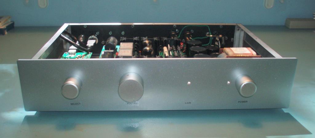
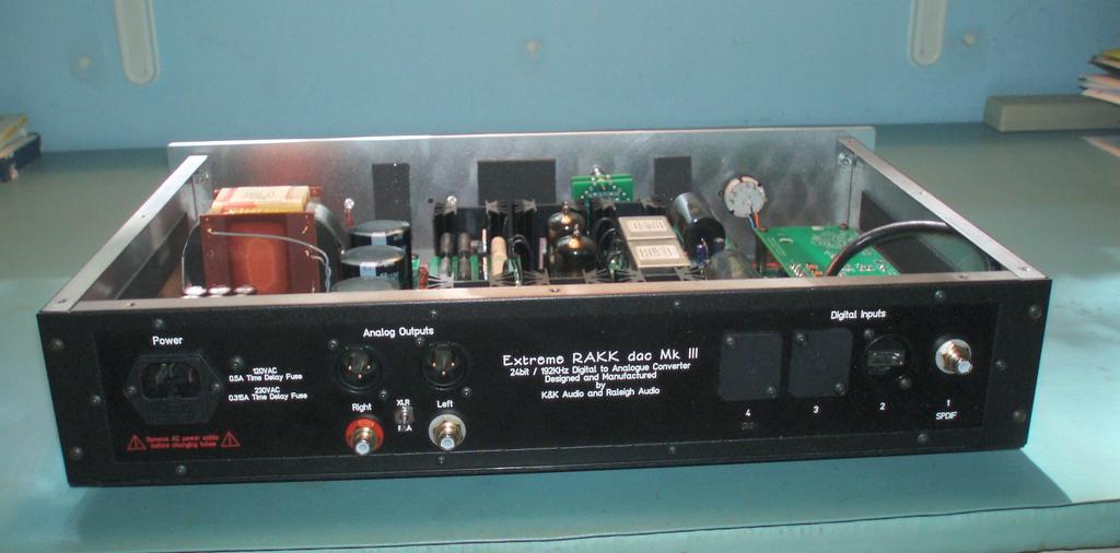
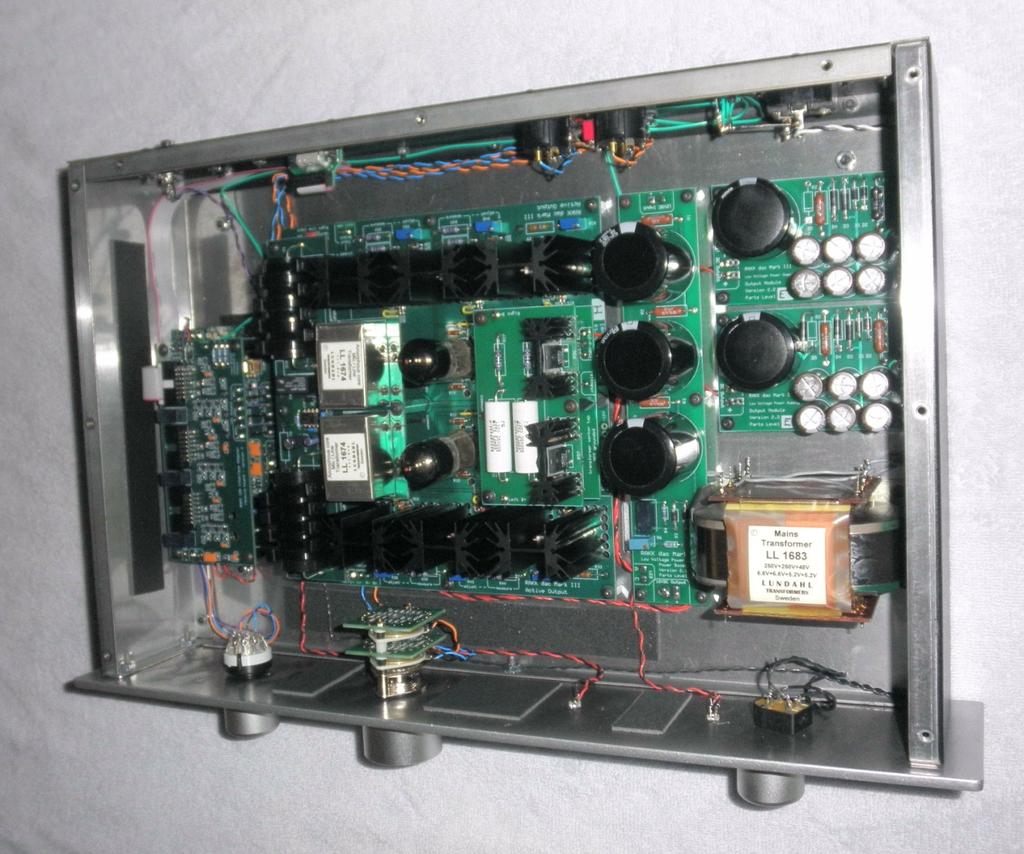
2 This completed Extreme RAKK dac has a silver face plate and knobs. A black faceplate and knobs is available. 1
3 General Information The Extreme RAKK dac is a semi-custom kit, which means that several standard offerings can be combined in different ways. You can choose to have an optional volume control and optional select switch. You can choose to have one to six inputs which may be a mix of SPDIF, AES/EBU, or I2S. These are covered in this manual although all of the possible combinations are not shown. However, those things not shown can be easily inferred from other things that are shown. This kit is relatively straightforward to build, but assumes some prior skill with a soldering iron and some knowledge of electronic components and assembly. Kit version Use this manual with the Extreme RAKK dac Mark III Use the applicable on-line manuals for component sub-assemblies. Required Tools and Supplies 150 to 250 Watt soldering gun 35 to 50 Watt soldering iron Phillips (cross point) screwdriver Volt-Ohm-Milliamp Meter Potentiometer adjustment tool (supplied) 1/16 hex (Allen) wrench (supplied) 5/64 hex (Allen) wrench (supplied) 1.5mm. hex (Allen) wrench (supplied) 2.5mm. hex (Allen) wrench (supplied) 1/4, 5/16, 1/2, 9/16 open-end wrenches Diagonal cutting pliers Long-nose pliers Wire stripper Solder Use the soldering gun only to solder the heatsink pins. Use the soldering iron for all other components. Support RAKK dac and its associated components are produced through the joint cooperation of K&K Audio and Raleigh Audio. You may contact us with questions on constructing this kit by sending an message to david@raleighaudio.com or kevin@kandkaudio.com 2
4 Warnings and Cautions Warning a high voltage power supply (200VDC) is required to make the kit operate properly. These voltages can be lethal. If you are not familiar with safe techniques for completing the installation of this kit with a high voltage power supply, then you should seek someone who is qualified to help you construct this kit safely. If you wish to review safe practice, consult the ARRL Handbook for Radio Amateurs ( or often at used book stores), which has a section on high voltage safety. Although they are usually referring to 1000v+, the techniques are still applicable. As the purchaser, you assume responsibility for safe assembly, testing, and application of this kit. Caution Use only solder that is intended for electrical circuits. Do not use acid or corrosive flux of any kind. Caution Any MOSFET is subject to damage by static electricity. Thus, the MOSFETs need special care and handling especially when the relative humidity is low. Make sure to discharge any static electrical charge from your body before handling a MOSFET. You can discharge your body by touching a water faucet or grounded electrical appliance. Soldering Notes To a large extent, the success of your kit-building endeavor depends on your ability to solder properly. Aside from experience, there are two pretty important factors in this success. The first is the soldering equipment. I recommend using a temperature controlled soldering station, although any good soldering iron of 40 watts or greater will do. There are many soldering stations on the market; I have had good experience with the moderately priced Hakko Model 936. If you do have or purchase a soldering station, or even use your existing soldering iron, I have found a chisel style tip of about 2mm-2.5mm width to be the most useful. You can use the flat part for large solder joints and the corner for small solder joints. The second factor is the selection of the solder you will use. The PC boards and most of the electrical components in the kit are lead-free, as the movement in the EU has forced manufacturers to remove the lead (and other dangerous heavy metals) from their products. Decent (notice, I didn t write good ) leadfree solder exists, such as Cardas Tri-Eutectic, but it is not so easy to use unless you have some soldering experience. Lead-free solder tends to melt in a sluggish way and the resulting solder joints are not the customary shiny silver color, so it s difficult to avoid cold solder joints without experience. It s up to you to decide what to use. Choose based on your experience. I use Cardas Quad Eutectic and can recommend it without reservation; however other high quality solders may work just as well. Take care in handling electronic solder as most of it still contains a significant quantity of lead. Wash your hands thoroughly after construction sessions and keep all kit materials well out of the reach of small children. Even though there is a component side and solder side to the board, your might find it more convenient to solder the leaded components from the component side. 3
5 Table of Contents General Information... 2 Table of Contents... 4 Assembly Instructions... 5 Pre-assemble I2S Adapter with the RAKK dac... 6 Pre-wire the printed circuit boards... 8 Pre-wire the Power Output Module (for RAKK dac)... 9 Pre-wire the Power Output Module (for I2S Adapter)... 9 Pre-wire the Power Boost Module Pre-wire the Active Output Pre-wire the RAKK dac and I2S Interface Adapter (if used) Pre-wire the Power Transformer Panel Preparation Bottom Panel Preparation Back Panel Preparation Side Panel Preparation Front Panel Preparation Panel Assembly Bottom Panel Assembly Back Panel Assembly Front Panel Assembly Final Assembly and Wiring Wire the Bottom Panel to the Back Panel Wire the Bottom Panel to the Front Panel Assemble the Panels Final Adjustments Adjust the Constant Current Sources Adjust the Front Panel LEDs Final Assembly Parts List Circuit kits Front Panel Options Input Options Extreme Kit Contents Document version history
6 Assembly Instructions Before you start, read through the instructions completely to the end. Inventory the kit contents to become familiar with the parts and to make sure you have everything. The assembly sequence is as follows: 1. Assemble all of the printed circuit boards 2. Pre-wire the printed circuit boards 3. Pre-wire the power transformer 4. Install PC boards and the power transformer on the bottom panel 5. Assemble the components on the back panel 6. Assemble the components on the front panel 7. Assemble the panels 8. Wire everything together There are two sizes of stranded wire provided with the kit, #22 and #20. The larger diameter #20 is used for power and high voltage. The smaller diameter #22 is used for signal and low voltage. Where a wire is to be connected to a PC board, prepare the end by stripping ⅛ insulation and tin the bare wire. For other connections, strip ¼ and tin the end. Where a twisted-pair is called for, provide about four or five twists per inch. Twisting wires together will shrink their length slightly so you need to take this into account. With a very few exceptions, which are explicit, insert the wire into the pad from the bottom, or solder side, of the board. Wires should be dressed neatly as close to the bottom of the enclosure as possible. Assemble the Printed Circuit Boards Depending upon the feature mix that you have chosen, the boards that you will assemble will vary. In all cases your project will include a RAKK dac, an Active Differential Output board, a Low-Voltage Power System Output Module and Power Boost Module. You may also have chosen to have a an I2S adapter and its associated power Output Module. While assembly of all of the boards is straight-forward, the Active Differential Output is the most complex. Therefore, I recommend that you leave that board until you have assembled all of the other boards. The assembly manuals for the boards include installation instructions that you will not use. Rather than using those general instructions, you will follow the specific installation instructions contained in this manual. Referring to the applicable on-line manuals, assemble the boards now. 5
7 Pre assemble I2S Adapter with the RAKK dac Skip this section if you do not have an I2S Adapter. Wire the I2S Output on the I2S Adapter 1. Mount four 1 standoffs on the bottom of the I2S Adapter and secure with 6-32 screws. 2. Insert a ½ 6-32 setscrew about half-way into each 1 standoff. 3. Install a ⅜ standoff as a nut on each of the four 1 standoffs. 4. Cut three pieces of #22 black wire, each 1⅜ long. 1⅜ is the length of the two standoffs, which may be used as a gauge. 5. Cut three pieces of #22 violet wire, each 1⅜ long. 6. Strip ¼ of insulation from each end of the wires and tin the ends by melting a little solder onto the stripped ends. 7. Insert the three black wires from the bottom of the board into the following three locations: DATA - LRCK - BCK - 8. Solder and trim the leads. 9. Insert the three violet wires from the bottom of the board into the following three locations: DATA + LRCK + BCK Solder and trim the leads. 6

8 Mount the I2S Adapter to the RAKK dac Steps preceded by a note ( ) deal with components which must be oriented properly. 1. Remove the ⅜ standoffs from the 1 standoffs on the adapter. 2. Set the I2S Adapter on top of the RAKK dac such that the I2S Output pads on the I2S Adapter align with the Input 4 I2S pads on the RAKK dac. 3. Insert the six I2S interface wires into the proper pads on the RAKK dac. 4. Install the four ⅜ standoffs as nuts to hold the two pieces together. 5. Solder the six interface wires. 7
9 Pre wire the printed circuit boards In the following steps, the wires should be inserted into the solder side of the board. Preparing a wire means to strip ⅛ of insulation from both ends of the wire and tin the ends. Because each wire has a from end and to end, and only one end is pre-wired, some pads are not wired in this section. A signal line or a function will likely have the same name on the from end as it does on the to end, therefore don t just go by the name when you install the wire. Rather, check that you are installing it on the proper board. Basically there are two ways to make a twisted pair or a multi-wire cable. The quick and easy way is to use an electric drill. So if you have a variable speed drill, all you have to do is to put the wires together in the drill chuck and turn on the drill. It might take a little practice to get the tension and speed right but once you get the knack, it is quick and easy to do. If you don t have a drill handy, the old-fashioned way of manually twisting the wires works fine. I have described how I do it here. To make a multi-wire cable, first make a twisted pair and then wrap a third wire around the twisted pair following the lay of one of the wires. Then stretch this new wire like you did the others. Follow with a fourth and fifth wire as needed. About 5% shrinkage occurs when making a twisted pair. So for example, if you wanted a 10 long twisted pair, you would make it from two 10½ wires. It would be better to err a little on the long side because you can always trim the length when you install the twisted pair. 8
10 Pre wire the Power Output Module (for RAKK dac) If you have two Power Output modules, this is the one that will be used to power the RAKK dac. Prepare a 3 #22 red/black twisted pair. Connect the red wire to the 12VDC Output + pad. Connect the black wire to the 12VDC Output - pad. Pre wire the Power Output Module (for I2S Adapter) Skip this section if you do not have an I2S Adapter. Prepare a 17 #22 red/black twisted pair. Connect the red wire to the 5VDC Output + pad. Connect the black wire to the 5VDC Output - pad. 9
11 Pre wire the Power Boost Module 1. Prepare a 13 #22 red/black twisted pair. Connect the red wire to the 12VDC Output + pad. Connect the black wire to the 12VDC Output - pad. 2. Prepare a 5¼ #22 red/black twisted pair. Connect the red wire to the LED A pad. Connect the black wire to the LED C pad. 3. If you have a 3-input I2S Adapter, prepare a 16 #22 red wire. Connect the red wire to the 12VDC Output + pad. Wrap the red wire around the 13 red/black twisted pair. 4. If you have a TOSLINK input, prepare a 19 #22 red/black twisted pair. Connect the red wire to the 12VDC Output + pad. Connect the black wire to the 12VDC Output - pad. 10
12 Pre wire the Active Output Wire the From RAKK dac inputs on the Active Output 1. Prepare a 4 #22 black wire. Connect it to the REF pad. 2. Prepare a 4 #22 orange/black twisted pair. Connect the orange wire to the R+ pad. Connect the black wire to the R- pad. 3. Prepare a 4 #22 blue/black twisted pair. Connect the blue wire to the L+ pad. Connect the black wire to the L- pad. Wire the External Mute 4. Using a craft knife cut a gap in the trace that connects the two external mute pads. 5. Prepare a 24 #22 black/black twisted pair. Connect the two wires to the two external mute pads. Wire the Volume Control on the Active Output (skip this section if you do not have a volume control) 6. Prepare a 5½ #22 blue/black twisted pair. Connect the blue wire to the volume control L+ pad. Connect the black wire to the volume control L- pad. 7. Prepare a 4½ #22 orange/black twisted pair. Connect the orange wire to the volume control R+ pad. Connect the black wire to the volume control R- pad. 11
13 Wire the Input Select on the Active Output 8. Connect a jumper wire between the two Input Select pads. Wire the Ground on the Active Output 9. Connect a 12 #20 green wire to the chassis pad. The Line Input pads are not used. 12
14 Pre wire the RAKK dac and I2S Interface Adapter (if used) Wire the Input Select on the RAKK dac and I2S Interface Adapter The RAKK dac offers four inputs: three SPDIF or AES/EBU inputs and one I2S input. Inputs 1 through 3 are the SPDIF or AES/EBU inputs and Input 4 is always the I2S input, even if you are using only a single input. There are two versions of the I2S Adapter. One offers a single input and the other provides three inputs. If you have the version that has a single input, there is no need to pre-wire it. If you have the version that has three inputs, you will need to pre-wire the input selection. Selection for Input 4 is pre-wired as part of the pre-wire for the RAKK dac. Selection for Inputs 5 and 6 are part of the pre-wire of the I2S Adapter. While there is a possibility of having six inputs, usually there will be fewer. Note that there is an arbitrary association between each input and the position of the Input Select switch that selects that input. For example, the third position on the Input Select switch may be wired to select RAKK dac input 4, or I2S input If you have chosen to use only a single input, install a jumper wire between the Input Select pad for that input and the adjacent com pad on the RAKK dac. 2. If you have chosen to use multiple inputs, you will prepare a cable. Two lengths are given for each input: the first is used if the input is on the RAKK dac and the second (in parentheses) is used if the input is on the I2S Adapter. Prepare a 12½ #22 black wire for the common. Prepare a 12½ (13½ ) #22 blue wire for the first input. Loosely twist this wire around the black wire about two or three turns for the entire length just tight enough to keep the wires together, but loose enough so the individual wires can be pulled where they are needed. Prepare a 12¾ (13¾ ) #22 orange wire for the second input. Loosely twist this wire around the other wires. If you are using a third input, prepare a 13 (14 ) #22 violet wire. Loosely twist this wire around the other wires. If you are using a forth input, prepare a 13¼ (14¼ ) #22 red wire. Loosely twist this wire around the other wires. If you are using a fifth input, prepare a 13½ (14½ ) #22 blue wire. Loosely twist this wire around the other wires. If you are using a sixth input, prepare a 13¾ (14¾ ) #22 orange wire. Loosely twist this wire around the other wires. 13
15 3. Connect the cable that you have prepared: Connect the black wire to the Input Select com pad. Connect the (shorter) blue wire to the Input Select pad selected by switch position 1. Connect the (shorter) orange wire to the Input Select pad selected by switch position 2. Connect the violet wire to the Input Select pad selected by switch position 3. Connect the red wire to the Input Select pad selected by switch position 4. Connect the (longer) blue wire to the Input Select pad selected by switch position 5. Connect the (longer) orange wire to the Input Select pad selected by switch position 6. Wire the SPDIF Lock LED (skip this step if you are not using RAKK dac inputs 1 or 2 or 3.) 4. Prepare a 13 #22 red/black twisted pair. Connect the red wire to the Lock LED A pad. Connect the black wire to the Lock LED C pad. RAKK dac inputs 1 through 3 will be pre-wired on the back panel assembly. We have found the Mute function to be of little value so that LED is not used. 14
16 Pre wire the Power Transformer For the following steps, refer to the LL1683 Data sheet. 1. Wire the transformer for your Mains line voltage: 115VAC: Connect pin 2 to pin 12 with a #20 black wire. Connect pin 4 to pin 10 with a #20 black wire. 230VAC: Connect pin 4 to pin 12 with a #20 black wire. 2. Fabricate a T-shaped AC power cable as follows: Cut a #20 black wire, 11 inches long. Do not strip the ends. Cut a #20 black wire, 19¾ inches long. Do not strip the ends. Cut a #20 white wire, 16¼ long. Do not strip the ends. Align the white wire with the longer black wire and twist them together for about 11. Align the other black wire with the other end of the white wire and twist them together for 3¾. Go back to the first pair (that you twisted to 11 ) and continue the twist until you get to the junction of the second pair. Now twist the two black wires together until you get to the end. Don t worry if the two black wires are different length you will trim them later. 3. Wire the AC cable that you just fabricated: Trim the 3¾ black/white stub to be 3½ long. Separate the end of the stub for 2¼. Trim 1¾ from the end of the black wire. Strip ¼ from the end of both wires and tin the ends. Connect the white wire to pin 10. Connect the black wire to pin 2. 15
17 4. Wire the high voltage: Make a twisted-pair from two pieces of #20 red wire, one 9½ long and one 9¾ long. Align the wires evenly at one end. Connect the longer wire at the uneven end to pin 17 on the power transformer. Connect the shorter wire to pin 15 on the power transformer. 5. Connect the center tap in the following manner: Prepare a 12 piece of #20 black wire and strip 1 from one end. Connect the tip of this end to pin 24 and then wrap the bare wire around pin 22. Solder both pins. Dress this wire towards pin 15 and wrap it around the red twisted pair following the lay of the twist. Trim the black wire to be the same length as the two red wires. 6. Wire the filament power Make a twisted-pair from two pieces of #20 grey wire, one 5 long and one 7¼ long. Align the wires evenly at one end. Connect the longer wire at the uneven end to pin B1 on the power transformer. Connect the shorter wire to pin B6 on the power transformer. 7. Wire the RAKK dac AC power Make a twisted-pair from two pieces of #20 grey wire, one 7 long and one 9¾ long. Align the wires evenly at one end. Connect the longer wire at the uneven end to pin B7 on the power transformer. Connect the shorter wire to pin B4 on the power transformer. Skip this step if you do not have an I2S Adapter. 8. Wire the I2S Adapter AC power Make a twisted-pair from two pieces of #20 grey wire, one 4¾ long and one 6⅛ long. Align the wires evenly at one end. Connect the longer wire at the uneven end to pin B8 on the power transformer. Connect the shorter wire to pin B3 on the power transformer. 16

18 Panel Preparation Cut one 10 x 2 piece of damping material into two pieces: 10 x 1. Cut another 10 x 2 piece of damping material into three pieces: Two, 8 x 1 and one, 2 x 2. Cut the remaining 10 x 2 piece of damping material into four pieces: Two, 4 x 1, one, 8 x 1 and one, 2 x 2. Bottom Panel Preparation Note that the lip on the bottom panel points towards the inside. 1. Install the four feet in their holes close to the corners of the panel. Use a 6-32 x ½ screw, flat washer and Kep nut on each foot. Place the washer between the head of the screw and the rubber foot. 2. Install one piece of 8 x 1 damping material on the inside of the bottom panel, centered between the vents and the lip. 3. Install one piece of 4 x 1 damping material on the inside of the bottom panel, next to and centered on the left side of the vents. 4. Install one piece of 4 x 1 damping material on the inside of the bottom panel, about 1 away from and centered on the right side of the vents. Note that the bottom panel in the picture above has lines drawn to show where the transformer and circuit boards will be mounted. 17

19 Top Panel Preparation 1. Place the top panel such that the inside surface of the panel faces up and the edge with the lip (front) is away from you. 2. Install one piece of 10 x 1 damping material on the inside of the top panel, centered between the vents and the lip. 3. Install one piece of 10 x 1 damping material on the inside of the top panel, centered between the back of the panel and the vents, but closer to the vents so as not to interfere with attaching the back panel. Back Panel Preparation The back panel consists of two parts: an open frame that attaches to the other panels and a customized insert that contains the jacks. Place the insert inside the frame and secure them with ten 4-40 x ⅜ screws and ten Kep nuts. Because two panels being clamped together inhibit vibration resonances, no damping treatment is required for this panel. 18
20 Side Panel Preparation 1. Install an 8 x 1 piece of damping material centered on the inside of the left panel. 2. Install an 8 x 1 piece of damping material centered on the inside of the right panel. Front Panel Preparation The position of damping material for the front panel will vary depending upon the switches and controls that you have chosen. Install the two remaining 2 x 2 pieces of damping material on the inside of the front panel. Position them evenly and you may wish to cut one or both pieces to provide a more even distribution. Make sure that there is at least ⅝ between the damping material and either the top edge or bottom edge of the panel. 19
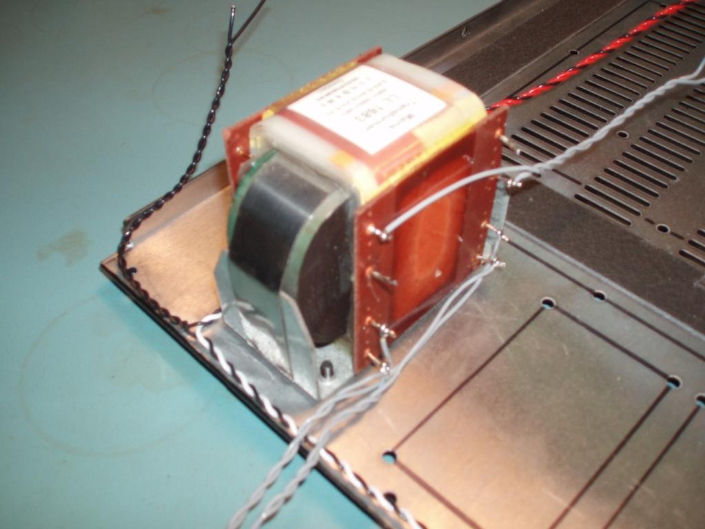
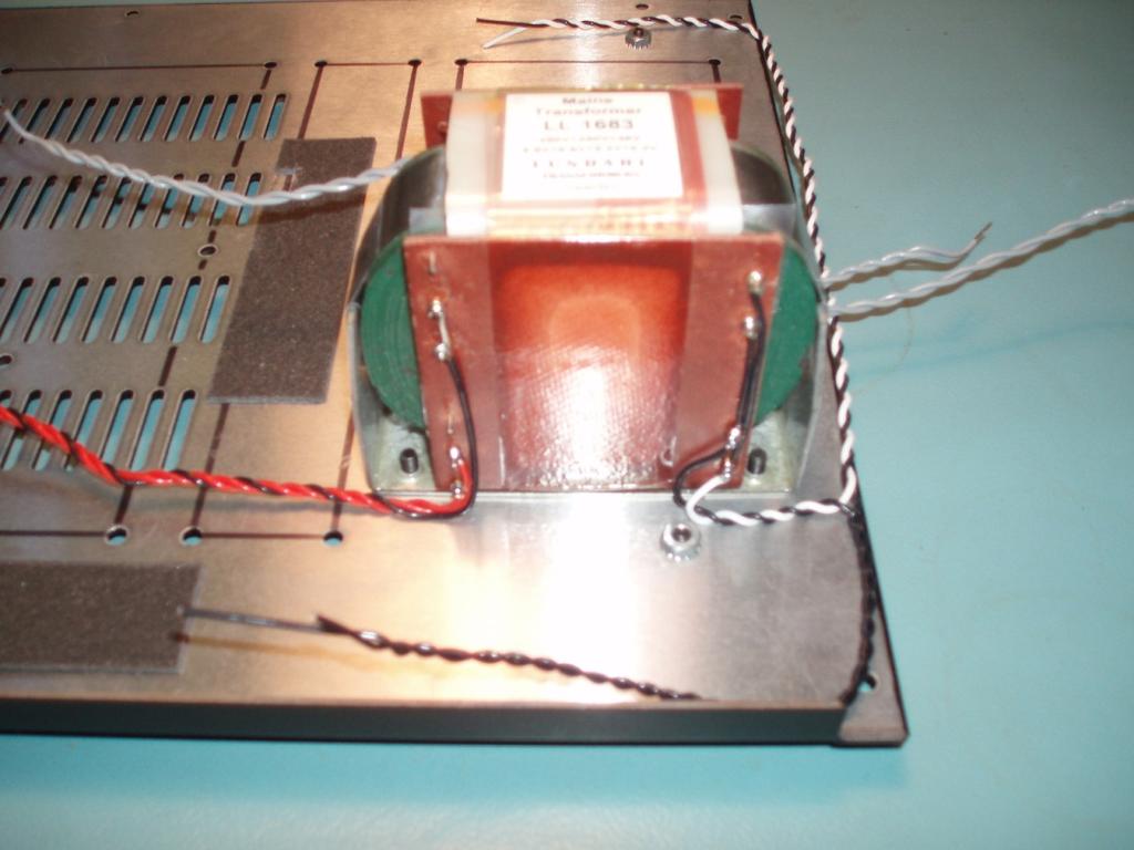
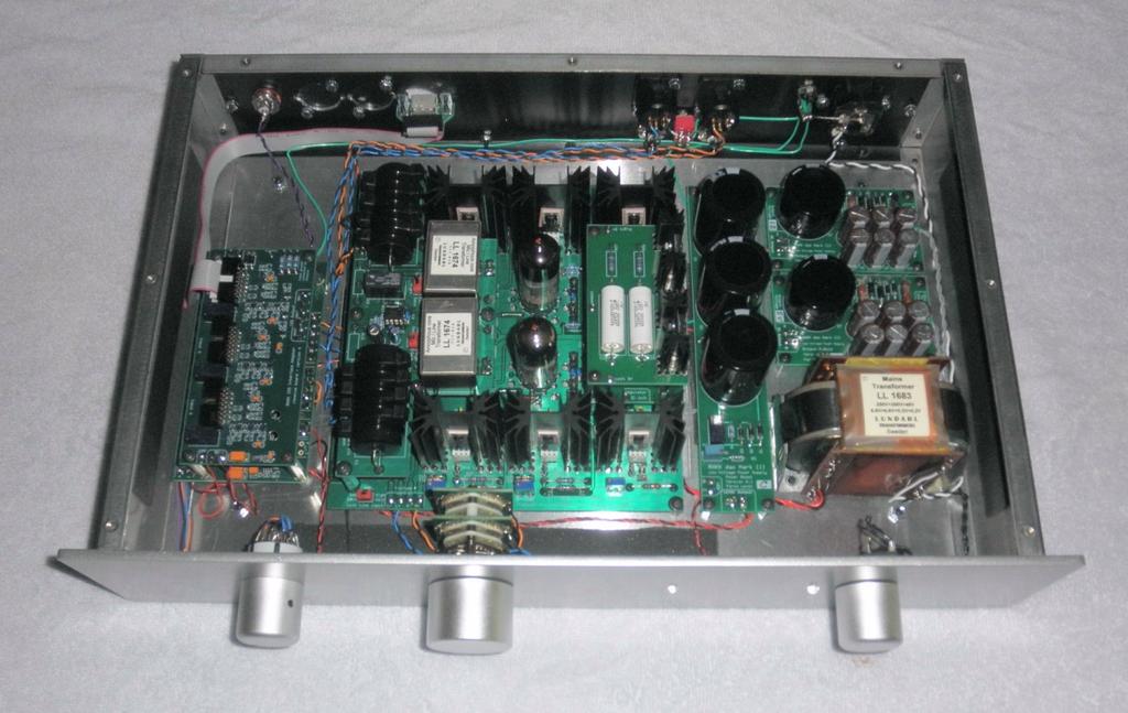
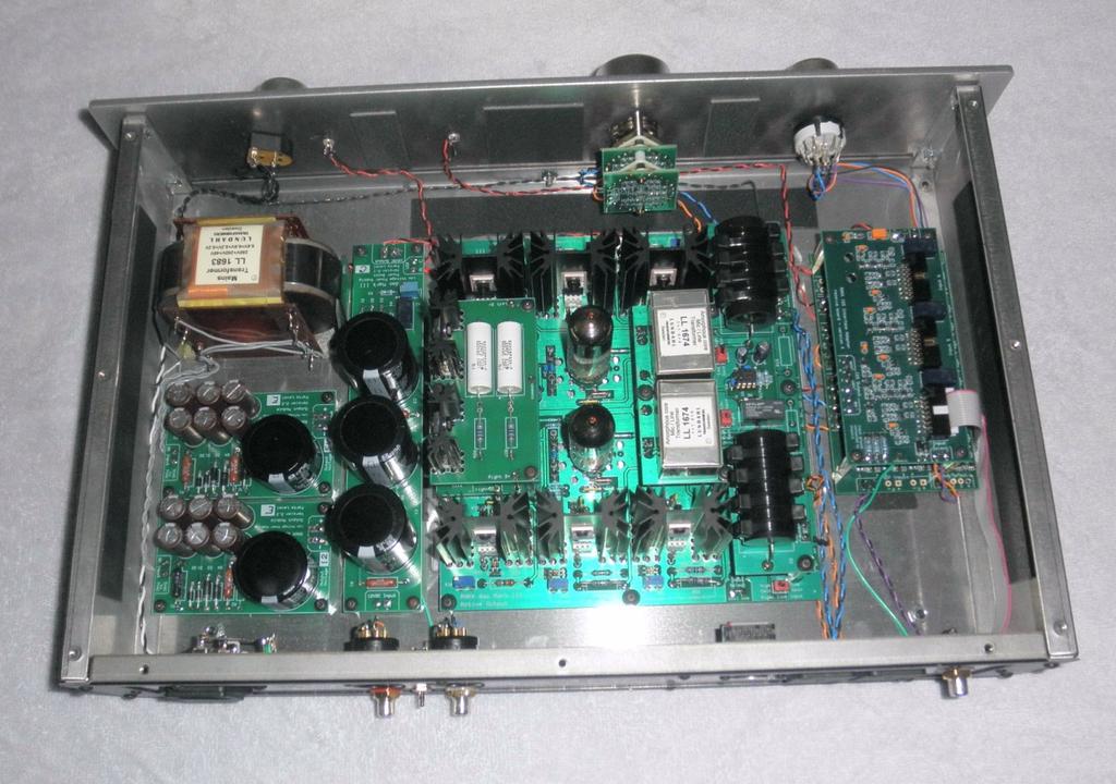
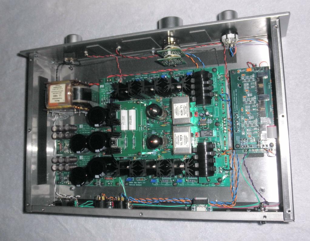
21 Panel Assembly Bottom Panel Assembly Steps preceded by a note ( ) deal with components which must be oriented properly. TIP To ease the alignment of the mounting holes with standoffs, slightly loosen the standoffs from the board, install the screws through the bottom panel into the standoffs and then re-tighten the standoffs. Mount the power transformer 1. Mount the LL1683 transformer in its location using the four 4mm metric screws. Orient the transformer such that the high-voltage (shorter) pins are towards the front of the panel. The front of the panel has the lip. Dress the white/black twisted pair toward the edge of the panel. Then the white/black twisted pair will go towards the rear of the panel and the black/black twisted pair will go to the front of the panel. Dress the grey twisted pair that will attach to the Power Output Module toward the edge of the panel. If you have a second grey twisted pair that will attach to a Power Output Module, dress it toward the edge of the panel. Dress the grey twisted pair that will power the filaments toward the center of the panel. Dress the red/red/black twisted trio toward the center of the panel. 20
22 21

23 Mount the Power Output module for the RAKK dac. Remember, if you assembled two Power Output modules, they were personalized with different ballast resistors and different voltages. 2. Place the Power Output module for the RAKK dac in its location, in line with the transformer, but close to the rear of the panel. Orient the board such that the AC Input is closest to the edge of the panel. Do not secure the board yet. 3. Dress the grey twisted pair that is connected to transformer pins B4 and B7 along the edge of the panel to the Power Output Module. Connect that grey twisted pair to the AC Input pads. 4. Secure the board with four 6-32 x ¼ screws. 22

24 Mount the Power Output module for the I2S Adapter Skip this section if you do not have an I2S adapter. 5. Place the Power Output module for the adapter in its location, between the transformer and the other Power Output module. Orient the board such that the AC Input is closest to the edge of the panel. Do not secure the board yet. 6. Dress the grey twisted pair that is connected to transformer pins B3 and B8 along the edge of the panel to the Power Output Module. Connect that grey twisted pair to the AC Input pads. 7. Secure the board with four 6-32 x ¼ screws. 8. Dress the wires: Dress the red/black twisted pair directly across the bottom panel. 23

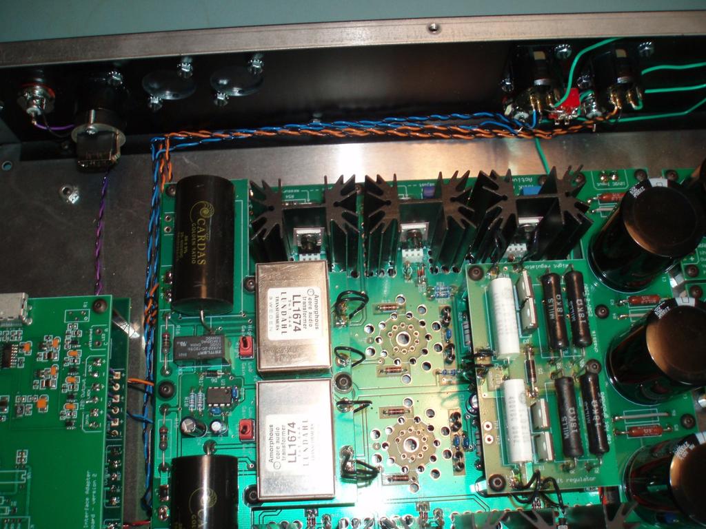
25 Mount the Active Output board 9. Mount the Active Output board in its location in the center of the chassis. Orient the board such that the power input pads are closest to the power transformer. Do not secure the board yet. 10. Locate the grey twisted pair that is connected to transformer pins B1 and B6. Connect this twisted pair to the 6.3VAC pads. 11. Locate the red twisted pair that is connected to transformer pins 15 and 17 and has a black wire wrapped around it. These three wires will be connected to the 250V-0-250V pads. Connect the two red wires to the outer pads. Connect the black wire to the center pad. 12. Secure the board with thirteen 6-32 x ¼ screws. 13. Dress the wires: Dress the twisted pairs for the volume control towards the front of the panel. Dress the twisted pairs for the RAKK dac towards the edge of the panel. Dress the green wire from the chassis pad towards the rear of the panel. 24

26 Mount the Power Boost board 14. Mount the Power Boost board in its location between the Active Output board and the transformer. Orient the board such that the 12VDC Output is towards the front of the panel. Do not secure the board yet. 15. Locate the red/black twisted pair from the RAKK dac Power Output board. Connect the red wire to the 12VDC Input + pad. Connect the black wire to the 12VDC Input - pad. 16. Secure the board with five 6-32 x ¼ screws. 17. Dress the wires: Dress the shorter red/black twisted pair towards the front of the panel. Dress the longer red/black twisted pair(s) along the edge of the Active Output board toward the far edge of the panel. 25
27 Mount the RAKK dac 18. Mount the RAKK dac in its location next to the Active Output board. Orient the board such that the Output pads are closest to the Active Output board. Do not secure the board yet. 19. Locate the orange/black twisted pair, blue/black twisted pair and black wire that are connected to the From RAKK dac pads on the Active Output. These will be connected to the Output pads on the RAKK dac. Connect the orange wire to the R+ pad and connect the associated black wire to the R- pad. Connect the blue wire to the L+ pad and connect the associated black wire to the L- pad. Connect the black wire to the REF pad. 20. Locate the 13 red/black twisted pair that is connected to the Power Boost module 12VDC Output. It will be connected to the 12V pads on the RAKK dac. Connect the red wire to the + pad. Connect the black wire to the - pad. 26

28 Wire the I2S Adapter power Skip this section if you do not have an I2S Adapter. 21. Locate the red/black twisted pair that is connected to the 5VDC Output pads on the Output module that you assembled for the I2S Adapter. It will be connected to the 5V pads on the I2S Adapter. Connect the red wire to the + pad. Connect the black wire to the - pad. 22. If you have a three-input I2S Adapter, locate the red wire from the 12V Power Boost board. Connect this wire to the 12V pad on the I2S adapter. 23. Dress the Input Select wires along the side to the front of the panel. Dress the Lock twisted pair to the front of the panel and then towards the other end of the panel. 27

29 Back Panel Assembly You may have as few as one or as many as six input jacks. There are several types of input jacks and here are some general guidelines for mounting the jacks: Mount the jacks from the inside of the panel. The large, XLR-size, jacks are secured with two 4-40 x ⅜ screws and nuts. Orient XLR jacks such that the center pin is on the bottom. XLR inputs use female jacks (with a tab), XLR outputs use male jacks. The HDMI jack should be mounted with the widest part of the connector closest to the top of the panel. The standard output jack arrangement is for a pair of RCA jacks and a pair of XLR jacks. An associated switch selects the proper grounding for the jacks. This standard is assumed for these instructions. 28
30 Mount the jacks and hardware: 1. Install the digital input jacks that you will be using. 2. If you have chosen to have unused input holes for future expansion, install filler plugs in those locations. 3. Install a male XLR connector in each of the two output locations. 4. Mount an RCA jack in each of the two output locations. Position the red washer on the outside of the right jack and the white washer on the outside of the left jack. 5. Install the DPDT toggle switch in the RCA/XLR location. Position the switch so the toggle alternates between the RCA and XLR. 6. Install the fuse in the power connector. Note that there is also a place for the spare fuse in the fuse holder. 7. Install the power connector from the outside of the panel. Orient the connector such that the fuse is on the bottom, and secure with two 4-40 x ⅜ screws and nuts. 8. Install the solder lug on the inside of the panel, in the hole adjacent to the power connector. Secure with a 4mm screw and nut. Orient the solder tab away from the power connector and form the solder tab at a 90-degree angle away from the panel. Wire the power connector: 9. Wire the safety ground: This wire will be used a single-point chassis ground buss to which other wires are soldered. Strip the insulation from the 2 piece of #18 solid wire so that it is bare. Connect one end of this wire to the top (center from the outside) terminal on the power connector. Dress the wire straight to the side and then down toward the solder lug. Connect the wire to the tab on the solder lug. Solder both ends of the wire. Tin the wire by flowing solder over the whole length. The hot and neutral pins will be wired later. 29
31 Wire the chassis ground connections: 10. Connect a 5 #20 green wire from both center pins on the RCA/XLR switch to the ground buss. Solder both ends and dress the wire along the bottom edge of the panel. 11. If you have an I2S Adapter, prepare a 20 #20 green wire. Connect it to the ground buss. The next three steps deal with XLR jacks. Note that the XLR jacks have an extra silver-colored metal tab adjacent to pin 1. This tab is connected to the body of the jack and may be used to make a chassis ground connection. 12. Connect a jumper wire from pin 1 on the left output XLR connector to the adjacent ground tab. Solder both ends. 13. Connect a jumper wire from pin 1 on the right output XLR connector to the adjacent ground tab. Solder both ends. 14. If you have XLR Input connectors, connect a jumper wire from pin 1 on each input XLR connector to the adjacent ground tab. Solder both ends. Earlier versions of these instructions had the XLR chassis connections made with green wires to the ground buss. These new instructions are not only easier but also more effective; therefore ignore any pictures in this document showing green wire grounds between the XLR jacks and the ground buss. 30

32 Wire the output jacks: 15. Prepare two twisted pairs as follows: Make a twisted pair from a 16 piece of orange #22 wire and a 18¾ piece of black #22 wire. Measure and trim the uneven end such that the black wire is 2¾ longer than the orange wire. Do not worry about the other end; you will trim it later. On the uneven end, strip 2½ from the black wire and tin just the tip. Strip about ⅛ from the end of the orange wire and tin the end. Likewise, make a twisted pair from an 18 piece of blue #22 wire and a 20¾ piece of black #22 wire. Measure and trim the uneven end such that the black wire is 2¾ longer than the blue wire. Do not worry about the other end; you will trim it later. On the uneven end, strip 2½ from the black wire and tin just the tip. Strip about ⅛ from the end of the blue wire and tin the end. 31

33 16. Wire the right output RCA jack: You will now install the black/orange twisted pair that you just made. On the uneven end, insert the end of the black wire into the switch terminal that is closest to the right XLR jack. Solder the terminal and wire. Wrap the long stripped end of the black wire around the shell of the right RCA jack and solder it. You might want to use a soldering gun for this operation. Solder the orange wire to the center pin. 17. Wire the left output RCA jack: You will now install the black/blue twisted pair that you just made. On the uneven end, insert the end of the black wire into the switch terminal that is closest to the left XLR jack. Solder the terminal and wire. Wrap the long stripped end of the black wire around the shell of the left RCA jack and solder it. You might want to use a soldering gun for this operation. Solder the blue wire to the center pin. 32
34 18. Wire the right output XLR jack: Prepare a twisted pair from a 16 piece of orange wire and a 16 piece of black wire. The resultant twisted pair will be about 15 long. Strip about ⅛ from both wires on one end and tin the ends. Connect the black wire to pin 3 of the right output XLR jack. Connect the orange wire to pin 2 of the right output XLR jack. 19. Wire the left output XLR jack: Prepare a twisted pair from an 18 piece of blue wire and an 18 piece of black wire. The resultant twisted pair will be about 17 long. Strip about ⅛ from both wires on one end and tin the ends. Connect the black wire to pin 3 of the left output XLR jack. Connect the blue wire to pin 2 of the left output XLR jack. 20. Wire each SPDIF input (RCA jack) (if used) as follows: Make a twisted pair from an 8 piece of violet #22 wire and a 10 piece of black #22 wire. On the uneven end, strip 1¾ from the black wire and tin just the tip. Wrap the long stripped end of the black wire around the shell of the input RCA jack and solder it. Connect the violet wire to the center pin. 21. Wire each AES/EBU input (XLR jack) (if used) as follows: Prepare an 8 #22 violet/black twisted pair. Connect the violet wire to pin 2 and the black wire to pin 3. You previously wired a jumper between pin 1 and the adjacent tab. 22. Wire the TOSLINK input (if used) as follows: Prepare an 8 #22 violet/black twisted pair. Connect the violet wire to SPDIF + and the black wire to SPDIF. You will wire the power later. 33
35 Front Panel Assembly Suggestion: You may want to place a towel on your work surface to ensure that you don t scratch the panel. Skip the steps involving the select switch and volume control if you do not have those options. 1. Notice that the two LEDs have one lead that is longer than the other. This identifies the functions of the leads the longer lead is the anode and the shorter lead is the cathode. You will now shorten both leads while keeping the length distinction. Cut the shorter lead on each LED to be ¼ long Cut the longer lead on each LED to be ⅜ long 2. Mount the Power-On LED in its hole and secure it in place with a drop of adhesive. 3. Mount the SPDIF Lock LED in its hole and secure it in place with a drop of adhesive. 4. Install the Power on/off switch in its location on the right end (from the front) of the panel using the supplied nut. Tighten the nut snug but be careful to not over-tighten the nut because the thread is plastic and it may strip. 5. Install the input select switch in its location on the left end (from the front) of the panel using the supplied nut. Tighten the nut snug but be careful to not over-tighten the nut because the thread is plastic and it may strip. 6. Install the volume control in the remaining hole. 34
36 Final Assembly and Wiring Wire the Bottom Panel to the Back Panel Position the back panel on the back of the bottom panel and secure it with three 6-32 screws. Trim the length of these wires as needed in the following steps. Wire the AC Power and Ground 1. Dress the loose green wire from the ground buss close to the chassis and connect it to the chassis pad on the I2S Adapter. 2. Dress the green wire from the chassis pad on the Active Output close to the chassis and connect it to the ground buss. 3. Dress the power cable that is connected to transformer pins 2 and 10 as follows: Dress the cable to the edge of the panel. Dress the white/black twisted pair along the edge of the bottom panel toward the back of the panel. Dress the black twisted pair along the edge of the bottom panel toward the front of the panel. 4. Connect the white/black cable to the power connector as follows: Trim ½ from the end of the black wire. Strip ¼ from the end of both wires and tin the ends. Connect the white wire to the center pin. Connect the black wire to the bottom pin. 35

37 Wire the RAKK dac Inputs 5. If you have chosen to have an SPDIF or AES/EBU Input 1, connect the violet/black twisted pair from that jack to the Input 1 pads on the RAKK dac. Connect the violet wire to the + pad and the black wire to the - pad. 6. If you have chosen to have an SPDIF or AES/EBU Input 2, connect the violet/black twisted pair from that jack to the Input 2 pads on the RAKK dac. Connect the violet wire to the + pad and the black wire to the - pad. 7. If you have chosen to have an SPDIF or AES/EBU Input 3, connect the violet/black twisted pair from that jack to the Input 3 pads on the RAKK dac. Connect the violet wire to the + pad and the black wire to the - pad. 8. If you have chosen to have a TOSLINK, connect the 19 red/black twisted pair from the Power Boost Module jack to the 12V pads on the TOSLINK board. Connect the red wire to the + pad and the black wire to the pad. 9. Secure the RAKK dac with four 6-32 screws. 36
38 Wire the I2S Adapter Skip this step if you do not have a I2S Adapter 10. Dress the flat cables close to the chassis and connect them to the appropriate inputs on the I2S Adapter. Wire the Outputs 11. Connect the orange/black twisted pair from the Right Output RCA jack to the Right Output pads on the Active Output. Connect the orange wire to the R+ pad and the black wire to the R- pad. 12. Connect the orange/black twisted pair from the Right Output XLR jack to the Right Output pads on the Active Output. Connect the orange wire to the R+ pad and the black wire to the R- pad. 13. Connect the blue/black twisted pair from the Left Output RCA jack to the Left Output pads on the Active Output. Connect the blue wire to the L+ pad and the black wire to the L- pad. 14. Connect the blue/black twisted pair from the Left Output XLR jack to the Left Output pads on the Active Output. Connect the blue wire to the L+ pad and the black wire to the L- pad. 37
39 38

40 Wire the Bottom Panel to the Front Panel Lay the front panel down adjacent to the bottom panel where it will be installed. Trim the lengths of the wires as needed in the following steps. 39

41 Wire the Volume Control (skip this section if you do not have a volume control) 1. Connect the twisted pairs from the volume control pads on the Active Output board to the volume control as follows: Connect the blue wire to the tab extending from the switch wafer closest to the front panel. Connect the associated black wire to the com pad on the board closest to the front panel. Connect the orange wire to the tab extending from the switch wafer closest to the back of the switch. Connect the associated black wire to the com pad on the board closest to the back of the switch. 40
 blue wire to the 1 tab.")
42 Wire the Select Switch (skip this section if you do not have a select switch) 2. Connect the cable from the Input Select pads on the RAKK dac as follows: Connect the black wire to the A tab of the Select switch. Connect the (shorter if two) blue wire to the 1 tab. Connect the (shorter if two) orange wire to the 2 tab. Connect the violet wire to the 3 tab. Connect the red wire to the 4 tab. Connect the (longer if two) blue wire to the 5 tab. Connect the (longer if two) orange wire to the 6 tab. 41

43 Wire the Power Switch The power switch has four terminals. One pair will be used to control the power on/off and the other pair will be used to provide a fast mute for power off. 3. Connect the #20 black twisted pair from the power transformer to the two terminals on the power-on switch that are closest to the bottom of the panel. 4. Connect the #22 black twisted pair from the Active Output to the two terminals on the power-on switch that are closest to the top of the panel. 42

44 Wire the Power-on LED 5. Locate the red/black twisted pair from the Power Boost board. 6. Solder the wires to the LED leads about ⅛ from the body of the LED. Connect the red wire to the anode. The anode is the longer of the two leads. Connect the black wire to the cathode. Wire the SPDIF Lock LED 7. Locate the red/black twisted pair from the RAKK dac Lock LED pads. 8. Solder the wires to the LED leads about ⅛ from the body of the LED. Connect the red wire to the anode. The anode is the longer of the two leads. Connect the black wire to the cathode. 43


45 Mount the Front Panel 8. Mount the front panel onto the bottom panel. Remove the plastic covers from the studs now. The stud in the center bottom of the front panel fits into the hole in the lip of the bottom panel. Secure the panel with a 6-32 KEP nut on the center stud only finger-tight. 9. Neatly dress the wires along the bottom panel close to the front panel. 44
46 Assemble the Panels The back panel has been temporarily mounted on the bottom panel so that the two panels could be wired together. Likewise, the front panel has been temporarily mounted on the bottom panel. You will now permanently mount and adjust all of the panels so that they fit together nicely. You will tighten the screws in a specific order. As you do, ensure that the side panels and back panel stay in alignment with the edges of the bottom panel. This is a two-step process with the screws first being slightly tightened to the extent that the side panels can be moved sideways with some force, but won t return on their own to their previous position. I will use the term snug up for this first step. Then, when everything is snug and in alignment, the screws will be tightened firmly. Use 6-32 x ¼ button head screws for assembling the bottom, sides and back panels. Use 6-32 x ¼ Phillips head screws for securing the top panel. Position the back panel 1. Slightly loosen and then snug up the three screws securing the back panel to the bottom panel. 2. Align the surface of the back panel with the edge of the bottom panel. 3. Make sure that the left and right edges of the back panel align with the left and right edges of the bottom panel. 4. Firmly tighten the three screws securing the back panel to the bottom panel. Position the two side panels on the ends of the bottom panel 1. Orient the side panels such that the ends of the side panels with the open holes are at the front and the ends of the panels with the insert nuts are at the back. 2. The studs on each end of the front panel fit into the holes on the ends of the side panels. 3. Install two screws through the back panel into each side panel. Leave these four screws slightly loose. 4. Install three screws through the bottom panel into each side panel. Leave these six screws slightly loose. 5. For each side panel, align the back edge of the side panel with the outside edge of the back panel and snug up the screws that secure the back panel to the side panel. 6. For each side panel, align the surface of the side panel with the edge of the bottom panel and snug up the screws that secure the side panels to the bottom panel. 45
47 Position the Front panel 1. Tighten the KEP nut in the middle of front panel while lifting the front panel so it contacts the tops of the mounting holes. This ensures that it's straight with respect to the shelf it will be sitting on. 2. Secure the front panel to the side panels with four KEP nuts. Snug up these four nuts. Now with all of the screws and nuts snug, a side panel can be moved with some force, if need be. Position the top panel 1. Place the top panel on the top of the unit and check that the holes in the top panel are centered over the screw holes in the side panels and back panel. 2. Adjust the side panel alignment at the front by moving the top of the side panel left or right as is necessary to make the holes in the top panel align properly with the holes in the side panels. Secure the back, side and bottom panels 1. Install nine screws in the top panel. Firmly tighten these screws. 2. Firmly tighten the four screws securing the back panel to the side panels. 3. Firmly tighten the three screws securing each side panel to the bottom panel. 4. All screws should now be firmly tightened. Secure the front panel 1. Remove the top panel. 2. Firmly tighten the four KEP nuts that are securing the front panel to the side panels. 3. Place the top panel on the top of the unit and check that the holes in the top panel are still centered over the screw holes in the side panels and back panel. 4. Set the top panel aside for now. You will install it after the final electrical adjustments are made. 46
48 47
49 48
50 49
51 50
52 Final Adjustments Adjust the Constant Current Sources The adjustments that you are about to make on the Active Output board interact. Therefore, the first time you may have to alternate adjustments to get them in range. 1. Install a 6N6P tube in locations V1 and V2. 2. Power on the Extreme RAKK dac and allow it to warm up for about one minute. 3. Adjust the Left B+ to be 200V. Measure the voltage from the Left B+ pad on the power board to the ground buss. Adjust R Adjust the Right B+ to be 200V. Measure the voltage from the Right B+ pad on the power board to the ground buss. Adjust R Measure the voltage across each of the four CCS current sense resistors and adjust the associated potentiometers for 240mV across its resistor. Measure Adjust Voltage R39 R V R44 R V R49 R V R54 R V 6. Allow the unit to warm up for about 15 minutes and then check and re-adjust the above six adjustments. 51
53 Adjust the Front Panel LEDs 7. Adjust the Power On indicator. Power the unit on Adjust the potentiometer on the Power Boost Module for the desired brightness of the LED. 8. Adjust the SPDIF Lock Indicator. Attach a CD transport to the SPDIF input Select that input Play a CD Adjust the potentiometer on the RAKK dac for the desired brightness of the LED. Final Assembly 1. You may optionally choose to apply a tiny drop of Loctite to the screws that hold the circuit boards in place both top and bottom. This will ensure that the screws will not work loose over time or during shipment. Screws and nuts that have star lock washers do not need Loctite. 2. Position the top panel on the top of the unit and secure with nine 6-32 x ¼ Phillips head screws. Tighten these screws. 3. Install the knobs. Align the knobs and tighten the setscrews using a 1.5mm. hex wrench. 4. Apply optional labeling tape to the front panel. Congratulations! You have finished the assembly and installation. Enjoy the music and be aware that the character and quality of the sound will improve with time. The first 100 hours are most noticeable so hold off making evaluations until after that. 52
54 Parts List Circuit kits Refer to the parts list for each of these kits. The following kits are provided. RAKK dac Mark III Active Differential Output Low Voltage Power System Power Output Module Low Voltage Power System Power Boost Module Front Panel Options The front panel will be customized for the options that you have chosen. Volume Control Part Description Qty volume control 1 knob 1 Input Select switch Part Description Qty select switch 1 knob 1 53
55 Input Options The back panel will be customized for the options that you have chosen. SPDIF Input Part Description Qty RCA jack 1, 2 or 3 LL1572 pulse transformer 1, 2 or 3 AES/EBU Input Part Description Qty XLR jack female, with tab 1, 2 or 3 Screw 4-40 x ⅜ 2, 4 or 6 Kep nut 4-40 (with star washer) 2, 4 or 6 LL1574 pulse transformer 1, 2 or 3 I2S Input Part Description Qty I2S Interface Adapter circuit board (either 1 input or 3 input) 1 standoff 6-32 x 1 4 setscrew 6-32 x ½ 4 LVPS circuit board and parts 1 Output Module kit HDMI jack with cable 1, 2 or 3 screw 4-40 x ⅜ 2, 4 or 6 54
56 Extreme Kit Contents In addition to the parts in the circuit kits and options listed above, these parts are provided: Mechanical Parts Part Description Qty Chassis set Top, bottom, front, back frame, two sides 1 Back Panel custom 1 Power switch Rotary, 1 Knob For power switch 1 AC inlet module Black with three prongs 1 Fuse 0.5A, 250V 5 x 20mm for 115VAC 0.315A, 250V 5 x 20mm for 230VAC 2 RCA jack Cardas 2 XLR jack, male Black with three prongs 2 Switch, toggle For RCA/XLR 1 LED blue 2 Power transformer LL Foot Damping, black 4 Damping material 2 by 10 with adhesive backing 3 55
57 Wire List From this, twisted pairs and individual pieces are called out in the individual assembly steps. Twisted wires are best made using a small electrical drill to do the twisting. Between 4 and 5 twists per inch is good. Be sure not to twist all the wire of a given color as some individual pieces are needed as well as twisted ones. Remember the twisting will slightly shrink the length so take this into account. Part Description Qty Wire, 20 gauge white 20 black 52 red 21 green 41 grey 44 Wire, 22 gauge black 287 blue 80 red 111 orange 77 violet 45 Wire, 18 gauge solid 2 56
58 Hardware List Part Description Qty Screw 4-40 x button head 10 for the back panel plus 2 for each connector Screw 6-32 x 0.25 button head 17 Screw 6-32 x 0.5 button head 4 Screw 6-32 x 0.25 Phillips head 9 Screw 4mm x 8mm button head 5 Nut 4-40 Kep nut (with star washer) 10 for the back panel plus 2 for each connector Nut 6-32 Kep nut (with star washer) 9 Nut 4mm machine nut 1 Washer 6-32 flat washer 4 Ground lug 4mm 1 Stand-off 6-32 x Adjustment tool for potentiometers note 1 Wrench Hex, 5/64 for 6-32 screws note 1 Wrench Hex, 1/16 for 4-40 screws note 1 Wrench Hex, 1.5mm, for knobs 1 Wrench Hex, 2.5mm for 4mm screws 1 Notes: 1. 1/16 and 5/64 wrenches and the adjustment tool are included with the Active Output parts. 2. The 1/16 wrench is almost the same size as the 1.5mm wrench, however even the small difference is important for properly fitting the screws
The ability to make basic voltage and resistance measurements using a digital multimeter
 Congratulations on your purchase of a new OneShot chassis! The PC01 OneShot combines a rugged enclosure, power supply, and discrete instrument DI in a compact 1/4U package. A few minutes of assembly are
THE AGGRESSOR (K-995)
") THE AGGRESSOR (K-99) TONE VOLUME DISTORTION MID-SHIFT SWITCH LED The Aggressor Distortion Pedal Modkitsdiy.com 9 VDC CENTER (-) ADAPTER TO AMP IN FROM GUITAR OUT Unplug when not in use to save battery
THE AGGRESSOR (K-99) TONE VOLUME DISTORTION MID-SHIFT SWITCH LED The Aggressor Distortion Pedal Modkitsdiy.com 9 VDC CENTER (-) ADAPTER TO AMP IN FROM GUITAR OUT Unplug when not in use to save battery
Pacific Antenna 20 and 40M Lightweight Dipole Kit
 Pacific Antenna 20 and 40M Lightweight Dipole Kit Antenna diagram showing configuration and lengths when assembled 7 8 16 9 16 9 Description The Pacific Antenna lightweight dual band dipole kit provides
OpenROV. Guide 3 - Electronics. We will now move to the assembly of the electronics that will control the ROV. Written By: OpenROV
 OpenROV Guide 3 - Electronics We will now move to the assembly of the electronics that will control the ROV. Written By: OpenROV 2017 openrov.dozuki.com Page 1 of 33 INTRODUCTION We will introduce soldering
Specimen Products Single Ended Stereo Amp Instruction Book
 Specimen Products Single Ended Stereo Amp Instruction Book Specimen tube amplifier designs are informed by decades of servicing and building musical instrument amps. As a result of being subjected to the
Manual Version July 2007
 Manual Version 1.2 - July 2007 Page 1 Table of Contents Section1: M3 Phono Board Build...3 Phono Board Parts List...3 Preparation...4 Fitting the Valve Bases...6 Installing the Resistors...7 Starting the
Assembly Instructions for the 1.5 Watt Amplifier Kit
 Assembly Instructions for the 1.5 Watt Amplifier Kit 1.) All of the small parts are attached to a sheet of paper indicating both their value and id. 2.) Leave the parts affixed to the paper until you are
THE RING RESONATOR (K-975)
") THE RING RESONATOR (K-975) OUTPUT BOOST The Ring Resonator An Octave Up Fuzz Modkitsdiy.com 9 VDC CENTER (-) ADAPTER TO AMP IN FROM GUITAR OUT Unplug when not in use to save battery life. Use these instructions
THE RING RESONATOR (K-975) OUTPUT BOOST The Ring Resonator An Octave Up Fuzz Modkitsdiy.com 9 VDC CENTER (-) ADAPTER TO AMP IN FROM GUITAR OUT Unplug when not in use to save battery life. Use these instructions
Starving Student II. Starving Student II. SS2 guide. Written By: 6L guides.diyaudio.com/ Page 1 of 24
 SS2 guide Written By: 6L6 2019 guides.diyaudio.com/ Page 1 of 24 INTRODUCTION This is a build guide for the hybrid headphone/pre-amplifier. You can buy a kit at the SSII product listing on the diyaudio
BrewsBySmith.com STC DIY Kit
 BrewsBySmith.com STC-1000 + DIY Kit Contact Information: Greg Smith www.brewsbysmith.com greg@boostbysmith.com I. Hardware Included: STC-1000 flashed with latest software (v1.06 currently) (if purchased)
THE THUNDERDRIVE (K-950)
") THE THUNDERDRIVE (K-950) OUTPUT DISTORTION Unplug when not in use to save battery life. TO AMP IN The Thunderdrive Modkitsdiy.com FROM GUITAR OUT Use these instructions to learn: How to build an effects
THE THUNDERDRIVE (K-950) OUTPUT DISTORTION Unplug when not in use to save battery life. TO AMP IN The Thunderdrive Modkitsdiy.com FROM GUITAR OUT Use these instructions to learn: How to build an effects
Pacific Antenna 20 and 40M Lightweight Dipole Kit
 Pacific Antenna 20 and 40M Lightweight Dipole Kit Diagram showing configuration and approximate lengths 8 6 16 9 16 9 8 6 Description The Pacific Antenna lightweight dual band, trap dipole kit provides
Value Location Qty Transistors 2N5485 Q1, Q2, 4 Q3, Q4 2N5087 Q5 1. Trim Pots 250k VTRIM 1. Potentiometers C500k Speed 1. Toggle Switch On/On Vibe 1
 P-90 BUILD INSTRUCTIONS Thank you for your purchase of our P-90 kit! We have completely redesigned our entire line of kits to be the most user friendly, while still maintaining their same great sound!
General Prisoner Transport Install Instructions PT-2-INST
 General Prisoner Transport Install Instructions PT-2-INST 50 or 60 high x 80, 100 & 120 inch long / Double Compartment Inserts Also refer to PT-A-3XX instructions for vehicle specific mounting measurements
Pacific Antenna 20 and 40M Lightweight Dipole Kit
 Pacific Antenna 20 and 40M Lightweight Dipole Kit Diagram showing configuration and approximate lengths 8 3 16 9 16 9 8 3 Description The Pacific Antenna lightweight dual band, trap dipole kit provides
PAC-12 Kit Contents. Tools Needed Soldering iron Phillips screwdriver Wire stripper Wrenches, 7/16 and 1/2 Terminal crimp tool Pliers Solder
 PAC-2 Kit Contents Part Quantity Screws: 8/32 x 3/8 Screws: 8-32 x 5/6 Screw: 8-32 x /4 #8 internal tooth washers #8 solder lug ring terminals Bolt: Aluminum, /4-20 x.5 /4 internal tooth washer Nut: Aluminum
Instructions to Convert a 4-foot Florescent Fixture to LEDs Using 100W Power Supply Using 1-4 strips 30Dec15
 Instructions to Convert a 4-foot Florescent Fixture to LEDs Using 100W Power Supply Using 1-4 strips 30Dec15 Thank you for purchasing the Shoplight Solutions 100W conversion kit. This is a companion document
ELECRAFT Application Note
 ELECRAFT Application Note Front Panel Microphone Circuit Modification Revision A, November 12, 2008 Copyright 2008, Elecraft, Inc., All Rights Reserved Background Some K3 owners have noted distorted transmit
Bushwacker Jeep Flat Style Fender Flares Front Pair
 Bushwacker Jeep Flat Style Fender Flares Front Pair Note: These instructions involve cutting parts of your vehicle. Please read all instructions prior to starting. Installation Time: 3-4 Hours Tools Required:
Rapid LED NanoCube 28 CF Quad Retrofit
 1 Rapid LED NanoCube 28 CF Quad Retrofit Contents Foreword... 1 Outline... 2 Hood Preparation... 2 Attaching LEDs to Heatsink and Wiring LEDs Together... 6 Thermal Grease... 6 Soldering Notes... 7 Tinning
Telecaster Wiring Kits Please Read All Instructions Before Beginning. Tools you will need: Soldering tips: Removing Current Wiring: Step 1. Step 2.
 Telecaster Wiring Kits Please Read All Instructions Before Beginning. Tools you will need: Soldering Iron (35 watt preferably) Solder Wet Sponge Wire Clippers Wire Strippers 3/8 Drill Bit 5/32 Drill Bit
Instructions to Convert a 4-foot Florescent Fixture to LEDs Using 60W Power Supply Using 2 or 3 strips 30Dec15
 Instructions to Convert a 4-foot Florescent Fixture to LEDs Using 60W Power Supply Using 2 or 3 strips 30Dec15 Thank you for purchasing the Shoplight Solutions 4-ft conversion kit. This is a companion
Explorer Wiring Kit (assembled)
") Explorer Wiring Kit (assembled) For Vintage, Firestorm & Standard Series Please Read All Instructions Before Beginning. Tools you will need: Soldering Iron (35 watt preferably) Solder Wet Sponge Wire Clippers
Explorer Wiring Kit (assembled) For Vintage, Firestorm & Standard Series Please Read All Instructions Before Beginning. Tools you will need: Soldering Iron (35 watt preferably) Solder Wet Sponge Wire Clippers
INSTRUCTION BOOKLET #34. For Wallbed models: KING SIZE SIERRA WITH STORAGE HEADBOARD
 For Wallbed models: KING SIZE SIERRA WITH STORAGE HEADBOARD INSTRUCTION BOOKLET #34 WARNING! ALL MURPHY/WALLBED SYSTEMS CONTAIN STORED ENERGY. FAILURE TO USE AND FOLLOW THESE INSTRUCTIONS DURING THE INSTALLATION
The Bowflex Revolution XP Home Gym Assembly Instructions. P/N: Rev ( /0 )
") P/N: 001-7057 Rev ( /0 ) The Bowflex Revolution XP Home Gym Assembly Instructions 2 Table of Contents Before You Start... 2 Tools You Will Need / Hardware Contents... 3 Box Contents... 6 Assembling Your
P/N: 001-7057 Rev ( /0 ) The Bowflex Revolution XP Home Gym Assembly Instructions 2 Table of Contents Before You Start... 2 Tools You Will Need / Hardware Contents... 3 Box Contents... 6 Assembling Your
Riverside. Windward Bay EntertaInment Wall System Assembly Instructions. Made In Viet Nam. Right Pier. Bridge & Back Panel.
 EntertaInment Wall System Page 1 of 12 Product No. 42840 42848 42849 42843 Product Description Console Left Pier Right Pier Bridge & Back Panel Right Pier Bridge & Back Panel Left Pier 63" Inch Ent. Console
ABM International, Inc.
 ABM International, Inc. Lightning Stitch required 1 1.0: Parts List head and motor assembly (Qty. 1) Reel stand (Qty. 1) Needle bar frame clamp (Qty. 1) Motor drive (Qty. 1) 2 Cable harness with bracket
Value Location Qty Potentiometers C1M Distortion 1 A10k Volume 1. Footswitch 3PDT SW1 1. Jacks 1/4 Mono 2 DC Power 1
 Distortion BUILD INSTRUCTIONS Thank you for your purchase of our Distortion+ kit! We have completely redesigned our entire line of kits to be the most user friendly, while still maintaining their same
Standard Kit #1 (3-way switch)
") Standard Kit #1 (3-way switch) Please Read All Instructions Before Beginning. Tools you will need: Soldering Iron (35 watt preferably) Solder Wet Sponge Wire Clippers 3/8 Drill Bit 1/4 Drill Bit Variable
Standard Kit #1 (3-way switch) Please Read All Instructions Before Beginning. Tools you will need: Soldering Iron (35 watt preferably) Solder Wet Sponge Wire Clippers 3/8 Drill Bit 1/4 Drill Bit Variable
THE STEP LADDER (K-978)
") THE STEP LADDER (K-978) Footswitch True-bypass = 0 db OUTPUT INPUT Ground shunt switching on the input jack keeps the amp quiet when unplugged from the Step Ladder. Attenuator Pot Full clockwise = 0 db
THE STEP LADDER (K-978) Footswitch True-bypass = 0 db OUTPUT INPUT Ground shunt switching on the input jack keeps the amp quiet when unplugged from the Step Ladder. Attenuator Pot Full clockwise = 0 db
13MM FLAT WRENCH FOR LEVELING THE GLIDES OF STRUCTURE 6MM ALLEN KEY FOR ROOF CLIPS PHILLIPS HEAD BIT FOR SCREWS FOR DOOR FRAME
 1 TOOLS REQUIRED: MOVING CART/DOLLY FOR TRANSPORTING PANELS, ROOF, AND POSTS TWO 9 FT. STEP LADDERS FOR INSTALLING ROOF & PANELS REVERSIBLE RATCHET 1/4 DRIVE FOR CORNER SCREWS ON TOP TRAVERSE BEAMS ALTERNATIVE
Assembly and Installation Instructions for White Oak Audio Design PL400 Series 1 LED board
 Thank you for purchasing White Oak Audio Design s Phase Linear PL400 Upgrade LED Light Board. White Oak Audio Design products are meticulously engineered and tested to ensure a direct drop in fit with
Custom Front Panel Upgrade Instructions
 Custom Front Panel Upgrade Instructions Here are the directions for upgrading your SP-II to an SP-IIB, with a custom blackanodized front panel and engraved lettering. There are only forty SP-IIB s in existence
Repairing your Porsche 928 Central Warning System (CWS) controller
 controller") Repairing your Porsche 928 Central Warning System (CWS) controller Disclaimer: This procedure is for a 1984 Porsche 928 S controller. Overview: Under the left foot pedal (dead pedal) of the Porsche 928
Repairing your Porsche 928 Central Warning System (CWS) controller Disclaimer: This procedure is for a 1984 Porsche 928 S controller. Overview: Under the left foot pedal (dead pedal) of the Porsche 928
 INSTRUCTION BOOKLET #C0 Watch step by step installation instructions at: https://www.wallbedsbywilding.com/wallbed-installation-studio-series/ WARNING! ALL MURPHY/WALLBED SYSTEMS CONTAIN STORED ENERGY.
HFp. User s Guide. Vertical. entenna. 7 MHz 30 MHz Amateur Radio Antenna Plus 6-Meters
 User s Guide HFp Vertical 7 MHz 30 MHz Amateur Radio Antenna Plus 6-Meters The Ventenna Co. LLC P.O. Box 2998, Citrus Heights, CA, 956 www.ventenna.com entenna Table of Contents The HFp Antenna -------------------------------------------------------------------
This instruction manual is an in-depth look and explanation of how to assemble and install the Murphy Bed properly and efficiently.
 This instruction manual is an in-depth look and explanation of how to assemble and install the Murphy Bed properly and efficiently. Don t be put off by the size of the instruction manual as the large diagrams
Side Mount INSTRUCTION BOOKLET #C122 BED STYLE: PARK CITY
 Side Mount BED STYLE: PARK CITY INSTRUCTION BOOKLET #C1 WARNING! ALL MURPHY/WALLBED SYSTEMS CONTAIN STORED ENERGY. FAILURE TO USE AND FOLLOW THESE INSTRUCTIONS DURING THE INSTALLATION PROCESS COULD RESULT
6MM ALLEN KEY FOR ROOF CLIPS PHILLIPS HEAD BIT FOR SCREWS FOR DOOR FRAME SPIRIT/LASER LEVEL TO LEVEL THE UNIT
 1 TOOLS REQUIRED: MOVING CART/DOLLY FOR TRANSPORTING PANELS, ROOF, AND POSTS TWO 9 FT. STEP LADDERS FOR INSTALLING ROOF & PANELS MINI REVERSIBLE RATCHET 1/4 DRIVE FOR CORNER SCREWS ON TOP TRAVERSE BEAMS
THE TRILL TREMOLO (K-960)
") THE TRILL TREMOLO (K-60) DEPTH SPEED The Trill Tremolo Modkitsdiy.com Unplug when not in use to save battery life. TO AMP IN FROM GUITAR OUT Use these instructions to learn: How to build an effects pedal
THE TRILL TREMOLO (K-60) DEPTH SPEED The Trill Tremolo Modkitsdiy.com Unplug when not in use to save battery life. TO AMP IN FROM GUITAR OUT Use these instructions to learn: How to build an effects pedal
ScaleRCHelis.com V Light Controller Kit
 Thank you for purchasing the ScaleRCHelis.com V1.1 450 Light Controller Kit. This is something you can build in under a hour with some simple soldering equipment. Your kit will include all the parts necessary
The Wave (K-MOD103) GUITAR DWELL REVERB REVERB SWITCH ON OUT OFF
 GUITAR DWELL REVERB REVERB SWITCH ON OUT OFF") The Wave (K-MOD103) OUT IN GUITAR IN DWELL REVERB REVERB SWITCH ON GUITAR OUT POWER ON OFF OFF Please note, there are no labels for this kit. The controls, switches and connectors have only been labeled
The Wave (K-MOD103) OUT IN GUITAR IN DWELL REVERB REVERB SWITCH ON GUITAR OUT POWER ON OFF OFF Please note, there are no labels for this kit. The controls, switches and connectors have only been labeled
INSTRUCTION BOOKLET #C21. For Wallbed models: KING SIZE
 For Wallbed models: KING SIZE INSTRUCTION BOOKLET #C1 WARNING! ALL MURPHY/WALLBED SYSTEMS CONTAIN STORED ENERGY. FAILURE TO USE AND FOLLOW THESE INSTRUCTIONS DURING THE INSTALLATION PROCESS COULD RESULT
Instructions to Convert a 4-foot Florescent Fixture to LEDs Using a SS 25W Power Supply and a 4 LED strip 30Dec15
 Instructions to Convert a 4-foot Florescent Fixture to LEDs Using a SS 25W Power Supply and a 4 LED strip 30Dec15 Thank you for purchasing the Shoplight Solutions 4-ft conversion kit. This is a companion
PAT-4 POWER SUPPLY ASSEMBLY MANUAL Rev B Version
 PAT-4 POWER SUPPLY ASSEMBLY MANUAL Rev B Version 2013 AkitikA, LLC All rights reserved Revision Bp01 November 3, 2013 Page 1 of 16 Table of Contents Table of Contents... 2 Table of Figures... 2 Section
Standard Kit #1 (5-way switch)
") Standard Kit #1 (5-way switch) Please Read All Instructions Before Beginning. Tools you will need: Soldering Iron (35 watt preferably) Solder Wet Sponge Wire Clippers 3/8 Drill Bit 1/4 Drill Bit Variable
Standard Kit #1 (5-way switch) Please Read All Instructions Before Beginning. Tools you will need: Soldering Iron (35 watt preferably) Solder Wet Sponge Wire Clippers 3/8 Drill Bit 1/4 Drill Bit Variable
Custom Pendant- Hardwire Assembly and Installation Instructions
 Custom Pendant- Hardwire Assembly and Installation Instructions CAUTION: BEFORE INSTALLING FIXTURE, MAKE SURE THE POWER TO THE CIRCUIT IS TURNED OFF AT THE MAIN FUSE BOX / CIRCUIT BREAKER UTILITY BOX.
The Phoenix. Professional Quilting Frame. Copyright January 1, 2016 Jim M. Bagley, GraceWood, Inc (Reproduction Prohibited) Version 2.
 Version 2.") The Phoenix Professional Quilting Frame Copyright January 1, 2016 Jim M. Bagley, GraceWood, Inc (Reproduction Prohibited) Version 2.1 1 The Phoenix Professional Quilting Frame Parts List Box 1...3 Box
The Phoenix Professional Quilting Frame Copyright January 1, 2016 Jim M. Bagley, GraceWood, Inc (Reproduction Prohibited) Version 2.1 1 The Phoenix Professional Quilting Frame Parts List Box 1...3 Box
Instructions for Lighting an S Scale Caboose
 Instructions for Lighting an S Scale Caboose The S Scale Caboose lighting kit is adaptable for most caboose models of rolling stock including American Flyer (TM) and contains the same components as found
F-F-Fiddle Assembly Instructions
 F-F-Fiddle Assembly Instructions Bout Bridge Neck Machine Heads/Tuners Truss Rod Strings An open-source FFF 3d-printable electric violin. 1. Assemble materials 5 3 8 1 9,10, 11 7 4 2 6 PARTS 1. Bout part
Ribcage Installation. Part 2 - Assembly. Back-Bone V1.06
 Ribcage Installation Part 2 - Assembly Back-Bone V1.06 Contents Section 1 Before You Get Started... 2 Included With Your Kit:... 2 Figure: A... 3 CAUTION!... 4 Note:... 4 Tools Required... 5 Section 2:
The Useless Machine. DIY Soldering Edition. Instruction Guide v0004
 The Useless Machine DIY Soldering Edition Instruction Guide v0004 TM For the best outcome, follow each step in order. We recommend reading this guide entirely before you get started. Tools required: Soldering
https://www.wallbedsbywilding.com/wallbed-installation-studio-series/
 For Wallbed models: KING SIZE INSTRUCTION BOOKLET #C1 Watch step by step installation instructions at: https://www.wallbedsbywilding.com/wallbed-installation-studio-series/ WARNING! ALL MURPHY/WALLBED
BL-ER-P Ethernet Radio Unit for Pedestal Installation Guide
 Assemble the Antenna Riser 1. Remove the antenna riser assembly and the antenna from its packaging. 2. Remove the plastic cap, the nut, and the lock washer from the stem of the antenna. 3. Put the stem
 INSTRUCTION BOOKLET #C10 Watch step by step installation instructions at: https://www.wallbedsbywilding.com/wallbed-installation-studio-series/ WARNING! ALL MURPHY/WALLBED SYSTEMS CONTAIN STORED ENERGY.
WILDING WALLBEDS INSTALLATION INSTRUCTION Side Mount
 WILDING WALLBEDS INSTALLATION INSTRUCTION Side Mount For Wallbed models: Do-It-Yourself Insturction booklet C92 WARNING! ALL MURPHY/WALLBED SYSTEMS CONTAIN STORED ENERGY. FAILURE TO USE AND FOLLOW THESE
ABM International, Inc. Navigator Assembly Manual
 ABM International, Inc. 1 1.0: Parts List Tablet (Qty. 1) Tablet mount (Qty. 1) NOTE: Mount may appear and operate different then image below Control Box (Qty. 1) Motor Power Supply (Qty. 1) 2 X-axis motor
======================================================================================== ( DR / DR) JK WRANGLER MOD RACK
 JK WRANGLER MOD RACK") (10984 4DR / 10982 2DR) JK WRANGLER MOD RACK INSTALLATION SHEET Important Notes: Some brands of windshield light brackets and snorkels may not be compatible with the 10984 MOD Rack System. Body lifts are
(10984 4DR / 10982 2DR) JK WRANGLER MOD RACK INSTALLATION SHEET Important Notes: Some brands of windshield light brackets and snorkels may not be compatible with the 10984 MOD Rack System. Body lifts are
DIODE / TRANSISTOR TESTER KIT
 DIODE / TRANSISTOR TESTER KIT MODEL DT-100K Assembly and Instruction Manual Elenco Electronics, Inc. Copyright 1988 Elenco Electronics, Inc. Revised 2002 REV-K 753110 DT-100 PARTS LIST If you are a student,
 For Wallbed models: KING SIZE INSTRUCTION BOOKLET #C1 Watch step by step installation instructions at: https://www.wallbedsbywilding.com/wallbed-installation-studio-series/ WARNING! ALL MURPHY/WALLBED
Depending on the size you ordered you will have either 5 Foot sections which will build the 10 Foot frame or 6 Foot sections which will build the 12
 XL Quilting Frame 1 Depending on the size you ordered you will have either 5 Foot sections which will build the 10 Foot frame or 6 Foot sections which will build the 12 Foot frame Printed 2 June 2014 Updated
LIGHT BEAM ANTENNA MaxRange Antenna Series Assembly Instructions MaxRange Plus Digital / High Definition Television Antennas
 LIGHT BEAM ANTENNA MaxRange Antenna Series Assembly Instructions MaxRange Plus Digital / High Definition Television Antennas Assembly Instructions 1 MaxRange Plus Antenna These instructions will lead you
Thank you for purchasing our product! *Please read these instructions and follow them step by step.*
 07/07/08.rev1 PAGE 1 OF 11 601AL VERTICAL 60120VL LIFT W/CHAIN DRIVE WINCH Thank you for purchasing our product! *Please read these instructions and follow them step by step.* Step 1. Separate and group
Read Below! Read Below! Read Below! Read Below! Read Below! Read Below! STOP READ TIPS BELOW TO MAKE ASSEMBLY MUCH EASIER
 Read Below! Read Below! Read Below! Read Below! Read Below! Read Below! STOP READ TIPS BELOW TO MAKE ASSEMBLY MUCH EASIER Here are some guidelines to help make assembling your unit much easier: -Read and
Bushwacker Jeep Flat Style Fender Flares Rear Pair (JK Wrangler 2dr)
") Bushwacker Jeep Flat Style Fender Flares Rear Pair (JK Wrangler 2dr) Note: These instructions involve cutting parts of your vehicle. Please read all instructions prior to starting. Installation Time: 3-4
Bushwacker Jeep Flat Style Fender Flares Rear Pair (JK Wrangler 2dr) Note: These instructions involve cutting parts of your vehicle. Please read all instructions prior to starting. Installation Time: 3-4
Warnings. Description. Prior to Installation Tools Needed
 Warnings Failure to act in accordance with the following may result in death or personal injury. The JT Strong Arm Stabilizer System is intended to eliminate chassis movement in travel trailers and fifth
REP Design LLC. 193 Winding Ridge Rd, Southington, CT INSTALLATION INSTRUCTIONS:
 REP Design LLC 193 Winding Ridge Rd, Southington, CT 06489 1-860.426.1894 n7emw@cox.net www.repdesign.us INSTALLATION INSTRUCTIONS: SHD-SO239 Super Heavy Duty SO-239Antenna Mounting System Thank you for
Find a place where you can work through completion, without disturbing your
 Scan by Manual Manor ARIES SYSTEM 300 MUSIC SYNTHESIZER Page I of 4 MODULE AR-334 SEQUENCER ASSEMBLY INSTRUCTIONS It is recommended that you do the following before you proceed: Find a place where you
TS-930: Installing the Inrad Roofing Filter Mod
 TS-930: Installing the Inrad Roofing Filter Mod The TS-930 roofing filter mod consists of a 6 pole, 4 to 5 khz wide filter followed by a high dynamic range, feedback amplifier. The amplifier provides enough
BIG CEE. ENGINEERING 627 N Michigan Ave #5 Pasadena, CA
 Garmin Emap power adapter housing BIG CEE ENGINEERING 627 N Michigan Ave #5 Pasadena, CA 91106 bigcee@bigcee.com www.bigcee.com This kit allows you to remove the circuit board from your Emap 12V adapter
U.S. Rack, Inc Falcon Drive, Madera, CA APR17 INSTALLATION AND USE INSTRUCTIONS for SIDE-MOUNT LADDER RACK
 U.S. Rack, Inc. 2850 Falcon Drive, Madera, CA 93637 15APR17 INSTALLATION AND USE INSTRUCTIONS for SIDE-MOUNT LADDER RACK WARNING: Do NOT attempt to install or use this rack without following all instructions.
LP-200 Dummy Load / Wattmeter
 LP-200 Dummy Load / Wattmeter Enclosure Retrofit Assembly Instructions March 2009 TelePost Incorporated LP-200 is a trademark of TelePost Inc. Material in this document copyrighted 2009 TelePost Inc. 1
The Useless Machine. Parts Only - Build Guide v0001
 TM The Useless Machine Parts Only - Build Guide v0001 For the best outcome, follow each step in order. We recommend reading this guide entirely before you get started. Tools required: One phillips screwdriver,
Elektor Construction Guide TAPIR
 Elektor Construction Guide TAPIR The TAPIR is a three-dimensional assembly. To ensure good access to all soldering points, we recommend assembling the kit exactly according to the described sequence. 1
1/4 Rubber Spacer, 26 pcs. M5-.8 Machine Screw, 26 pcs 13. Female Wire Connector, 4 pcs
 97-06 Jeep Wrangler TJ Set Part #10920-07 Rev-3 12-15-08 A) B) C) D) E) F) G) STEP 1 - PRIOR TO INSTALLATION Bushwacker only approves installing the fl ares according to these written instructions with
400A 40113V, 401A 40120V, & 401AL 40120VL ALUMINUM VERTICAL 4000 LB LIFT INCLUDES SCREW LEG ASSEMBLY INSTRUCTIONS
 12/11/07 PAGE 1 OF 12 400A 40113V, 401A 40120V, & 401AL 40120VL ALUMINUM VERTICAL 4000 LB LIFT INCLUDES SCREW LEG ASSEMBLY INSTRUCTIONS Thank you for purchasing our product! *Please read these instructions
Frameless Inline Door With Return QCI5263
 INSTALLATION INSTRUCTIONS Frameless Inline Door With Return QCI5263 WALL MOUNT HINGES FRAMELESS DOOR / PANEL / RETURN PANEL QCI5263 REV. 0 Page 1 Certified 06/17/2016 Parts List with wall mount hinges
Assembly Instructions
 InTandem Table System November 20 InTandem Table System - Worksurface #4 x/" 4 wood screw power beam Tools Provided T-0 Extended Torx Driver T-25 Torx Driver Additional Tools Required Soft protective
Assembly Instructions: Kit #5
 Assembly Instructions: Kit #5 1. Insert the T-pin into one of the caps. 2. Insert the rotor core into the same cap as shown below. Apply some pressure to push the rotor core approximately 1/2" (10-12 mm)
Wiring Techniques for Wiring a Lamp
 Supplies and Tools that you will need: Provided in your kit: Polarized lamp plug, 9 of SPT-1 18 AWG parallel lamp cord, bushings and grommets Items that you will need to provide: Phillips screwdriver,
SDR Cube Transceiver Online Assembly Guide
 SDR Cube Transceiver Online Assembly Guide Detailed construction notes for building and testing each of the SDR Cube kit modules Home Bill of Materials I/O Board Controls Board DSP Board Softrock SR-Base
BRIDGEABLE FOUR-CHANNEL POWER AMPLIFIER GM-A6604 GM-A4604. Owner s Manual
 BRIDGEABLE FOUR-CHANNEL POWER AMPLIFIER GM-A6604 GM-A4604 Owner s Manual Section 01 Before you start Thank you for purchasing this PIONEER product To ensure proper use, please read through this manual
Assembly Instructions 10 X 10 Aluminum Frame Building
 Assembly Instructions 10 X 10 Aluminum Frame Building 27 97 9 8 47 36 74 52 10 10 X 10 Square Building W/ Dome Includes: The Steel Entry Door with a Dead Bolt Lock assembly and Aluminum Door Frame. Metal
The W3FF Portable Dipole
 The W3FF Portable Dipole This is the antenna I designed for my 'walking portable' station. It is a dipole constructed out of the plastic plumbing pipe CPVC. There are telescoping whips at the ends of each
LITTLE NERD v1.1 Assembly Guide
 last update: 9. 3. 2016 LITTLE NERD v1.1 Assembly Guide bastl instruments.com INTRODUCTION This guide is for building Little Nerd module from Bastl Instruments. It is good to have basic soldering skills
INSTRUCTION BOOKLET #C20
 INSTRUCTION BOOKLET #C0 WARNING! ALL MURPHY/WALLBED SYSTEMS CONTAIN STORED ENERGY. FAILURE TO USE AND FOLLOW THESE INSTRUCTIONS DURING THE INSTALLATION PROCESS COULD RESULT IN SEVERE PERSONAL INJURY TO
ESRA III. Expressive System for Robotic Animation
 ESRA III Expressive System for Robotic Animation 1 ESRA III Kit Contents 1 Hitec Servos 8 Upper Eye Support 2 Dagu (New as of 7/12) 9 Lower Eye Support 3 Eye Balls 10 Main Support 4 Flat Servo Plate 11
VACUSEAL MODEL 200. HOT TUB PRODUCTS 233 Carrington Road Bethany CT
 VACUSEAL MODEL 200 J G F G H L HOT TUB PRODUCTS 233 Carrington Road Bethany CT 06524 860-469-2580 www.vacusealcoverlift.com www.hottubproducts.com Made in USA H K E D C I A P B 10 9 8 7 6 5 4 3 2 1 0 SPAS
Installation Instructions
 Installation Instructions Follow these simple instructions to install your OneDayCab! IMPORTANT: Unpack and check shipment for damage. Verify color, size and parts before demolition. Installation of interiors
No crimping is required just solder the the wire to the crimp piece and use some heat shrink tubing to cover the end of the crimp.
 In this section we will be wiring up the IEC socket (AC plug) with the rocker switch and the Mains transformer primaries. Follow these instructions if you live in an area with 100, 110, 220 or 230 Volts!"
MACHINE QUILTING FRAME
 MACHINE QUILTING FRAME YOU WILL NEED TO PURCHASE: 5 pieces of 1-1/4 thin wall metal conduit (EMT) cut to your preferred length for the rollers. (Maximum 120 ) DETERMINING YOUR ROLLER LENGTH: Determine
INSTALLATION INSTRUCTIONS
 INSTALLATION INSTRUCTIONS For Wallbed models: Do-It-Yourself BOOKLET #C90 WARNING! ALL MURPY/WALLBED SYSTEMS CONTAIN STORED ENERGY. FAILURE TO USE AND FOLLOW THESE INSTRUCTIONS DURING THE INSTALLATION
Please Do Not Return Your Item to the Retailer
 Please Do Not Return Your Item to the Retailer Thank you for your purchase of an Epic Furnishings item You should enjoy many years of trouble free, dependable use If for any reason you are missing parts,
TOOLS REQUIRED: HARDWARE INCLUDED: 13MM FLAT WRENCH FOR LEVELING THE STRUCTURE RATCHET WITH 5MM HEX BIT FOR CORNER SCREWS ON TOP TRAVERSE BEAMS
 1 TOOLS REQUIRED: RATCHET WITH 5MM HEX BIT FOR CORNER SCREWS ON TOP TRAVERSE BEAMS 13MM FLAT WRENCH FOR LEVELING THE STRUCTURE RUBBER MALLET FOR INSERTING PANELS 8MM HEX BIT WITH EXTENSION FOR HEX BOLT
HARDWARE KIT # KKM or Rear Compartment: (Some hardware not used in all applications)
") PRISONER TRANSPORT INSTRUCTIONS for CHEVROLET EXPRESS VAN PT-C01-100-2A TOOLS REQUIRED: Standard and Metric Socket Sets Awe or Scribe Tape Measure Impact Gun (recommended) Pry-bar Caulk gun Drill & drill
PRISONER TRANSPORT INSTRUCTIONS for CHEVROLET EXPRESS VAN PT-C01-100-2A TOOLS REQUIRED: Standard and Metric Socket Sets Awe or Scribe Tape Measure Impact Gun (recommended) Pry-bar Caulk gun Drill & drill
DIODE / TRANSISTOR TESTER KIT
 DIODE / TRANSISTOR TESTER KIT MODEL DT-100K 99 Washington Street Melrose, MA 02176 Phone 781-665-1400 Toll Free 1-800-517-8431 Visit us at www.testequipmentdepot.com Assembly and Instruction Manual Elenco
ELECRAFT KXPD1 PLUG-IN KEYER PADDLE
 Introduction ELECRAFT KXPD1 PLUG-IN KEYER PADDLE Assembly and Operating Instructions Revision B, July 27, 2011. Copyright 2011, Elecraft; All Rights Reserved The KXPD1 is a unique plug-in keyer paddle
Elecraft AF1 Audio Filter Enclosure
 Elecraft AF1 Audio Filter Enclosure by W8FGU Elecraft AF1 Audio Filter Mounted in the AF1 Enclosure (Courtesy of Ron D Eau Claire). The AF1 enclosure is made of Lexan, a polycarbonate, which is very strong.
Installing the Onyx Heated Bed
 Installing the Onyx Heated Bed This short supplement will guide you through replacing the Phebe I heated bed on your Rostock MAX with the new Onyx heated bed. Your Onyx upgrade kit should include the following
Construction Guide European Version
 Construction Guide European Version PCB This section describes how to build up the DRO-350 printed circuit board (PCB). The bare PCB is available for purchase on the order page. Static Protection Bare