|
|
|
- Flora Louisa Parsons
- 6 years ago
- Views:
Transcription
1 Contents Introduction Our Company Mission Statement Safety and Installer's Responsibility Handling and installation of Rail Calculation and Design Technical Specifications Features Before Installing Receipt of Goods Tools required for Installation Components List Fixing Locations and Array Placement Installation Procedure for 1 row situation Installation Procedure for 2 row situation Installation Procedure for 3 row situation or more Installation Detail System Component Evaluation Design for Wind load ASCE7-05 Structure Calculation for Rail and Components Warranty Conditions


2 Thank you for choosing the solar panel mounting system. Made from custom-built aluminum extrusions and components, streamlined design and improved frame strength greatly simplify solar panel installation. Offering a high level of adjustability for module width and quantity, the 's versatile design makes it suitable for a wide variety of building types and zones including residential, commercial and remote environments. 's is backed by a 15-year warranty and is compliant with the IBC 2006, IBC 2003, ASCE 7-02, ASCE 7-05 and California Building Code 2007 Our Company specializes in the development, manufacturing, and marketing of photovoltaic racking solutions. Since its foundation Orion has released a wide range of high-quality and innovative mounting systems. We provide roof and ground mounting solutions for residential, agriculture, industrial, government, commercial, and utility grade projects. Each day we endeavor to make innovative solar racking solutions more affordable and accessible. Our focus is to provide renewable energy solutions that continue to make solar installation simple. Orion has many unique custom tailored solutions which can be assembled into a variety of structures to accommodate most job sites. Orion provides a technical support system complete with installation and code compliance documentation, an online estimator, and design assistance to help you solve the toughest challenges. We now play a leading role in the solar industry and have rapidly gained popularity among systems integrators, installers and distributors across the World. The most versatile PV mounting systems in the market. Proud to be designed, engineered, and manufactured in the USA. Solutions For ARRA Projects.

3
4 It is critically important to observe standard safety practices when installing. Stop work during stormy weather. Solar modules can be caught in the wind. Never step or sit on the glass surface of a solar module. The glass may break, resulting in shock or bodily injury. Do not throw or roughly handle any components. Do not bring the into contact with sharp or heavy objects. Do not modify components in any way. The exchange of bolts, drilling of holes, bending and any other physical changes not intended in standard installation procedure will void the warranty. Product should be installed and maintained by qualified personnel. Keep unauthorized personnel away from solar modules It is the installer s responsibility to verify the integrity of the structure to which is fixed. Roofs or structures with rotten/rusted bearers, undersized bearers, excessively spaced bearers, or any other unsuitable substructure cannot be used with Orion Solar Racking, and installation on such structures will void the warranty, and could result in death or serious injury. Rail calculations are based on code approved conventional mechanical section properties, material properties, stress equations, and allowable margins of safety. Beam calculations have been conservatively performed in non-snow areas with simply supported assumptions. Components have had full envelope forces from the tables applied to each component. This is prescriptive in nature and not a site specific engineering document for building permit application. Please contact Orion Racking Systems for more detailed information and for site specific engineering data on specific projects. ASCE 7-05 guidance for Wind is used in the tables.

5 Commercial and residential buildings Marine applications and remote areas Aluminum 6106-T6 extrusion Suitable for buildings up to 30' in height Suitable for roof slope range from 0º to 65º Static load capacity from 20 N to 1800 N Significantly higher strength-to-weight ratio than other framing products,providing improved efficiency due to greater frame spans, inherent corrosion. resistance resulting in low ongoing maintenance and an extended product life. Complies with ASCE 7-05 guidance for wind load design. Check that the equipment is undamaged and that the order is complete.


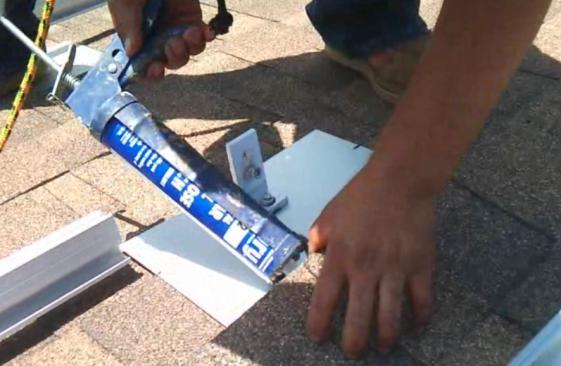
6 6mm metric Allen Key or 6mm hexagonal driver bit. Drill or impact driver for driving roof material fixings. Measuring tape Chalk Line Reel Glove Helmet


7 Orion Rail Rail Splice Kit Mid Clamp End Clamp Tile Hook for Spanish Tile Tile Hook for Flat Tile Tile Hook for Shingle Roof Ground Clip Ground Lug To determine bill of material for your project, Please log on Orion Racking Universal Calculator OrionRacking.com To find out how to install this system. Please click the link below Installation Procedure

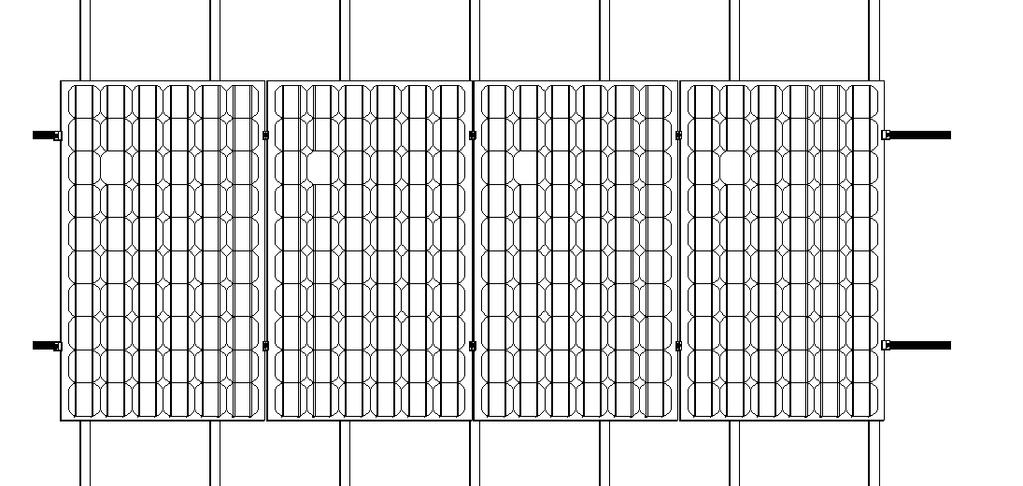
8 The solar panels must be located in the Roof Internal Zone. Placement of the array outside this zone will inflict undue stress on the framing fixings and clamps, and the warranty will be voided.
9
10
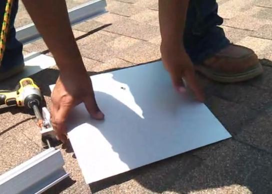
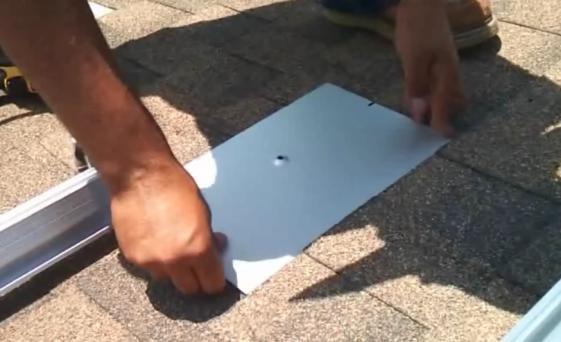
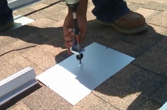
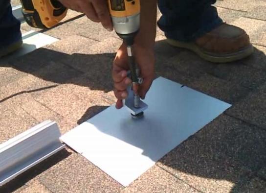
11
12
13
14
15
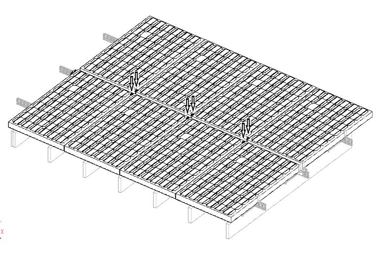
16 2 rows situation
17
18
19
20 To see detail installation animation please click the link below or Visit our website for actual installation photos
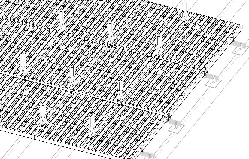
21 3 or more rows situation
22
23
24 To see detail installation animation please click the link below or Visit our website for actual installation photos
25
26

27 Rail calculations are based on code approved conventional mechanical section properties, material properties, stress equations, and allowable margins of safety. Beam calculations have been conservatively performed in non-snow areas with simply supported assumptions. Components have had full envelope forces from the tables applied to each component. This is prescriptive in nature and not a site specific engineering document for building permit application. Please contact Orion Racking Systems for more detailed information and for site specific engineering data on specific projects. ASCE 7-05 guidance for Wind is used in the tables. Rail Span Chart The following pages show engineering evaluations of the Orion Racking Flush-Mount System. Evaluations Include: Adjustable End Clamp Mid Clamp A270 Bolt Rail Foot Standard Rail Heavy Duty Rail L Foot Roof Bolt

28 Component: Adjustable End Clamp Allowable Load: 600lb Maximum Stress: 30ksi, OK Filenames Min Max Number Next Active Color Coordinate System Point Curve Surface Solid/ Valume Connector Region Connection Property Text Node Element Material Property Load Set Constraint Set View Group 1 Output Set Output Format 1 Workplane Origin X Y Z Workplane Normal X Y Z Workplane X Axis X Y Z Snap X Y Angle Model Extents X Y Z
29 Component: Mid Clamp Allowable Load: 600lb on a side Maximum Stress: 2.1ksi, OK Applied Tensile Force: N Mid Clamp Cantilever beam AB result N/mm2 moment (mm*n) I= bh-3/12 c Bending Stress Stress= M c/l psi psi result Shear Stress 3V/2A 1.26 N/mm psi
30 Component: A270 Bolt Allowable Load: 1200lb Tension 1200lb Shear Maximum Stress: 1.5ksi, OK Applied Tensile force : N Bolt bending Stress Stress= M c/l 0 N/mm2 result Moment (mm*n) I= bh-3/12 C 0 psi Result Shear Stress 3v/2A N/mm Component: Rail Foot Allowable Load: 1200lb Maximum Stress: 1ksi, OK psi Result P A=p i*r N/mm psi *A2-70 is a 304 stainless steel screw with a 700 N/mm2 tensile strength Foot Clamp cantilever beam BC Applied Tensile force : N result Moment (mm*n) I= bh- 3/12 C bending Stress Stress= M c/l 6.88 N/mm psi Result Shear Stress 3v/2A 4.82 N/mm psi *model as solid prismatic beam of length 1.5mm and height 4.2 mm
31 Component: Standard Rail See Span Charts for ratings Section Property Calculations Section Property Calculations Std base height area centroid height m base I (in^4) d ad^2 A b b c c d d e f f es bot g h ang i j k k l m h ave m v ave ^ centroid S in^3
32 Component: Heavy Duty Rail (See Span Charts for ratings) (0.5 added to interior void and thickened side wall) Add 0.5 to cut ine Section Property Calculations Section Property Calculations Added 0.5 In base height area centroid height m base I (in^4) d ad^2 A b b c c d d e f f es bot g h ang i j k k l m h ave m v ave ^ centroid S in^3
33 Rail Span Calculations Beam Calculations Parameters non-italics = calculated by internal software italics = location specific (engineering input) Beams L Trib Area LL w M Fb S req defl E I req R ft ft sf psf plf lb-ft psi in3 in psi in4 lb Simple Span hvy +.5 Standard Rail reg St h=20 w=85 t= E h=20 w=85 t= E h=20 w=85 t= E h=20 w=85 t= E h=20 w=85 t= E h=20 w=85 t= E h=30 w=85 t= E h=30 w=85 t= E h=30 w=85 t= E h=30 w=85 t= E h=30 w=85 t= E h=30 w=85 t= E h=40 w=85 t= E h=40 w=85 t= E h=40 w=85 t= E h=40 w=85 t= E h=40 w=85 t= E h=40 w=85 t= E h=30 w=90 t= E h=30 w=90 t= E h=30 w=90 t= E h=30 w=90 t= E h=30 w=90 t= E h=30 w=95 t= E h=30 w=95 t= E h=30 w=95 t= E h=30 w=95 t= E h=30 w=95 t= E h=30 w=100 t= E h=30 w=100 t= E h=30 w=100 t= E h=30 w=100 t= E h=30 w=100 t= E h=30 w=105 t= E h=30 w=105 t= E h=30 w=105 t= E h=30 w=105 t= E h=30 w=105 t= E h=30 w=110 t= E h=30 w=110 t= E h=30 w=110 t= E h=30 w=110 t= E h=30 w=110 t= E h=30 w=115 t= E h=30 w=115 t= E h=30 w=115 t= E h=30 w=115 t= E h=30 w=115 t= E h=30 w=120 t= E h=30 w=120 t= E h=30 w=120 t= E h=30 w=120 t= E h=30 w=120 t= E ,034 h=30 w=125 t= E h=30 w=125 t= E h=30 w=125 t= E h=30 w=125 t= E h=30 w=125 t= E
34 Rail Span Chart Rail Span Summary Height Wind Tilt Span ft mph degrees ft h=20 w=85 t= Standard Duty h=20 w=85 t= Standard Duty h=20 w=85 t= Standard Duty h=20 w=85 t= Standard Duty h=20 w=85 t= Heavy Duty h=20 w=85 t= Heavy Duty h=30 w=85 t= h=30 w=85 t= h=30 w=85 t= h=30 w=85 t= h=30 w=85 t= Heavy Duty h=30 w=85 t= Heavy Duty h=40 w=85 t= h=40 w=85 t= h=40 w=85 t= h=40 w=85 t= h=40 w=85 t= Heavy Duty h=40 w=85 t= Heavy Duty h=30 w=90 t= h=30 w=90 t= h=30 w=90 t= h=30 w=90 t= Heavy Duty h=30 w=90 t= Heavy Duty h=30 w=95 t= h=30 w=95 t= h=30 w=95 t= h=30 w=95 t= Heavy Duty h=30 w=95 t= Heavy Duty h=30 w=100 t= h=30 w=100 t= h=30 w=100 t= h=30 w=100 t= Heavy Duty h=30 w=100 t= Heavy Duty h=30 w=105 t= h=30 w=105 t= h=30 w=105 t= Heavy Duty h=30 w=105 t= Heavy Duty h=30 w=105 t= Heavy Duty h=30 w=110 t= h=30 w=110 t= h=30 w=110 t= Heavy Duty h=30 w=110 t= Heavy Duty h=30 w=110 t= Heavy Duty h=30 w=115 t= h=30 w=115 t= h=30 w=115 t= Heavy Duty h=30 w=115 t= Heavy Duty h=30 w=115 t= Heavy Duty h=30 w=120 t= h=30 w=120 t= h=30 w=120 t= Heavy Duty h=30 w=120 t= Heavy Duty h=30 w=120 t= Heavy Duty h=30 w=125 t= h=30 w=125 t= h=30 w=125 t= Heavy Duty h=30 w=125 t= Heavy Duty h=30 w=125 t= Heavy Duty
35 Component: L Foot Allowable Load: Maximum Stress: 2200lb Reaction 7.8ksi, OK L Foot Cantilever beam EF Applied Tensile force : N 500 Moment (mm*n) I= bh-3/12 C result bending Stress Stress= M c/l N/mm Component: Roof Bolt Allowable Load: Maximum Stress: L Foot Cantilever beam EF 2200lb Reaction 7.8ksi, OK Applied Tensile force : N 500 Result Moment (mm*n) I= bh-3/12 C Shear Stress 3v/2A 19.5 N/mm psi Result Axial Stress P/A 13 N/mm /8 lag, 4" into roof Graming member psi
36 warrants that its Solar Panel Mounting System (Frame) is free from defects in materials and workmanship for a period of 17 years from the date on which the Frame is purchased from Orion Solar Racking (Warranty Period), on the terms set out in this warranty. In the event that the Frame does not conform to this warranty during the Warranty Period, will, at its option, either repair or replace the Frame or pay the cost of having the Frame repaired or replaced. To the extent permitted by law, s total liability under this warranty will in no circumstances exceed the repair or replacement of the Frame or payment of the cost of having the Frame repaired or replaced. In the event of replacement of the Frame, any remaining part of the Warranty Period will be transferred to the replacement Frame. This warranty will not apply to any defect or damage to the Frame arising directly or indirectly from: A. shipment or storage of the Frame; B. improper installation, maintenance, repair or use of the Frame; C. normal wear and tear; D. misuse, neglect, abuse, accidental damage or modification to the Frame; E. failure to observe the instructions set out in the System Manual; or F. power failure, power surges, lightning, fire, explosion, flood, extreme weather conditions, environmental disasters or other causes outside s control, as determined by in its sole discretion. This warranty does not cover, and under no circumstances will be liable for, any costs associated with the removal, shipping, handling or re-installation of the Frame or the costs of sending personnel to any site to repair or replace the Frame. This warranty is only provided to the original purchaser of the Frame from (Purchaser) or, where the Purchaser is an installer or builder who on-supplies the Frame to another party, to that other party (End-User). This warranty is not transferable. Where an End-User wants make a claim under this warranty, the End-User must in the first instance contact the installer or builder from whom the Frame was purchased. All warranty claims must be: made in writing and addressed to the Customer Service Office: : 2917 Vail Ave., Commerce, CA 90040; and accompanied by proof of purchase of the Frame in a form acceptable to. This warranty will not apply to any claims received by after the expiration of the Warranty Period. makes no warranties, express or implied, other than the warranties made herein, and specifically disclaims all other warranties, representations and conditions to the extent permitted by law. To the extent permitted by law, in no circumstances will be liable for direct, indirect, special or consequential damages arising from a defective Frame or for any damage or injury to persons or property. s aggregate liability, if any, in damages or otherwise, will not exceed the invoice value of the Frame at the time of purchase from. Any provision contained in this warranty which is prohibited or unenforceable in any jurisdiction will be deemed to be ineffective to the extent of such prohibition or unenforceability and will not invalidate the remaining provisions nor affect the validity or enforceability of that provision in any other jurisdiction. This warranty will be governed and construed in accordance with the laws of the State of California and the parties irrevocably submit to the exclusive jurisdiction of the State of California.
XIAMEN FENGWEI ENERGY TECHNOLOGY CO., LTD. GRACE SOLAR ROOF MOUNTING SYSTEM INSTALLATION Manual
 XIAMEN FENGWEI ENERGY TECHNOLOGY CO., LTD. GRACE SOLAR ROOF MOUNTING SYSTEM INSTALLATION Manual Contents Chapter Title Page 1 General information 3 2 Safety and Installer Responsibilities 4 3 Technical
SOLAR ROOF MOUNTING SYSTEM INSTALLATION MANUAL Model Name TT-ADJUSTABLE TILT LEGS
 SOLAR ROOF MOUNTING SYSTEM INSTALLATION MANUAL Model Name TT-ADJUSTABLE TILT LEGS JIANGYIN TITANERGY CO.,LTD Contents Chapter Title Page 1 General Information 3 2 Safety and Installer Responsibilities
Unirac Installation Manual
 Tile Roof Hook Universal Mount Unirac R Pub 090727-1ii June 2009 A HILTI GROUP COMPANY Unirac welcomes input concerning the accuracy and user-friendliness of this publication. Please write to publications@unirac.com.
orientation Conergy SunTop Instructions for professional installation
 On-roof Framed modules Portrait orientation Landscape Three-tab Shingle Plain tile Slate Double Roman tile Metal roof Material warranty orientation Conergy SunTop Instructions for professional installation
Installation Manual XRL Solar Rail System
 Installation Manual XRL Solar Rail System Solar Mounting Solutions June 2009 www.ironridge.com 2009 IronRidge, Inc. All Rights Reserved Version 1.0 2 XRL Solar Rail System Installation Guide Introduction
SolarMount-I INSTALLATION MANUAL
 SolarMount-I INSTALLATION MANUAL 2010 by Unirac, Inc. All rights reserved. Pub 100621-1ii, June 2010 R A HILTI GROUP COMPANY 1411 Broadway Boulevard NE Albuquerque, NM 87102-1545 USA IMPORTANT! Unirac
SolarMount (E)volution
volution") SolarMount (E)volution SOLARMOUNT (E)VOLUTION: THE BEST JUST GOT BETTER. Engineering, Excellence, and Ease. Performance Engineered for versatility and reduced installation time, SolarMount (E)volution
SolarMount (E)volution SOLARMOUNT (E)VOLUTION: THE BEST JUST GOT BETTER. Engineering, Excellence, and Ease. Performance Engineered for versatility and reduced installation time, SolarMount (E)volution
ROOF MOUNT. *Class A* Fire Rated INSTALLATION MANUAL
 ROOF MOUNT 4008083 *Class A* Fire Rated INSTALLATION MANUAL Contents DISCLAIMER 1 RATINGS 1 CHECKLIST 2 PRIMARY COMPONENTS 3 1. ATTACH BASES 3 2. PLACE RAILS 3 3. SECURE LUG 4 4. CLAMP MODULES 4 EXPANSION
AM95 Installation Guide
 1321 S. State College Blvd., Fullerton, CA 92831 USA Included Components: Maximum Flat Panel Weight: 95 lb. / 43.1 kg. M4 X 25mm M5 X 25mm M6 X 12mm (Qty 2) M6 X 25mm M8 X 25mm Allen Key Plastic Cover
ROOF MOUNT. *Class A* Fire Rated INSTALLATION MANUAL
 ROOF MOUNT 4008083 *Class A* Fire Rated INSTALLATION MANUAL CONTENTS DISCLAIMER 1 RATINGS 1 CHECKLIST 2 PRIMARY COMPONENTS 3 0. ATTACH BASES 3 1. PLACE RAILS 3 2. SECURE LUG 4 3. CLAMP MODULES 4 EXPANSION
Unirac Flat Flashing INSTALLATION MANUAL
 Unirac Flat Flashing INSTALLATION MANUAL 2011 by Unirac, Inc. All rights reserved. Pub 110301-1ii, March 2011 A HILTI GROUP COMPANY R 1411 Broadway Boulevard NE Albuquerque, NM 87102-1545 USA IMPORTANT!
Comfort 10S Wall Hardwire Installation and Operations Manual
 Comfort 10S Wall Hardwire Installation and Operations Manual 10/24/2012 REQUIRED TOOLS STARHEAD SCREWDRIVERS DRILL & BIT FLAT HEAD SCREWDRIVERS ALLEN KEY PENCIL MEASURING TAPE LEVEL ELECTRICAL REQUIREMENTS:
Chiko Flat Pitched roof installation roof installation Guide Gui
 Mounting Systems Tilt Kit Installation Guide Table of Contents Part I. Preparing.. 2-6 Part II. Feature of the Rail and the Module 6-8 Part III. Planning the array laylout... 9 Part IV. Installation instruction.
MRac Solar Carport System Installation Guide
 MRac Solar Carport System Installation Guide Content 1 Product Introduction ------------------------------------------P2 2 Installation Tool & Components-------------------------------P3 3 Installation
Owner s Manual & Safety Instructions
 Owner s Manual & Safety Instructions Save This Manual Keep this manual for the safety warnings and precautions, assembly, operating, inspection, maintenance and cleaning procedures. Write the product s
Installation Manual. Tamarack Solar Products. Top of Pole Mount Edition v1.01. For models:
 Mount Installation Manual 2016 Edition v1.01 For models: UNI-TP/06 UNI-TP/06LL UNI-TP/08 UNI-TP/08LL UNI-TP/10 UNI-TP/10LL UNI-TP/12 UNI-TP/12LL UNI-TP02-MAN Table of Contents 1 Introduction 1 2 Customer
Single Flex and Double Flex Couplings (i)
") Single Flex and Double Flex Couplings (i) FORM NO. L00G00 In accordance with Nexen s established policy of constant product improvement, the specifications contained in this manual are subject to change
Single Flex and Double Flex Couplings (i) FORM NO. L00G00 In accordance with Nexen s established policy of constant product improvement, the specifications contained in this manual are subject to change
Single Arm Pole Mount. Installation Manual Edition v1.01. For models: UNI-SA/14 UNI-SA/21.5 UNI-SA/26 UNI-SA01-MAN
 Pole Mount Installation Manual 2016 Edition v1.01 For models: UNI-SA/14 UNI-SA/21.5 UNI-SA/26 UNI-SA01-MAN Table of Contents 1 1 2 3 4 5 5 Introduction Customer Support Project Essentials Assembly: Steps
Mounting Systems. Tilt Kit Installation Guide. Tilt Kit Installation Guide. Table of Contents
 Mounting Systems Tilt Kit Installation Guide Tilt Kit Installation Guide Table of Contents Part I. Preparing.........................................2-4 Part II. Feature of the Rail and the Module...................
FXL-168 FIXED RACK ASSEMBLY INSTRUCTIONS SALES ORDER #
 ZOMEWORKS FXL-168 FIXED RACK ASSEMBLY INSTRUCTIONS SALES ORDER # 1 1011 Sawmill Road NW, PO Box 25805, Albuquerque, NM 87125 USA (505) 242-5354 / (800) 279-6342 / FAX (505) 243-5187 E-mail: zomework@zomeworks.com
VAN STORAGE SOLUTIONS FOR THE WAY YOU WORK
 WWW.WEATHERGUARD.COM VAN STORAGE SOLUTIONS FOR THE WAY YOU WORK Weather Guard / KNAACK 420 E. Terra Cotta Ave. Crystal Lake, IL 60014 USA 800-456-7865 (Toll Free) 800-334-2981 (Fax) Knaack.OrderEntry@wernerco,.com
MRac Ground Terrace VI Installation Guide (with Ground Screw)
") MRac Ground Terrace VI Installation Guide (with Ground Screw) Content 1 Product Introduction--------------------------------------------------------------------P2 2 Installation Tools & Components-----------------------------------------------------P3
MRac Ground Terrace VI Installation Guide (with Ground Screw) Content 1 Product Introduction--------------------------------------------------------------------P2 2 Installation Tools & Components-----------------------------------------------------P3
P4263TP. Installation Guide. Low-Profile Tilting Portrait Mount for Flat-Panels
 Low-Profile Tilting Portrait Mount for Flat-Panels 1321 S. State College Blvd., Fullerton, CA 92831 USA Weight Limit Maximum Flat Panel Weight: 175 lbs. Warning Statements THE WALL STRUCTURE MUST BE CAPABLE
PV-ezRack Solar Terrace II-A Installation guide
 PV-ezRack Solar Terrace II-A Installation guide Contents 1 Introduction..2 2 Tools & Components.3 3 System overview.4 4 Installation steps..7 5 Notices and Safety Precautions.. 14 6 Project Case...16 7
SunPower Installation Manual
 SunPower SF System Planning and Assembly SunPower SUNPOWER CORPORATION WWW.SUNPOWERCORP.COM Pub #101001-SP2 October 2010 - Rev. 8 2010 by SunPower, Corp All rights reserved. Part I. Scope, components,
ATTENTION: PLEASE READ AND UNDERSTAND ALL INSTRUCTIONS AND WARNINGS BEFORE ASSEMBLING, INSTALLING OR USING THIS PRODUCT.
 PLAN YOUR VAN (TIPS FOR FASTER INSTALLATION) Installing your Transit bulkhead is very clear cut following these instructions. Before cutting or drilling in the floor, verify the location of you gas tank,
INSTALLATION INSTRUCTIONS
 CREATING POSITIVE CUSTOMER EXPERIENCES INSTALLATION INSTRUCTIONS Universal Low Profile Tilt Mount for 42 to 63 Flat Panels NORTH AMERICA 3130 East Miraloma Avenue Anaheim, CA 92806 USA USA and Canada Phone:
Sonoma Outdoor Kitchen Pergola. Assembly Instructions
 Sonoma Outdoor Kitchen Pergola Assembly Instructions Introduction Thank you for your purchase from The Outdoor GreatRoom Company. This pergola has been engineered and manufactured in the USA. This user
Structural Criteria for Residential Flush-Mounted Solar Arrays
 Structural Criteria for Residential Flush-Mounted Solar Arrays Planning and Development Building & Safety Division 1. ROOF CHECKS A. Visual Review/Contractor s Site Audit of Existing Conditions: 1) Is
PRC-LA Installation Guide
 1321 S. State College Blvd., Fullerton, CA 92831 USA Weight Limit Maximum Flat Panel Weight: Warning Statements 50 lbs. THE WALL STRUCTURE MUST BE CAPABLE OF SUPPORTING AT LEAST FOUR TIMES THE WEIGHT OF
Butterfly Hinge Standard & Heavy Duty PLEASE READ OWNER'S MANUAL COMPLETELY BEFORE INSTALLING YOUR HINGE KIT.
 Butterfly Hinge Standard & Heavy Duty Installation Instructions PLEASE READ OWNER'S MANUAL COMPLETELY BEFORE INSTALLING YOUR HINGE KIT. For use with Vinyl, Aluminum and Wood. Heavy Duty Butterfly Hinge
Installation Instructions
 Articulating Hex Monitor Mount Stand Installation Instructions UNPACKING Carefully open the carton, remove contents, and place them on a protected surface to avoid damage. Check the parts and the Supplied
MANUAL METAL SHRINKER/STRETCHER
 MANUAL METAL SHRINKER/STRETCHER Model 95062 ASSEMBLY AND OPERATING INSTRUCTIONS Due to continuing improvements, actual product may differ slightly from the product described herein. 3491 Mission Oaks Blvd.,
INSTALLATION INSTRUCTIONS
 INSTALLATION INSTRUCTIONS CTM-MS1 Flat Panel Display Mount (26 to 37 ) NORTH AMERICA 3130 East Miraloma Avenue Anaheim, CA 92806 USA USA and Canada Phone: 800-368-9700 Fax: 800-832-4888 Other Locations
INSTALLATION GUIDE SM SOLAR MOUNT PUB15JAN01
 MOUNT INSTALLATION GUIDE PUB5JAN0 SM SOLAR Wrenches and Torque Wrench Size Recommended Torque (ft-lbs) /4 Hardware 7/6 *0 3/8 Hardware 9/6 *30 # Hardware 5/6 0 Torques are not designed for use with wood
MDU-C-SERIES STORAGE RACKS INSTRUCTION MANUAL
 VESTIL MANUFACTURING CP. 2999 North Wayne Street, P.O. Box 507, Angola, IN 46703 Telephone: (260) 665-7586 -or- Toll Free (800) 348-0868 Fax: (260) 665-1339 www.vestilmfg.com e-mail: sales@vestil.com MDU-C-SERIES
Installation Manual Tilt Leg
 Installation Manual Tilt Leg Solar Mounting Solutions March www.ironridge.com 2010 IronRidge, Inc. All Rights Reserved Version 2.0 2 Tilt Leg Installation Guide Introduction The Tilt Leg is a flexible
9 PIECE TUNGSTEN CARBIDE HOLE SAW KIT. Model 90721
 9 PIECE TUNGSTEN CARBIDE HOLE SAW KIT Model 90721 Set up And Operating Instructions Diagrams within this manual may not be drawn proportionally. Due to continuing improvements, actual product may differ
Shrinker and stretcher
 Shrinker and stretcher Model 96465 Assembly And Operation Instructions Due to continuing improvements, actual product may differ slightly from the product described herein 3491 Mission Oaks Blvd, Camarillo,
INSTALLATION MANUAL v. 1.0
 INSTALLATION MANUAL v. 1.0 2009 by Unirac, Inc. All rights reserved. Pub 090501-1ii, May 2009 www.clicksys-beam.com IMPORTANT! Unirac Inc. makes no warranty of any kind with regard to this material, including,
YGR-LO-8 GUARD RAILING YGR-TP18 & YGR-TP42 POSTS Installation Manual
 VESTIL MANUFACTURING CORP. 2999 North Wayne Street, P.O. Box 507, Angola, IN 46703 Telephone: (260) 665-7586 -or- Toll Free (800) 348-0868 Fax: (260) 665-1339 www.vestilmfg.com e-mail: sales@vestil.com
1300-lb Furniture and Crate Movers
 1300-lb Furniture and Crate Movers Owner s Manual WARNING: Read carefully and understand all ASSEMBLY AND OPERATION INSTRUCTIONS before operating. Failure to follow the safety rules and other basic safety
ECM Installation Guide Installationsanleitung, Guía de Instalacíon, Guida de Installazione, Guide d Installation, Installatie gids
 Elliptical Ceiling Mount for 37 to 63 Flat Panels Model: ECM-3000 Warranty, Garantie, Garantía, Garanzia, Garantie, Waarborg: http://www.mounts.com/warranty 9531-000-001-0X Rev.0 www.mounts.com North America
Tilting & Swiveling Flat Panel Wall Mount Installation Guide Model: AXS2040
 Tilting & Swiveling Flat Panel Wall Mount Installation Guide Model: AXS2040 20-40 66 lbs. Supports VESA sizes up to: 200x200 For technical assistance or troubleshooting please call 1-855-994-2825 or visit
AM500-U Installation Guide
 1321 S. State College Blvd., Fullerton, CA 92831 USA Included Components Maximum Flat Panel Weight: 500 lb. / 226.79 kg. Wall Mount Bracket (Qty 2) Cross Bar 5/16 Flat Washers (Qty 6) Universal Spacers
RFTX-1 Installation Manual
 RFTX-1 Installation Manual complete control Universal Remote Control RFTX-1 Installation Manual 2009-2014 Universal Remote Control, Inc. The information in this Owner s Manual is copyright protected. No
PV System Structural Criteria
 PV System Structural Criteria Town of Atherton Building Department 91 Ashfield Road Atherton, California 94027 Phone: (650) 752-0560 STRUCTURAL CRITERIA FOR RESIDENTIAL ROOFTOP FLUSH-MOUNTED SOLAR ARRAYS
SolarMount-I INSTALLATION MANUAL Broadway Boulevard NE Albuquerque, NM USA A HILTI GROUP COMPANY
 SolarMount-I INSTALLATION MANUAL 2011 by Unirac, Inc. All rights reserved. Pub 110518-1ii, May 2011 A HILTI GROUP COMPANY R 1411 Broadway Boulevard NE Albuquerque, NM 87102-1545 USA IMPORTANT! Unirac Inc.
INSTALLATION INSTRUCTIONS
 INSTALLATION INSTRUCTIONS Premier Mounts Tilting Wall Mount Model: TWM-085 For use with Panasonic 85 Flat Panel NORTH AMERICA 3130 East Miraloma Avenue Anaheim, CA 92806 USA USA and Canada Phone: 1.800.368.9700
Installation Manual. Side of Pole Mount Edition v1.02. For models:
 Side of Pole Mount Installation Manual 2015 Edition v1.02 For models: UNI-SP/01 UNI-SP/01A UNI-SP/01XH UNI-SP/01XX UNI-SP/02 UNI-SP/02A UNI-SP/02X UNI-SP/03 UNI-SP01-MAN Installation Manual Side of Pole
QuadroMAX. Installation Manual. QM Series. LED Outdoor Lighting Fixtures REV: 3/22/16
 QuadroMAX LED Outdoor Lighting Fixtures Installation Manual QM Series REV: 3/22/16 BEFORE YOU BEGIN Read these instructions completely and carefully. WARNING Risk of fire or electric shock. Luminaire wiring
Installation Manual. Tamarack Solar Products. Side of Pole Mount Edition v1.02. For models:
 Mount Installation Manual 2016 Edition v1.02 For models: UNI-SP/01 UNI-SP/01A UNI-SP/01XH UNI-SP/01XX UNI-SP/02 UNI-SP/02A UNI-SP/02X UNI-SP/03 UNI-SP01-MAN Table of Contents 1 Introduction 1 Customer
30 Bending Brake. Model Assembly and Operating Instructions. Distributed exclusively by Harbor Freight Tools.
 30 Bending Brake Model 41311 Assembly and Operating Instructions Distributed exclusively by Harbor Freight Tools. 3491 Mission Oaks Blvd., Camarillo, CA 93011 Copyright 1999 by Harbor Freight Tools. All
Heavy Duty Contemporary Hinge Kit PLEASE READ OWNER'S MANUAL COMPLETELY BEFORE INSTALLING.
 Heavy Duty Contemporary Hinge Kit Installation Instructions PLEASE READ OWNER'S MANUAL COMPLETELY BEFORE INSTALLING. For use with Wood and Vinyl Gates Supports Gates up to 150lbs. and 96" wide. 5007EPN
Structural Criteria for Residential Rooftop Solar Energy Installations
 DOCUMENT #5 Structural Criteria for Residential Rooftop Solar Energy Installations STRUCTURAL CRITERIA FOR RESIDENTIAL FLUSH-MOUNTED SOLAR ARRAYS 1. ROOF CHECKS A. Visual Review/Contractor s Site Audit
Unirac Installation Manual
 Tile Roof Hook Universal Mount Unirac R Pub 120803-1ii August 2012 A HILTI GROUP COMPANY Unirac welcomes input concerning the accuracy and user-friendliness of this publication. Please write to publications@unirac.com.
Mortising Attachment
 Mortising Attachment Owner s Manual WARNING: Read carefully and understand all ASSEMBLY AND OPERATION INSTRUCTIONS before operating. Failure to follow the safety rules and other basic safety precautions
INSTALLATION INSTRUCTIONS
 INSTALLATION INSTRUCTIONS P4263F Universal Low Profi le Flat Mount for 42 to 63 Flat Panels NORTH AMERICA 3130 East Miraloma Avenue Anaheim, CA 92806 USA USA and Canada Phone: 1.800.368.9700 Fax: 1.800.832.4888
PV-ezRack PostMount 1-A Installation Guide
 PV-ezRack PostMount 1-A Installation Guide NO.: PZ10A -IM06-10 Version:V1.0 Editor: Edit date: Check by: Audit by: Approve by: File record Content Editor Date V1.0 English Bronze 2015.4.17 CONTENT 1. Introduction..
INSTALLATION GUIDE SM SOLAR MOUNT PUB15JUN15
 MOUNT INSTALLATION GUIDE PUB5JUN5 Wrenches and Torque SM SOLAR Wrench Size Recommended Torque (ft-lbs) /4 Hardware 7/6 *0 3/8 Hardware 9/6 *30 # Hardware 5/6 0 Torques are not designed for use with wood
Ready-To-Assemble VersaRail INSTALLATION INSTRUCTIONS
 Ready-To-Assemble VersaRail INSTALLATION INSTRUCTIONS Read all instructions prior to installing product. Refer to manufacturers safety instructions when operating any tools. To register your product, please
One Shelf, Wall Mounted A/V Component Stand Installation Guide Model: EX101SS
 One Shelf, Wall Mounted A/V Component Stand Installation Guide Model: EX0SS For technical assistance or troubleshooting please call -855-994-3832. This product is intended for use only with Audio/Video
Tilting, Swiveling & Rotating Flat Panel Wall Mount
 Tilting, Swiveling & Rotating Flat Panel Wall Mount Model: VXA980TC +5 to -5 +5 to -5 Supports most 0-80 Flat Panel TVs Maximum Weight Capacity: 32 lbs. Supports VESA Sizes up to 600x500 For technical
The MFJ-1754 can be mounted on any 1" to 1 1/2" mast (conductive or non conductive.)
") INTRODUCTION: The MFJ-1754 is designed for use on the 2 meter and the 70 centimeter bands. On the 2 meter band the MFJ-1754 behaves as a vertical 1/4 wave antenna, however on 70 centimeter band the MFJ-1754
INTRODUCTION: The MFJ-1754 is designed for use on the 2 meter and the 70 centimeter bands. On the 2 meter band the MFJ-1754 behaves as a vertical 1/4 wave antenna, however on 70 centimeter band the MFJ-1754
Vista SCREEN. and Double Door Link Kit. Installation Manual for. For Double Doors (French Doors) Quick and Easy to Size and Install
 Quick and Easy to Size and Install") and Double Door Link Kit Installation Manual for Vista SCREEN TM Quick and Easy to Size and Install For Double Doors (French Doors) Durable. Reliable. Attractive. For door openings up to 72 13 /16 (1,849
and Double Door Link Kit Installation Manual for Vista SCREEN TM Quick and Easy to Size and Install For Double Doors (French Doors) Durable. Reliable. Attractive. For door openings up to 72 13 /16 (1,849
Page 1 of 18. SunRail System Installation Instructions
 Page 1 of 18 SunRail System Installation Instructions Page 2 of 18 SunRail Stainless Steel Railing Installation Guide Table of Contents Before You Begin 3 Installing Surface Mount Bases for a Two Rail
Installation Manual. Side of Pole Mount Edition v3.24. For models:
 Mount Installation Manual 2016 Edition v3.24 For models: UNI-SP/01 UNI-SP/01A UNI-SP/01XH UNI-SP/01XX UNI-SP/02 UNI-SP/02A UNI-SP/02X UNI-SP/03 UNI-SP/03W UNI-SP01-MAN Table of Contents 1 1 2 3 4 5 6 7
FIXED-POSITION WALL MOUNT FOR TVs in.
 INSTALLATION GUIDE FIXED-POSITION WALL MOUNT FOR TVs 19-39 in. NS-HTVMFAB For wood-stud, solid concrete wall, or concrete block installations Safety information and specifications..... 2 Tools needed.............................
By SP Partners, LLC. INSTALLATION GUIDE. ProTech
 By SP Partners, LLC www.rainbowatticstair.com INSTALLATION GUIDE ProTech By SP Partners, LLC www.rainbowatticstair.com INSTALLATION GUIDE ProTech IMPORTANT - READ THIS FIRST Inspect stair for any damage
10 Ton Pull Back Ram
 10 Ton Pull Back Ram Model 97207 Set up And Operating Instructions Diagrams within this manual may not be drawn proportionally. Due to continuing improvements, actual product may differ slightly from the
Tilting Flat Panel Wall Mount Installation Guide
 Tilting Flat Panel Wall Mount Installation Guide Model: A580TM Easy installation Built-in level for easy positioning Safety bolts lock the TV on the mount Easy to adjust tilt angles: +5 to -15 degrees
WallAccess - No Door
 By SP Partners, LLC www.rainbowatticstair.com INSTALLATION GUIDE WallAccess - No Door June 2012 IMPORTANT READ THIS FIRST Inspect stair for any damage prior to installation. Stair is NOT to be installed
EzQuikTM. MicroSolar System EzQuik TM Aluminum Solar PV Module Mounting System. Code-Compliant Installation Manual V1011 (AS/NZ1170) Model 2012
 Model 2012") TM Model 2012 Code-Compliant Installation Manual V1011 (AS/NZ1170) MicroSolar System TM Aluminum Solar PV Module Mounting System 1 CONTENTS SECTION 1 INTRODUCTION... 3 1.1... 3 1.2 Why?... 3 1.3 Before
TM Model 2012 Code-Compliant Installation Manual V1011 (AS/NZ1170) MicroSolar System TM Aluminum Solar PV Module Mounting System 1 CONTENTS SECTION 1 INTRODUCTION... 3 1.1... 3 1.2 Why?... 3 1.3 Before
Dual Arm Tilt LCD Mount
 Installation Manual model # 51324 M o u n t i n g S y s t e m s Dual Arm Tilt LCD Mount Fits Displays 13 to 32 Supports Up to 50 lbs (23 kgs) Projection from Wall from 3 to 17 Meets VESA Standards 50/75/100,
ADJUSTABLE MOUNTING POST
 C Part Number 069 B EACH CARTON CONTAINS D Floor Mounting Kit A. Bottom Post Assembly B. Top Post Assembly C. Flange Head Bolts (x2) D. Floor Mounting Kit. 5/8 Wx/6 Hx0 L framing channels (x2) 2. /8-6x4
PATRIOT DOCKS ASSEMBLY INSTRUCTIONS
 6/1/2008 PATRIOT DOCKS ASSEMBLY INSTRUCTIONS Congratulations on your new Patriot Dock purchase. This manual contains instructions to assemble basic dock configurations for use at typical shoreline application.
INSTALLATION INSTRUCTIONS
 INSTALLATION INSTRUCTIONS Universal Swingout Arm for 37 to 47 Flat Panels Model: AM80 NORTH AMERICA 3130 East Miraloma Avenue Anaheim, CA 92806 USA USA and Canada Phone: 1-800-368-9700 Fax: 1-800-832-4888
GB-AVSTOR5 Ceiling Equipment Storage Box with Pipe Coupler
 Ceiling Equipment Storage Box with Pipe Coupler INSTALLATION INSTRUCTIONS CREATING POSITIVE CUSTOMER EXPERIENCES 9534-500-021-00 Contents Weight Limit... 2 Warning Statements... 2 Installation Tools...
SHRINKER/STRETCHER SET Create radius bends and contours in sheet metal
 Owner s Manual & Safety Instructions Save This Manual Keep this manual for the safety warnings and precautions, assembly, operating, inspection, maintenance and cleaning procedures. Write the product s
Flush Mount. SunEarth Flush Mount Installation Manual. SunEarth Flush Mount. Asphalt Shingle Roofing
 Flush Mount SunEarth Flush Mount Installation Manual Thank you for choosing the SunEarth flush mount method. It provides a strong durable solution for mounting SunEarth collectors parallel to the roof
Assembly Instructions
 Thank You For Purchasing The Best Overhead Storage Rack Assembly Instructions Overhead Storage Rack 8 x 4 8 x 3 8 x 2 6 x 4 6 x 3 6 x 2 4 x 4 Two 8 x4 Racks Pictured P.O. Box 714, El Cerrito, CA 94530
Gypsy Statement of Limited Warranty. Part 1 General Terms
 Gypsy Statement of Limited Warranty Part 1 General Terms This Statement of Limited Warranty includes Part 1 General Terms, and Part2 Warranty Information. The warranties provided by PROVO CRAFT AND NOVELTY,
Specifications. Important Safety Information
 Specifications Tire Rim Capacity 4 to 12 Rim Height 16 (2) Bead Breaker Handles 21 Long Includes Aluminum Centering Cone (2) Nylon Spacers Important Safety Information 1. Do not exceed max. tire capacity.
Lodge II Pergola. Manual and Installation Instructions. Please read these instructions before removing parts from crate
 Lodge II Pergola Manual and Installation Instructions Please read these instructions before removing parts from crate Introduction Thank you for your purchase from The Outdoor GreatRoom Company. This pergola
INSTALLATION MANUAL SONANCE SOUNDBARS SB46 M AND SB46 L. Introduction. Box Contents. Wall Mount Installations
 INSTALLATION MANUAL SONANCE SOUNDBARS SB46 M AND SB46 L Introduction Thank you for purchasing the Sonance Soundbar SB46 M or SB46 L. When properly installed your new Soundbar will give you years of entertainment
SILVERBACK INSTALLATION MANUAL
 SILVERBACK INSTALLATION MANUAL R-SERIES SOLAR RACKS T OLL FREE 866-766-3727 WWW.ROOFSCREEN.COM Introduction... 2 The Silverback Solar Racking System... 2 This manual... 2 Application... 2 System Overview...
ATTENTION: PLEASE READ AND UNDERSTAND ALL INSTRUCTIONS AND WARNINGS BEFORE ASSEMBLING, INSTALLING OR USING THIS PRODUCT.
 INSTALLATION MANUAL Models 96111-3-02 & 96511-3-02 Bulkheads for 2014 and Later Ford Transit Connect Vans ATTENTION: PLEASE READ AND UNDERSTAND ALL INSTRUCTIONS AND WARNINGS BEFORE ASSEMBLING, INSTALLING
Line 6 L I M I T E D R E F URBISH E D (B-ST O C K) W A RR ANT Y
 W A RR ANT Y") Line 6 L I M I T E D W A RR A N T Y PO L I C Y PLEASE READ THIS DOCUMENT CAREFULLY. IT CONTAINS IMPORTANT INFORMATION ABOUT YOUR RIGHTS AND OBLIGATIONS, AS WELL AS LIMITATIONS AND EXCLUSIONS THAT MAY APPLY
Line 6 L I M I T E D W A RR A N T Y PO L I C Y PLEASE READ THIS DOCUMENT CAREFULLY. IT CONTAINS IMPORTANT INFORMATION ABOUT YOUR RIGHTS AND OBLIGATIONS, AS WELL AS LIMITATIONS AND EXCLUSIONS THAT MAY APPLY
HOME BAR SERIES 3 DRAWER BASE
 HOME BAR SERIES 3 DRAWER BASE Warning: Excessive weight hazard! Use two or more people to move, assemble or install wine cabinets to avoid back injury. Do not leave children unattended near cabinets. High
DOOR SECURITY AND REPAIR KIT
 DOOR SECURITY AND REPAIR KIT MODEL #S SET-SLP-X0552 SET-STD-X0552 SET-UNI-X0002 SET-ULT-X0002 R Questions? Call customer service at -888-582-2294 or visit www.armorconcepts.com PACKAGE CONTENTS A B C E
INSTRUCTION BOOK FOR. IDEA Screen & Panoramic for Nureva Span
 INSTRUCTION BOOK FOR IDEA Screen & Panoramic for Nureva Span Disclaimer Milestone and its affiliated corporations and subsidiaries (collectively "Milestone"), intend to make this manual accurate and complete.
INSTALLATION INSTRUCTIONS
 INSTALLATION INSTRUCTIONS Universal Swingout Arm Model: AM300/AM300-B NORTH AMERICA 3130 East Miraloma Avenue Anaheim, CA 92806 USA USA and Canada Phone: 1.800.368.9700 Fax: 1.800.832.4888 Other Locations
14 Piece Slide Hammer and Puller Set
 Owner s Manual & Safety Instructions Save This This Manual Keep Keep this this manual manual for for the the safety safety warnings warnings and and precautions, assembly, assembly, operating, inspection,
Instruction Sheet REB SERIES. Rotating Sliding Base REB18
 Instruction Sheet REB SERIES Rotating Sliding Base REB14 REB18 THANK YOU Thank you for purchasing the REB Series Rotating Sliding Base. Please read these instructions thoroughly before installing this
Owner s Manual Mobile Flat-Panel Floor Stand
 Owner s Manual Mobile Flat-Panel Floor Stand Model: DMCS3270XP Espanol 13 Francais 25 Русский 37 Deutsch 49 CAUTION: DO NOT EXCEED MAXIMUM LISTED WEIGHT CAPACIT. SERIOUS INJUR OR PROPERT DAMAGE MA OCCUR!
Code-Compliant Planning and Installation Complying with AS/NZS1170.2:2011 ADMT
 PV-ezRack SolarRoof Code-Compliant Planning and Installation Complying with AS/NZS1170.2:2011 ADMT 2-2012 CONTENT 1. Introduction 2 2. Planning. 3 3. Component List 9 4. Array planning.. 10 5. Step by
Structural Criteria for Residential Rooftop Solar Energy Installations
 TOOLKIT DOCUMENT #5 Structural Criteria for Residential Rooftop Solar Energy Installations CRITERIA FOR RESIDENTIAL FLUSH-MOUNTED SOLAR ARRAYS STRUCTURAL 1. ROOF CHECKS A. Visual Review/Contractor s Site
Heavy-Duty Gate Latch (Self-Latching)
") Heavy-Duty Gate Latch (Self-Latching) Installation Instructions PLEASE READ OWNER'S MANUAL COMPLETELY BEFORE INSTALLING YOUR HINGE KIT. 5010EPN V1 4/14 Owner's Manual Version 1.0 For use with; aluminum
Heavy-Duty Gate Latch (Self-Latching) Installation Instructions PLEASE READ OWNER'S MANUAL COMPLETELY BEFORE INSTALLING YOUR HINGE KIT. 5010EPN V1 4/14 Owner's Manual Version 1.0 For use with; aluminum
SNAP-FAN INSTALLATION
 ! SNAP-FAN INSTALLATION Only a qualified and licensed electrician or contractor should install or service Snap-Fan products. If someone other than a licensed electrician installs a Snap-Fan, Snap-Fan disclaims
May 14, Installation Manual
 May 14, 2012 Installation Manual Contents MAG TRACKER Components...1 Mount Installation...7 Module Installation & Grounding...11 Maintenance...14 Warranty......14 Contact Information......14 May 14, 2012