INSTALLATION GUIDE SM SOLAR MOUNT PUB15JUN15
|
|
|
- Arlene McCoy
- 5 years ago
- Views:
Transcription
1 MOUNT INSTALLATION GUIDE PUB5JUN5

2 Wrenches and Torque SM SOLAR Wrench Size Recommended Torque (ft-lbs) /4 Hardware 7/6 *0 3/8 Hardware 9/6 *30 # Hardware 5/6 0 Torques are not designed for use with wood connectors *w/anti-seize. STANDARD SYSTEM COMPONENTS Anti-Seize* Stainless steel hardware can seize up, a process called galling. To significantly reduce its likelihood:. Apply minimal lubricant to bolts, preferably Anti-Seize commonly found at auto parts stores. Shade hardware prior to installation, and 3. Avoid spinning stainless nuts onto bolts at high speed. RAIL: Supports PV modules. Use at least two per row of modules. Aluminum extrusion, available in mill, clear anodized, or dark anodized. RAIL SPLICE: Non structural splice joins, aligns, and electrically bonds rail sections into single length of rail. Forms either a rigid or thermal expansion joint, 4 inches long, pre-drilled (see page F). Anodized aluminum extrusion available in clear or dark. SELF-DRILLING SCREW: (No. x ¾ ) Use 4 per rigid splice or per expansion joint. Stainless steel. Supplied with splice. In combination with rigid splice, provides rail to rail bond. L-FOOT: Use to secure rails through roofing material to building structure. Refer to loading tables or U-Builder for spacing. L-FOOT T- BOLT: (3/8 x ¾ ) Use one per L-foot to secure rail to L-foot. Stainless steel. Supplied with L-foot. In combination with flange nut, provides electrical bond between rail and L-foot. SERRATED FLANGE NUT (3/8 ): Use one per L-foot to secure and bond rail to L-foot. Stainless steel. Supplied with L-foot. MODULE ENDCLAMP: Provides bond from rail to endclamp. Pre-assembled aluminum clamp available in clear or dark finish. Supplied washers keep clamp and bolt upright for ease of assembly. MODULE MIDCLAMP: Pre-assembled clamp provides module to module and module to rail bond. Stainless steel clamp and T-bolt. Available in clear or dark finish. MICROINVERTER MOUNTING BOLT: Pre-assembled bolt and nut attaches and bonds microinverter to rail. Washer at base keeps bolt upright for ease of assembly. NOTE - POSITION INDICATOR: T-bolts have a slot in the hardware end corresponding to the direction of the T-Head. A

3 MODULE COMPATIBILITY B B SIZE ENDCLAMP Module Thickness 30mm to 3mm.8in to.6in C SIZE ENDCLAMP Module Thickness 33mm to 36mm.30in to.4in D SIZE ENDCLAMP Module Thickness 38mm to 40mm.50in to.57in K SIZE ENDCLAMP Module Thickness 39mm to 4mm.54in to.6in F SIZE ENDCLAMP Module Thickness 45mm to 47mm.77in to.85in E SIZE ENDCLAMP Module Thickness 50mm to 5mm.97in to.05in BC SIZE MIDCLAMP in Long T-bolt DK SIZE MIDCLAMP.5in Long T-bolt EF SIZE MIDCLAMP.5in Long T-bolt
4 PLANNING YOUR SOLARMOUNT INSTALLATIONS The installation can be laid out with rails parallel to the rafters or perpendicular to the rafters. Note that SOLARMOUNT rails make excellent straight edges for doing layouts. SYSTEM LAYOUT LAYING OUT L-FEET FOR TOP CLAMPS L-feet, in conjunction with proper flashing equipment and techniques, can be used for attachment through existing roofing material, such as asphalt shingles, sheathing or sheet metal to the building structure. C Center the installation area over the structural members as much as possible. Leave enough room to safely move around the array during installation. Some building codes and fire codes require minimum clearances around such installations, and the installer should check local building code requirements for compliance. The length of the installation area is equal to: the total width of the modules, plus ¼ inch for each space between modules (for mid- clamp), plus approximately 3 inches (½ inches for each Endclamp) Locate and mark the position of the L-feet lag screw holes within the installation area as shown below. Follow manufacturer module guide for rail spacing based on appropriate mounting locations. If multiple rows are to be installed adjacent to one another, it is not likely that each row will be centered above the rafters. Adjust as needed, following the guidelines below as closely as possible. RAILS MAY BE PLACED PARALLEL OR PERPENDICULAR TO RAFTERS Peak (Ridge) LAYOUT WITH RAILS PERPENDICULAR TO RAFTERS (RECOMMENDED) Overhang 33% L max Foot spacing / Rail Span L Eave HIGH PROFILE MODE LOW PROFILE MODE Eave Rail ½-¾ Rafters (Building Structure) Lower Roof Edge Gutter Note: Modules must be centered symmetrically on the rails (+/- )
5 FIRE CODE COMPLIANCE NOTES SYSTEM LEVEL FIRE CLASSIFICATION The system fire class rating requires installation in the manner specified in the SOLARMOUNT Installation Guide. SOLARMOUNT has been classified to the system level fire portion of UL 703. This UL 703 classification has been incorporated into our UL 703 product certification. SOLARMOUNT has achieved Class A, B & C system level performance for steep sloped roofs when used in conjunction with type, type, type 3 and type 0 module constructions. Class A, B & C system level fire performance is inherent in the SOLARMOUNT design, and no additional mitigation measures are required. The fire classification rating is only valid on roof pitches greater than : (slopes inches per foot, or 9.5 degrees). There is no required minimum or maximum height limitation above the roof deck to maintain the Class A, B & C fire rating for SOLARMOUNT. D Module Type System Level Fire Rating Rail Direction Module Orientation Mitigation Required Type, Type, Type 3 & Type 0 Class A, Class B & East-West Landscape OR Portrait None Required Class C North-South Landscape OR Portrait None Required

 for the lag bolt(s). NOTE: Determine lag bolt size and embedment depth.")


 Add")


6 ROOF ATTACHMENT & L-FEET E ROOF PREPARATION: Layout and install flashing at rafter locations determined per Design and Engineering Guide. DRILL PILOT HOLES: Center the roof attachment over the rafter and drill a pilot hole(s) for the lag bolt(s). NOTE: Determine lag bolt size and embedment depth. Quick Tip: Pre-drill the pilot hole through the flat flashing lag bolt location for easier installation. FLAT FLASHING INSTALLATION: Insert the Flat Flashing so the top part is under the next row of shingles and the hole lines up with the pilot hole. INSTALL LAG BOLTS & L-FOOT: Insert the lag bolt through the L-Foot in the order shown in the illustration. Verify proper orientation before tightening lag bolts. See Unirac Flat Flashing Manual for Additional Details. PIECE ALUMINUM STANDOFF WITH FLASHING & L-FOOT: If necessary cut an opening in the roofing material over a rafter to accommodate the flashing riser. Install the standoff, ensuring that both lag bolts are screwed into the rafter. Insert the flashing under the shingle above and over the shaft of the standoff. (No-Calk collar does not require sealing of the flashing and standoff shaft) Add L-Foot to top with bolt that secures the EPDM washer to the top of the standoff. See Standoffs & Flashings Installation Manual 907. for Additional Details. TOP MOUNT TILE HOOK & L-FOOT: Remove or slide up the roof tile, position the roof hook above the roof rafter Place Tile Hook in the middle of the underlying interlocking tile s valley. Drill 3/6 inch pilot holes through the underlayment into the center of the rafters. Securely fasten each tile hook to the rafters with two 5/6 x 3½ lag screws. Slide down or re-insert the tile. Attach L Foot to tile roof hook. See Tile Hook Universal Mount Installation Manual for Additional Information.

7 0 to 3/6 gap between rails SPLICE & THERMAL BREAK SPLICE INSTALLATION (IF REQUIRED PER SYSTEM DESIGN) If your installation uses SOLARMOUNT splice bars, attach the rails together before mounting to the L-feet / footings. Use splice bars only with flush installations or those that use low-profile tilt legs. A rail should always be supported by more than one footing on both sides of the splice. There should be a gap between rails, up to 3/6" at the splice connections. T-bolts should not be placed less than a distance of " from the end of the rail regardless of a splice. TORQUE VALUE (See Note on PG. A) Hex head socket size 5/6 - Do not exceed 0 ft-lbs. Do not use Anti-Seize. Max length of spliced rail is 40 ft. An expansion joint is required > 40 ft. F Option w/ grounding through Enphase MI See PG I-3 EXPANSION JOINT USED AS THERMAL BREAK Expansion joints prevent buckling of rails due to thermal expansion. Splice bars may be used for thermal expansion joints. To create a thermal expansion joint, slide the splice bar into the footing slots of both rail lengths. Leave approximately ½ between the rail segments. Secure the splice bar with two screws on one side only. Footings (such as L-feet or standoffs) should be secured normally on both sides of the splice. No PV module or mounting hardware component should straddle the expansion joint. Modules must clearly end before the joint with mounting hardware (top mount Endclamps) terminating on that rail. T-bolts should not be placed less than a distance of " from the end of the rail regardless of a splice. The next set of modules would then start after the splice with mounting hardware beginning on the next rail. A thermal break is required every 40 feet of continuously connected rail. For additional concerns on thermal breaks in your specific project, please consult a licensed structural engineer. Runs of rail less than 40 feet in length, with more than two pairs spliced together, are an acceptable installation for the SOLARMOUNT systems. Bonding connection for splice used as a thermal break. Option shown uses two Ilsco lugs (Model No. GBL-4DBT P/N GBL-4DBT - see product data sheet for more details) and solid copper wire.


 3/8 nut to 30 ft-lbs Edge Of Installation Area ALIGN RAILS: Align one pair of rail ends to the edge of the installation area.")

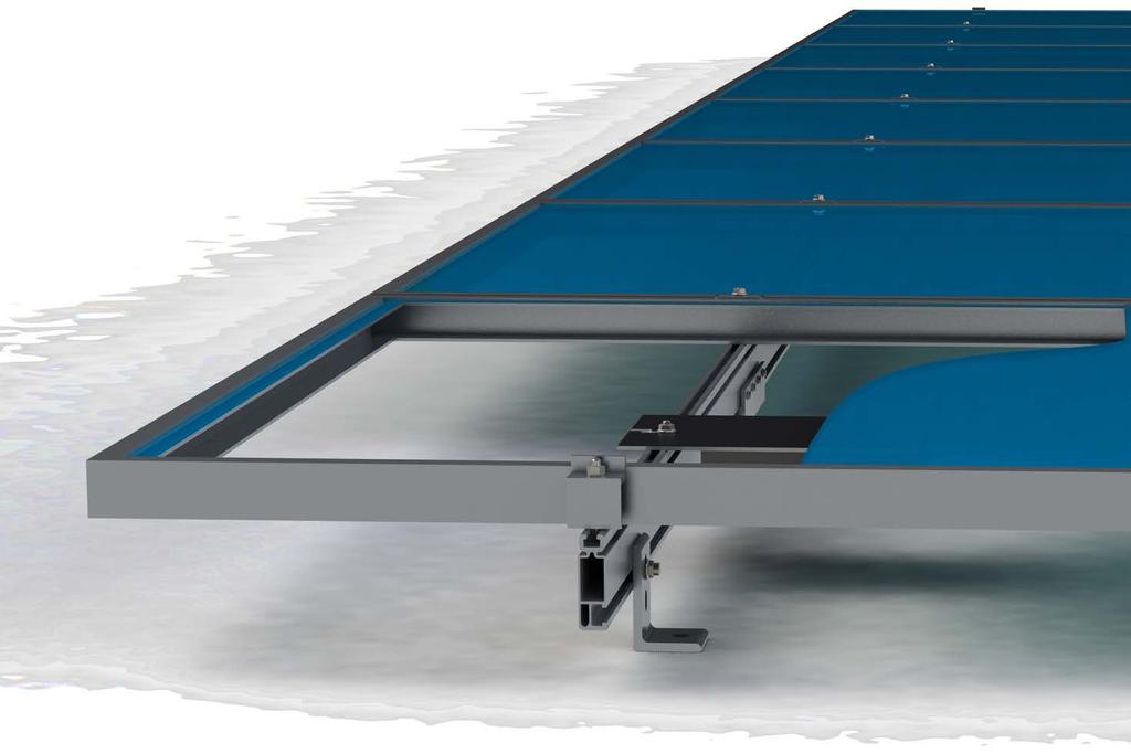
8 SM SOLAR ATTACH RAIL TO L-FEET G 3/8 T-bolt PLACE T-BOLT INTO RAIL: Insert 3/8 T-bolt into rail at L-foot locations. SECURE T-BOLT: Apply Anti-Seize to bolt. Rotate T-bolt into position. CONNECT RAIL TO L-FOOT: Raise rail to upright position and attach to L-feet to T-bolt with 3/8" Serrated Flange Nut. Use either slot to obtain desired height and alignment. ALIGN POSITION INDICATOR: Hand tighten nut until rail alignment is complete. Verify that position indicator on bolt is vertical (perpendicular to rail) TORQUE VALUE (See Note on PG. A) 3/8 nut to 30 ft-lbs Edge Of Installation Area ALIGN RAILS: Align one pair of rail ends to the edge of the installation area. The opposite pair of rail ends will overhang installation area. Do not Trim them off until the installation is complete. If the rails are perpendicular to the rafters, either end of the rails can be aligned, but the first module must be installed at the aligned end. If the rails are parallel to the rafters, the aligned end of the rails must face the lower edge of the roof. Securely tighten all hardware after alignment is complete. Mount modules to the rails as soon as possible. Large temperature changes may bow the rails within a few hours if module placement is delayed.


 /4 nut to 0 ft-lbs w/anti-seize ALIGN POSITION")
9 SM SOLAR MICROINVERTER MOUNTING H INSTALL MICROINVERTER MOUNT T-BOLT: Apply Anti-Seize and install pre-assembled ¼ dia. bonding T-bolts into top ¼ rail slot at microinverter locations. Rotate bolts into position. INSTALL MICROINVERTER: Install microinverter on to rail. Engage with bolt. INSTALL MICROINVERTER: TORQUE VALUE (See Note on PG. A) /4 nut to 0 ft-lbs w/anti-seize ALIGN POSITION INDICATOR: Verify that position indicator on bolt is perpendicular to rail.
 is built into the Enphase Engage integrated grounding (IG) cabling.")
10 MICROINVERTER SYSTEM GROUNDING SM EQUIPMENT GROUNDING THROUGH ENPHASE MICROINVERTERS The Enphase M5 and M50 microinverters have integrated grounding capabilities built in. In this case, the DC circuit is isolated from the AC circuit, and the AC equipment grounding conductor (EGC) is built into the Enphase Engage integrated grounding (IG) cabling. In order to ground the SOLARMOUNT racking system through the Enphase microinverter and Engage cable assembly, there must be a minimum of three PV modules connected to the same trunk cable within a continuous row. Continuous row is defined as a grouping of modules installed and bonded per the requirements of this installation guide sharing the same two rails. The microinverters are bonded to the SOLARMOUNT rail via the mounting hardware. Complete equipment grounding is achieved through the Enphase Engage cabling with integrated grounding (IG). No additional EGC grounding cables are required, as all fault current is carried to ground through the Engage cable. SOLARMOUNT INTEGRATED BONDING ADVANTAGE WITH SYSTEM GROUNDING THROUGH ENPHASE MICROINVERTERS AND TRUNK CABLES LOSE ALL THE COPPER & LUGS I
 3 Microinverters sharing same trunk cable & rails ELECTRICAL GROUNDING W/ ENPHASE MICROINVERTER FOR SPLICE & THERMAL BREAK I- EXPANSION JOINT W/GROUNDING LUGS & COPPER JUMPER Enphase")
 3 or more Microinverters sharing same trunk cable & rails EXPANSION JOINT W/O ELECTRICAL BONDING CONNECTION Enphase M5 & M50) MIn.")
11 CONTINUOUS RAIL & ELECTRICAL BONDING SPLICE Enphase Microinverter (MI) Requirements (Model No. M5 & M50) 3 Microinverters sharing same trunk cable & rails ELECTRICAL GROUNDING W/ ENPHASE MICROINVERTER FOR SPLICE & THERMAL BREAK I- EXPANSION JOINT W/GROUNDING LUGS & COPPER JUMPER Enphase Microinverter (MI) Requirements (Model No. M5 & M50) 3 or more Microinverters sharing same trunk cable & rails EXPANSION JOINT W/O ELECTRICAL BONDING CONNECTION Enphase Microinverter (MI) Requirements (Model No. M5 & M50) MIn. 3 Microinverters on each side of thermal break MINIMUM LAYOUT REQUIREMENTS MINIMUM LAYOUT REQUIREMENTS MINIMUM LAYOUT REQUIREMENTS Min. 3 microinverters sharing same trunk cable & rails RAIL SPLICE 3 or more microinverters sharing same trunk cable & rails RAIL SPLICE THERMAL BREAK Min. 3 microinverters on each side of thermal break RAIL SPLICE THERMAL BREAK Min. 3 microinverters sharing same trunk cable & rails Less than 3 microinverters on each side of thermal break RAIL SPLICE NOT ACCEPTABLE ELECTRICAL BONDING SPLICE EXPANSION JOINT USED AS THERMAL BREAK W/ GROUNDING LUGS & COPPER JUMPER EXPANSION JOINT USED AS THERMAL BREAK W/O ELECTRICAL BONDING CONNECTION NOTE: THE ABOVE IMAGES ARE SAMPLE CONFIGURATIONS TO ILLUSTRATE THE REQUIREMENTS FOR SM SYSTEM GROUNDING THROUGH ENPHASE MICROINVERTERS DESCRIBED ON PAGE I-


12 STANDARD SYSTEM GROUNDING I-3 ONLY ONE LUG PER ROW OF MODULES: Only one lug per row of modules is required. See Page F for additional lugs required for expansion joints. WEEBLUG CONDUCTOR - UNIRAC P/N 00800S: Apply Anti Seize and insert a bolt in the aluminum rail and through the clearance hole in the stainless steel flat washer. Place the stainless steel flat washer on the bolt, oriented so the dimples will contact the aluminum rail. Place the lug portion on the bolt and stainless steel flat washer. Install stainless steel flat washer, lock washer and nut. Tighten the nut until the dimples are completely embedded into the rail and lug. TORQUE VALUE 0 ft lbs. (See Note on PG. A) See product data sheet for more details, Model No. WEEB-LUG-6.7 GROUNDING LUG MOUNTING DETAILS: Details are provided for both the WEEB and Ilsco products. The WEEBLug has a grounding symbol located on the lug assembly. The Ilsco lug has a green colored set screw for grounding indication purposes. Installation must be in accordance with NFPA NEC 70, however the electrical designer of record should refer to the latest revision of NEC for actual grounding conductor cable size. Required if not using approved integrated grounding microinveters GROUNDING LUG - BOLT SIZE & DRILL SIZE GROUND LUG BOLT SIZE DRILL SIZE WEEBLug 7/6 N/A - Place in Top SM Rail Slot IlSCO Lug #0-3 7/3" Torque value depends on conductor size. See product data sheet for torque value. ILSCO LAY-IN LUG CONDUCTOR - UNIRAC P/N P: Alternate Grounding Lug - Drill and bolt thru both rail walls per table. TORQUE VALUE 5 ft lbs. (See Note on PG. A) See product data sheet for more details, Model No. GBL-4DBT.


13 SM SOLAR ENDCLAMP & FIRST MODULE J INSTALL MODULE ENDCLAMPS: The Endclamp is supplied as an assembly with a T-bolt, serrated flange nut, and two washers. One washer retains the clamp at the top of the assembly. The other washer should be against the bolt head during assembly. This will enable the clamp to remain upright for module installation. INSERT ENDCLAMP T-BOLT: Insert /4 T-bolt into rail. ROTATE ENDCLAMP T-BOLT: Rotate T-bolt into position. Verify that the position indicator & T-bolt shaft are angled in the correct position. End clamps are positioned on rails prior to the first end module and installed after the last end module. /" MIN. INSTALL FIRST MODULE: Install the first end module onto rails. Engage module frame with Endclamps. Verify that the position indicator & T-bolt shaft are angled in the correct position. TORQUE VALUE (See Note on PG. A) /4 nuts to 0 ft-lbs. w/anti Seize POSITION INDICATOR - SERRATED T-BOLT: Verify the T-bolt position indicator is perpendicular to the rail.


14 BONDING MIDCLAMP K INSTALL MIDCLAMPS: Midclamp is supplied as an assembly with a T-bolt for module installation. Clamp assemblies may be positioned in rail near point of use prior to module placement. INSERT MIDCLAMP T-BOLT: Apply Anti-Seize and insert /4 T-bolt into rail. ROTATE MIDCLAMP T-BOLT: Rotate bolt into position and slide until bolt and clamp are against module frame. Do not tighten nut until next module is in position. Verify that the position indicator & T-bolt shaft are angled in the correct position. POSITION INDICATOR - SERRATED T-BOLT: Verify the T-bolt position indicator is perpendicular to the rail.
 & T-bolt shaft(s) are angled in the correct position. NOTE: Apply Anti-Seize to each Mid Clamp prior to installation.")

15 SM SOLAR REMAINING MODULES L INSTALL REMAINING MID-CLAMPS: Proceed with module installation. Engage each module with previously positioned Midclamp assemblies. POSITION T-BOLT ALIGNMENT MARKS: Verify that the position indicator(s) & T-bolt shaft(s) are angled in the correct position. NOTE: Apply Anti-Seize to each Mid Clamp prior to installation. TORQUE VALUE (See Note on PG. A) /4 nuts to 0 ft-lbs. w/anti Seize FINISH MODULE INSTALLATION: Proceed with module installation. Engage each module with the previously positioned clamp assembly: Install second module Install remaining Midclamps & modules Install Endclamps Position alignment marks Cut rail to desired length /" MIN. INSTALL ENDCLAMPS: Apply Anti-Seize and install final Endclamps in same manner as first Endclamps. Slide clamps against module. TORQUE VALUE (See Note on PG. A) /4 nuts to 0 ft-lbs. w/anti Seize POSITION T-BOLT ALIGNMENT MARKS & CUT RAIL: Verify that the position indicator(s) & T-bolt shaft(s) are angled in the correct position. Trim off any excess rail, being careful not to cut into the roof. Allow ½ between the Endclamp and the end of the rail.


16 SM RAIL SM SOLAR MODULE FRAME Stainless steel Midclamp points, per module, pierce module frame anodization to bond module to module through clamp. Serrated flange nut bonds stainless steel clamp to stainless steel T-bolt Serrated T-bolt head penetrates rail anodization to bond T-bolt, nut, clamp, and modules to grounded SM rail. BONDING CONNECTION GROUND PATHS M MODULE FRAME BONDING MIDCLAMP ASSEMBLY ENDCLAMP ASSEMBLY BONDING RAIL SPLICE BAR RAIL TO L-FOOT w/bonding T-BOLT Serrated flange nut bonds aluminum Endclamp Stainless steel self drilling screws drill and tap to stainless steel T-bolt into splice bar and rail creating bond between 3 MODULE FRAME BONDING T-BOLT 3 SM RAIL Serrated T-bolt head penetrates rail anodization to bond T-bolt, nut, and Endclamp to grounded SM rail Note: End clamp does not bond to module frame. SERRATED NUT BONDING T-BOLT SM RAIL SPLICE BAR SELF DRILLING SCREWS splice bar and each rail section Aluminum splice bar spans across rail gap to create rail to rail bond. Rail on at least one side of splice will be grounded. Note: Splice bar and bolted connection are non-structural. The splice bar function is rail alignment and bonding. SERRATED FLANGE NUT L-FOOT SM RAIL Serrated flange nut removes L-foot anodization to bond L-Foot to stainless steel T-bolt Serrated T-bolt head penetrates rail anodization to bond T-bolt, nut, and L-foot to grounded SM rail BONDING T-BOLT ENDCLAMP ASSEMBLY Note: Only one lug per module row required RACK SYSTEM GROUND BONDING MIDCLAMP ASSEMBLY BONDING MICROINVERTER MOUNT RAIL TO L-FOOT w/bonding T-BOLT BONDING RAIL SPLICE BAR HEX NUT W/ CAPTIVE LOCK WASHER BONDING T-BOLT MICRO-INVERTER FLANGE SEE NOTE SM RAIL BONDING MICROINVERTER MOUNT Hex nut with captive lock washer bonds metal microinverter flange to stainless steel T-bolt Serrated T-bolt head penetrates rail anodization to bond T-bolt, nut, and L-foot to grounded SM rail System ground including racking and modules may be achieved through the trunk cable of approved microinverter systems. See page I for details SOLID COPPER WIRE WEEBLUG (OR ILSCO LUG) RACK SYSTEM GROUND WEEB washer dimples pierce anodized rail to create bond between rail and lug Solid copper wire connected to lug is routed to provide final system ground connection. NOTE: Ilsco lug can also be used when secured to the side of the rail. See page I-3 for details SM RAIL


17 BONDING CONNECTION GROUND PATHS N BONDING MID CLAMPS MAINTAIN GROUND PATH TEMPORARY BONDING CONNECTION MODULE REMOVED REQUIRED ONLY FOR TEMPORARY BONDING DURING ARRAY MAINTENANCE Ilsco SGB-4 SOLID COPPER WIRE Ilsco SGB-4 ELECTRICAL CONSIDERATIONS SOLARMOUNT is intended to be used with PV modules that have a system voltage less than or equal to 000 VDC. For standard system grounding a minimum 0AWG, 05 C copper grounding conductor should be used to ground a 000 VDC system, according to the National Electric Code (NEC). It is the installer s responsibility to check local codes, which may vary. See below for interconnection information. INTERCONNECTION INFORMATION There is no size limit on how many SOLARMOUNT & PV modules can be mechanically interconnected for any given configuration, provided that the installation meets the requirements of applicable building and fire codes. TEMPORARY BONDING CONNECTION DURING ARRAY MAINTENANCE When removing modules for replacement or system maintenance, any module left in place that is secured with a bonding Midclamp will be properly grounded. If a module adjacent to the end module of a row is removed or if any other maintenance condition leaves a module without a bonding mid clamp, a temporary bonding connection must be installed as shown Attach Ilsco SGB4 to wall of rail Attach Ilsco SGB4 to module frame Install solid copper wire jumper to Ilsco lugs GROUNDING NOTES The installation must be conducted in accordance with the National Electric Code (NEC) and the authority having jurisdiction. Please refer to these resources in your location for required grounding lug quantities specific to your project. The grounding / bonding components may overhang parts of the array so care must be made when walking around the array to avoid damage. Conductor fastener torque values depend on conductor size. See product data sheets for correct torque values.
INSTALLATION GUIDE SM SOLAR MOUNT PUB15JAN01
 MOUNT INSTALLATION GUIDE PUB5JAN0 SM SOLAR Wrenches and Torque Wrench Size Recommended Torque (ft-lbs) /4 Hardware 7/6 *0 3/8 Hardware 9/6 *30 # Hardware 5/6 0 Torques are not designed for use with wood
SolarMount (E)volution
volution") SolarMount (E)volution SOLARMOUNT (E)VOLUTION: THE BEST JUST GOT BETTER. Engineering, Excellence, and Ease. Performance Engineered for versatility and reduced installation time, SolarMount (E)volution
SolarMount (E)volution SOLARMOUNT (E)VOLUTION: THE BEST JUST GOT BETTER. Engineering, Excellence, and Ease. Performance Engineered for versatility and reduced installation time, SolarMount (E)volution
SolarMount-I INSTALLATION MANUAL Broadway Boulevard NE Albuquerque, NM USA A HILTI GROUP COMPANY
 SolarMount-I INSTALLATION MANUAL 2011 by Unirac, Inc. All rights reserved. Pub 110518-1ii, May 2011 A HILTI GROUP COMPANY R 1411 Broadway Boulevard NE Albuquerque, NM 87102-1545 USA IMPORTANT! Unirac Inc.
SM SOLAR INSTALLATION GUIDE MOUNT REV2017DEC01
 MOUNT TABLE OF CONTENTS A - SYSTEM COMPONENTS B - SYSTEM LAYOUT C - CODE COMPLIANCE NOTES D - ROOF ATTACHMENT & L-FEET E - SPLICE & THERMAL BREAK F - ATTACH RAIL TO L-FEET G - MICROINVERTER MOUNTING H
SunPower Installation Manual
 SunPower SF System Planning and Assembly SunPower SUNPOWER CORPORATION WWW.SUNPOWERCORP.COM Pub #101001-SP2 October 2010 - Rev. 8 2010 by SunPower, Corp All rights reserved. Part I. Scope, components,
INSTALLATION GUIDE FRAME MICRORAIL PUB2017JUL18
 MICRORAIL INSTALLATION GUIDE TABLE OF CONTENTS A- TOOLS & SPECIFICATIONS B- SYSTEM COMPONENTS C- SYSTEM COMPONENTS D- SYSTEM COMPONENTS E - SYSTEM LAYOUT F- THERMAL EXPANSION LIMITS G- FLASHING & SLIDERS
SolarMount-I INSTALLATION MANUAL
 SolarMount-I INSTALLATION MANUAL 2010 by Unirac, Inc. All rights reserved. Pub 100621-1ii, June 2010 R A HILTI GROUP COMPANY 1411 Broadway Boulevard NE Albuquerque, NM 87102-1545 USA IMPORTANT! Unirac
AWNING SYSTEM INSTALLATION INSTRUCTIONS ALL VERTICAL WALLS
 INSTALLATION MANUAL AWNING SYSTEM INSTALLATION INSTRUCTIONS ALL VERTICAL WALLS TABLE OF CONTENTS Table of Contents... 3 Components... 4 System Components... 6 Attachment Components... 7 Module Compatibility...
Patented Rail-Free Mounting System for Composition/Asphalt Shingle Roofs
 Quick Start Guide Patented Rail-Free Mounting System for Composition/Asphalt Shingle Roofs R ESPECT T HE R OOF Quick Rack Components & Tools Components are pre-assembled and ready for installation right
Outline. Grounding Washer, Electrical Equipment Bond (WEEB) Acme Cable Clips Acme Conduit Entry (ACE) Questions
 Acme Cable Clips Acme Conduit Entry (ACE) Questions") www.we-llc.com Outline Grounding Washer, Electrical Equipment Bond (WEEB) Acme Cable Clips Acme Conduit Entry (ACE) Questions Bonding & Grounding Grounding Terms Equipment Grounding: The National Electrical
www.we-llc.com Outline Grounding Washer, Electrical Equipment Bond (WEEB) Acme Cable Clips Acme Conduit Entry (ACE) Questions Bonding & Grounding Grounding Terms Equipment Grounding: The National Electrical
INSTALLATION GUIDE SOLAR MOUNT REV2018SEP11
 SM SOLAR MOUNT TABLE OF CONTENTS A - SYSTEM COMPONENTS B - SYSTEM LAYOUT C - CODE COMPLIANCE NOTES D - ROOF ATTACHMENT & L-FEET E - SPLICE & THERMAL BREAK F - ATTACH RAIL TO L-FEET G - MICROINVERTER MOUNTING
ROOF MOUNT. *Class A* Fire Rated INSTALLATION MANUAL
 ROOF MOUNT 4008083 *Class A* Fire Rated INSTALLATION MANUAL Contents DISCLAIMER 1 RATINGS 1 CHECKLIST 2 PRIMARY COMPONENTS 3 1. ATTACH BASES 3 2. PLACE RAILS 3 3. SECURE LUG 4 4. CLAMP MODULES 4 EXPANSION
BLACK WIDOW COMPOSITE
 PAGE-1 UPDATED 3-6-2015 REV.1 BLACK WIDOW COMPOSITE Detailed installation manual PAGE-2 UPDATED 3-6-2015 SpiderRax, Inc. REVISION PAGE Installation Manual For BWC-S, BWC-B,BWC-F DATE PAGES REASON OLD LEVEL
Solar Mounting Solutions. Series 100 Residential Roof Mount System Installation Manual. snapnrack.com Listed PV Mounting System
 Solar Mounting Solutions Series 100 Residential Roof Mount System Installation Manual 2703 Listed PV Mounting System An Intro to SnapNrack Series 100 SnapNrack Series 100 PV Mounting System offers a low
UPDATED REV.5 BLACK WIDOW. Detailed installation manual. Patent pending P/N: BW-S, BW-B, BW-F.
 PAGE-1 UPDATED 2-3-2015 REV.5 BLACK WIDOW Detailed installation manual PAGE-2 UPDATED 2-3-2015 SpiderRax, Inc. REVISION PAGE Installation Manual For BW-S, BW-B,BW-F DATE PAGES REASON OLD LEVEL NEW LEVEL
Flush Mount. SunEarth Flush Mount Installation Manual. SunEarth Flush Mount. Asphalt Shingle Roofing
 Flush Mount SunEarth Flush Mount Installation Manual Thank you for choosing the SunEarth flush mount method. It provides a strong durable solution for mounting SunEarth collectors parallel to the roof
ROOF MOUNT. *Class A* Fire Rated INSTALLATION MANUAL
 ROOF MOUNT 4008083 *Class A* Fire Rated INSTALLATION MANUAL CONTENTS DISCLAIMER 1 RATINGS 1 CHECKLIST 2 PRIMARY COMPONENTS 3 0. ATTACH BASES 3 1. PLACE RAILS 3 2. SECURE LUG 4 3. CLAMP MODULES 4 EXPANSION
Rayport G Eco Dealer Kit
 Rayport G Eco Dealer Kit Installation Guide www.aetenergy.com Supporting a Cleaner, Greener Tomorrow 1. Table of Contents 1. Table of Contents P2 2. Installer Notes P3 3. Parts List P4-7 4. Tool List P8
PV Mounting System 2703 SERIES 100 UL ROOF MOUNT SYSTEM. SnapNrack Residential PV Mounting Systems Code Compliant Installation Manual
 PV Mounting System 2703 SERIES 100 UL ROOF MOUNT SYSTEM SnapNrack Residential PV Mounting Systems Code Compliant Installation Manual Series 100 UL Intro/Configuration Series 100 UL Introduction SnapNrack
orientation Conergy SunTop Instructions for professional installation
 On-roof Framed modules Portrait orientation Landscape Three-tab Shingle Plain tile Slate Double Roman tile Metal roof Material warranty orientation Conergy SunTop Instructions for professional installation
May 14, Installation Manual
 May 14, 2012 Installation Manual Contents MAG TRACKER Components...1 Mount Installation...7 Module Installation & Grounding...11 Maintenance...14 Warranty......14 Contact Information......14 May 14, 2012
CSS Central Mount System
 CSS-20 Installation Manual CSS-20 Safety Notifications Below are the installation instructions for the CSS-20-2 Long Span Beam Mounting System. Please read these safety notifications prior to beginning
INSTALLATION MANUAL v. 1.0
 INSTALLATION MANUAL v. 1.0 2009 by Unirac, Inc. All rights reserved. Pub 090501-1ii, May 2009 www.clicksys-beam.com IMPORTANT! Unirac Inc. makes no warranty of any kind with regard to this material, including,
Installation Instructions for Solar Snow Pad (SSP-T-3)
") Installation Instructions for Solar Snow Pad (SSP-T-3) Warning- Do not use this product on solar arrays where the calculated array snow loads exceed 50 pounds per square foot (psf). Most solar panels are
Installation Instructions for Solar Snow Pad (SSP-T-3) Warning- Do not use this product on solar arrays where the calculated array snow loads exceed 50 pounds per square foot (psf). Most solar panels are
Clearview Railing System Installation Instructions
 Clearview Railing System Installation Instructions Disclaimer: AGS Stainless, Inc. has its Clearview Railing Systems designed by a professional engineer to meet the requirements of the latest national
Rayport G Eco Ballasted
 Rayport G Eco Ballasted Dealer Kit Installation Guide Contents 1. Installer Notes..... P2 2. Parts List........ P3-6 3. Tool List.... P7 4. Assembly.... P8-16 www.aetenergy.com Supporting a Cleaner, Greener
Unirac Installation Manual
 Tile Roof Hook Universal Mount Unirac R Pub 120803-1ii August 2012 A HILTI GROUP COMPANY Unirac welcomes input concerning the accuracy and user-friendliness of this publication. Please write to publications@unirac.com.
Standard Rail Roof Mounting System Design Manual
 Standard Rail Roof Mounting System Design Manual Standard Rail (XRS) Splice Addendum... 2 Standard Rail (XRS) Flush Span Chart... 4 Standard Rail (XRS) Tilt Span Chart... 5 IronRidge Roof Mount Attachment
1 of 9 SITE PLAN modules at 325W kw. Sample GAMECHANGE SOLAR. Sample. Sample AERIAL VIEW. Array Information. Design Information.
 AERIAL VIEW Array Information PV Modules Racking Manufacturer Hyundai Gamechange Racking Model HiS-S325TI 5-Degree GC Grid-Lite Dimensions." x 39.29" x.9" Weight 5. lbs Quantity 224 224 modules at 325W
Flush Mount Kit. SunEarth Flush Mount Kit Installation Manual. SunEarth Flush Mount Kit. Asphalt Shingle Roofing
 Flush Mount Kit SunEarth Flush Mount Kit Installation Manual Thank you for purchasing the SunEarth flush mount kit. The flush mount kit (MTG-EC-FM) is our simplest and least expensive mounting system.
Rayport G Eco Dealer Kit
 Rayport G Eco Dealer Kit Installation Guide Contents 1. Installer Notes..... P2 2. Parts List........ P3-7 3. Tool List.... P8 4. Assembly.... P9-19 www.aetenergy.com Supporting a Cleaner, Greener Tomorrow
CONTENTS TOOL LIST U P S I D E I N N O V A T I O N S, L L C RAMP AND STEP SYSTEM ASSEMBLY INSTRUCTIONS. Revised: June 2013
 U P S I D E I N N O V A T I O N S, L L C RAMP AND STEP SYSTEM ASSEMBLY INSTRUCTIONS TOOL LIST Required Tools: - Reciprocating Saw with Metal Cutting Blade - Drill - 7/16 Drill Bit for Metal Drilling -
Unirac Installation Manual
 Tile Roof Hook Universal Mount Unirac R Pub 090727-1ii June 2009 A HILTI GROUP COMPANY Unirac welcomes input concerning the accuracy and user-friendliness of this publication. Please write to publications@unirac.com.
PV MOUNTING SYSTEM INSTALLATION MANUAL
 PV MOUNTING SYSTEM INSTALLATION MANUAL The ROOF TRAC PV mounting system makes the installation of PV modules for rooftop installations easy, safe and attractive. The patented (pat #6,360,491) PV support
On-Roof Mounting Sets for Flat-Plate Collectors
 Engineering Submittal Sheet Installation sets for collectors Fig. 1 Installation set for 2 collectors 1 basic installation set, 1 extension installation set Basic installation set for each collector array
EZ Tile Hook System. SunModo PV Rack Mount System UL2703 Compliant
 SunModo PV Rack Mount System UL2703 Compliant Pub. D10007-V005 Copyright 2016 Please read carefully before installing Product is tested to and recognized to UL 2703 standards for safety grounding and bonding
Series 100 Roof Mount
 Series 100 Roof Mount Code Compliant Installation Manual 2011 Table of Contents 1. INTRODUCTION...3 1.1 OVERVIEW OF THE SNAPNRACK SYSTEM...3 1.2 OVERVIEW OF THIS MANUAL...4 1.3 YOUR RESPONSIBILITY AS INSTALLER...4
1 of 6 SITE PLAN MW. Sample GAMECHANGE SOLAR. Sample. Sample AERIAL VIEW. Array Information. Design Information. Racking.
 AERIAL VIEW Array Information PV Modules Racking Manufacturer NEO Solar Gamechange Racking Model D6M-B4A 23-Degree MaxSpan Dimensions Weight 77.0"x39.1"x1.57" 56.2 lbs Quantity 5184 407 Ground learance
Roof Mount Ground Mount Specialised Clamps Spares Application Notes
 DPA Solar Racking Solutions Solar PV Racking Catalogue Roof Mount Ground Mount Specialised Clamps Spares Application Notes www.dpasolar.com.au 1300 447 500 Rails & Splices Page 3 Mid & End Clamps Page
Installation Manual FLUSH MOUNT - Shingle, Slate,etc. Questions? Call Us! +1 (800)
") www.trasnowandsun.com S Installation Manual FLUSH MOUNT - Shingle, Slate,etc. At TRA Snow and Sun we engineer and layout each project upon request free of charge. Just give us the project details and we
www.trasnowandsun.com S Installation Manual FLUSH MOUNT - Shingle, Slate,etc. At TRA Snow and Sun we engineer and layout each project upon request free of charge. Just give us the project details and we
GlideRite Retractable Cover System For HotSpring & Tiger River Spas (except Classic & pre-2000 Landmark Spas)
") List of Contents Quantity Description 12 #10 x 1 ½ Flat Head Phillips Screw (see pg. 2) 2 #10 x ½ Pan Head Phillips Screw (see pg. 2) 8 ¼ x 2 ½ Lag Bolt (see pg. 2) 7 ¼ 20 x 5 / 8 Hex Head Bolt (see pg.
List of Contents Quantity Description 12 #10 x 1 ½ Flat Head Phillips Screw (see pg. 2) 2 #10 x ½ Pan Head Phillips Screw (see pg. 2) 8 ¼ x 2 ½ Lag Bolt (see pg. 2) 7 ¼ 20 x 5 / 8 Hex Head Bolt (see pg.
Installation Instructions - Model V4JSD 1
 Installation Instructions - Model V4JSD 1 Support Assemblies: Parts list: (Note see enclosed cut sheet for quantities and dimensional information) A vertical structural member (1 ½ x 1 ½ modular frame)
Installation Manual for The Asphalt/Bitumen Shingle Roof Hook System
 Installation Manual for The Asphalt/Bitumen Shingle Roof Hook System (F-IMG-1534-SolNV) Installation of Asphalt/Bitumen Shingle Roof Hook System Installing Rail / Purlin System Installing Cross Rail System
Dura-Lock Roof System
 DLR-14 Dura-Lock Roof System Assembly and Installation Instructions Read the instructions before starting the job. They explain the steps required to produce a finished product that will meet factory specifications.
Installation Manual Tilt Leg
 Installation Manual Tilt Leg Solar Mounting Solutions March www.ironridge.com 2010 IronRidge, Inc. All Rights Reserved Version 2.0 2 Tilt Leg Installation Guide Introduction The Tilt Leg is a flexible
Installation Instructions for Solar SnowMax (SSM) Series of Snow Retention Products
 Series of Snow Retention Products") Installation Instructions for Solar SnowMax (SSM) Series of Snow Retention Products Warning- Do not use this product on solar arrays where the ground snow loads exceed 50 pounds per square foot (psf).
Installation Instructions for Solar SnowMax (SSM) Series of Snow Retention Products Warning- Do not use this product on solar arrays where the ground snow loads exceed 50 pounds per square foot (psf).
TABLE OF CONTENTS REQUIRED TOOLS
 TABLE OF CONTENTS SECTION SECTION TITLE PAGE NO. 1 2 3 4 5 Assembling Mounting Structure Installing Bicycle Supports Mounting Rack to Wall Adding Sections Customizing Rack Configuration REQUIRED TOOLS
Empire & SunWise Collectors. Imperial Collectors. Copperheart ICS (asphalt shingles)
") Standoff Mounting Standoff mounting is the simplest and most cost effective way to install SunEarth solar collectors on sloped roof surfaces. Standoff mounting components are designed to lift the collectors
Standoff Mounting Standoff mounting is the simplest and most cost effective way to install SunEarth solar collectors on sloped roof surfaces. Standoff mounting components are designed to lift the collectors
Horizontal Cable Systems
 ALUMINUM RAILING INSTALLATION INSTRUCTIONS v2012 orizontal Cable Systems 1) Check Contents Of Packages: Verify that all parts have arrived and that they match the packing list. 1A) Coastal applications:
INSTALLATION INSTRUCTIONS
 INSTALLATION INSTRUCTIONS R5 STEP BOARD APPLICATION: 2009-2017 Dodge Ram 1500 Quad / Crew Cab 2010-2017 Dodge Ram 2500/3500 Crew Cab PART NUMBER: 28-51040, 28-51045, 28-51050, 28-51055 ITEM QUANTITY DESCRIPTION
EzQuikTM. MicroSolar System EzQuik TM Aluminum Solar PV Module Mounting System. Code-Compliant Installation Manual V1011 (AS/NZ1170) Model 2012
 Model 2012") TM Model 2012 Code-Compliant Installation Manual V1011 (AS/NZ1170) MicroSolar System TM Aluminum Solar PV Module Mounting System 1 CONTENTS SECTION 1 INTRODUCTION... 3 1.1... 3 1.2 Why?... 3 1.3 Before
TM Model 2012 Code-Compliant Installation Manual V1011 (AS/NZ1170) MicroSolar System TM Aluminum Solar PV Module Mounting System 1 CONTENTS SECTION 1 INTRODUCTION... 3 1.1... 3 1.2 Why?... 3 1.3 Before
Installation Manual XRL Solar Rail System
 Installation Manual XRL Solar Rail System Solar Mounting Solutions June 2009 www.ironridge.com 2009 IronRidge, Inc. All Rights Reserved Version 1.0 2 XRL Solar Rail System Installation Guide Introduction
SolarWedge. Installation Manual Date Modified: 9/17/07 WARNING SAFETY. Tool List
 APPLICATION: The product line provides an easy -to-install and economical solution for a 5, 10 or 15 degree tilted roof mounted system. integrates with Professional Solar s (ProSolar) patented top-down
User Instructions Multiline Otter Scoreboard Caddy Assembly
 List of parts: User Instructions Multiline Otter Scoreboard Caddy Assembly Single Caddy Double Caddy 1 1 Base assembly with attached wheels 2 4 1 1 2 4 4 8 10 20 12 Uprights (60 or 74 aluminum extrusion)
Installation Manual. Roof Tech,Inc. 5/2014. Contents
 5/2014 Installation Manual Contents Introduction 1 Installation Safety 2 ools & Supplies Required For Assembly 3 1.Installation on rafter 4 2.Installation on deck 16 3.Panel installation 29 Roof ech,inc.
POWER PEAK TM ASSEMBLY INSTRUCTIONS. step-by-step assembly and installation. Version 1, Rev D P/N
 POWER PEAK TM ASSEMBLY ISTRUCTIOS step-by-step assembly and installation Version 1, Rev D P/ 5803028 The Power Peak TM A few words about this product The Power Peak is designed to mount on standard I-Beams
Horizontal Cable Systems
 ALUMINUM RAILING INSTALLATION INSTRUCTIONS Horizontal Cable Systems 1) Check Contents Of Packages: Verify that all parts have arrived and that they match the packing list. 1A) Coastal applications: Confirm
GlideRite Retractable Cover System For Hot Spot Spas (SE & SLX only)
") List of Contents Quantity Description 12 #10 x 1 ½ Flat Head Phillips Screw (see pg. 2) 2 #10 x ½ Pan Head Phillips Screw (see pg. 2) 8 ¼ x 2 ½ Lag Bolt (see pg. 2) 7 ¼ 20 x 5 / 8 Hex Head Bolt (see pg.
List of Contents Quantity Description 12 #10 x 1 ½ Flat Head Phillips Screw (see pg. 2) 2 #10 x ½ Pan Head Phillips Screw (see pg. 2) 8 ¼ x 2 ½ Lag Bolt (see pg. 2) 7 ¼ 20 x 5 / 8 Hex Head Bolt (see pg.
28" Adjustable Solar Tilt Mount ADJ-28. Owner's Manual. Please read this manual BEFORE installing your solar tilt mount
 28" Adjustable Solar Tilt Mount ADJ-28 Owner's Manual Please read this manual BEFORE installing your solar tilt mount SECTION 1 Introduction Mounting your solar panel inclined to an optimized angle with
Project A. AC Section 4.1 Rain Test of V1 and V2 Tile Base With Butyl Strips. For
 Project 16-258A AC286-12 Section 4.1 Rain Test of V1 and V2 Tile Base With Butyl Strips For EcoFasten Solar 4741 W. Polk Street, Suite 4 Pheonix, AZ 85043 PFS Corporation dba PFS TECO Cottage Grove Laboratory
Assembly Instructions 10 X 10 Aluminum Roof Support
 Assembly Instructions 10 X 10 Aluminum Roof Support Aluminum Roof Support Bolt Package 16-5/16 X 2 ¼ SS Bolt 24-5/16 X 1 SS Bolt 40-5/16 SS Nylon Lock Nuts 16-5/16 SS Flat Washers 28-4 ½ Wood Screws 36-1
MTS-ACB. RENOGY Photovoltaic Module Adjustable Curved Bracket E Philadelphia St, Ontario, CA Version: 1.
 MTS-ACB RENOGY Photovoltaic Module Adjustable Curved Bracket 2775 E Philadelphia St, Ontario, CA 91761 1-800-330-8678 1 Version: 1.0 Important Safety Instructions Please save these instructions. This manual
MobileTrak5 Installation Instructions
 MobileTrak5 Installation Instructions PLEASE OPEN ALL BOXES & CHECK TO MAKE SURE YOU HAVE ALL PIECES REQUIRED READ ALL INSTRUCTIONS BEFORE STARTING Tools Required for Assembly 7/16, 1/2 Wrench Phillips
MTS-ZB. RENOGY Photovoltaic Module Z-Bracket Mounting System E Philadelphia St, Ontario, CA Version: 1.
 MTS-ZB RENOGY Photovoltaic Module Z-Bracket Mounting System 2775 E Philadelphia St, Ontario, CA 91761 1-800-330-8678 1 Version: 1.0 Important Safety Instructions Please save these instructions. This manual
Installing Quick Mount PV Products on. Metal Shingle Roofs RESPECT THE ROOF
 Installing Quick Mount PV Products on Metal Shingle Roofs RESPECT THE ROOF Getting Started Steel Shingle Roofing Flashing Method and Product Type Terminology Flashing QBase Mount Interlocking Steel Shingle
Catalog. Mounts. Racking. Systems. Rail Clamps L-Feet. Pub. C10001-V016
 Catalog Mounts Racking Rail Clamps L-Feet Systems Pub. C10001-V016 Copyright 2018 On behalf of our organization, thank you for considering SunModo for your racking needs. At SunModo, we are dedicated to
Installation Guide. 203 Chesterra Drive, Dahlonega, GA Toll-Free ~ Fax ~
 Congratulations and Thank You for your purchase! DryJoistEZ is an easy to install structural aluminum joist that also provides an under-deck drainage system that you install over your deck framing system
ALL SEASON PATIO COVER
 ALL SEASON PATIO COVER 61 Where the All Season Patio Cover is to be attached to the home, create a level line showing where the top of the mounting rail is to be located. Install each section with the
Assembly Instructions
 InTandem Table System November 20 InTandem Table System - Worksurface #4 x/" 4 wood screw power beam Tools Provided T-0 Extended Torx Driver T-25 Torx Driver Additional Tools Required Soft protective
EZ Tile Hook System. SunModo PV Rack Mount System UL2703 Compliant
 SunModo PV Rack Mount System UL2703 Compliant Pub. D10007-V007 Copyright 2016 Please read carefully before installing Product is tested to and recognized to UL 2703 standards for safety grounding and bonding
Installation Guide Simplicity Alfresco. V1.9 Lu070318
 0333 305 5272 www.canoports.co.uk Installation Guide Simplicity Alfresco V1.9 Lu070318 Tools Required Below is a list of tools that you will require to install your the Simplicity Alfresco System. Cordless
SWH Solar Racking Installation Guide
 SOLAR WAREHOUSE SWH Solar Racking Installation Guide Version 16.08.v1 9628 Valley Blvd. Rosemead, CA 91770 INSTALLATION Phone 626-579-3288 GUIDE VERSION info@esolarwarehouse.com - 16.08.V1 SOLAR WAREHOUS
TURBOTWISTER ASSEMBLY AND INSTALLATION INSTRUCTIONS
 TURBOTWISTER ASSEMBLY AND INSTALLATION INSTRUCTIONS CORPORATE HEADQUARTERS WESTERN SALES AND MANUFACTURING PLANT P.O. Box 400 1017 SW Berg Parkway Canby, Oregon 97013 Phone: (503) 266-2231 Fax: (503) 266-4334
INSTALLATION INSTRUCTIONS
 INSTALLATION INSTRUCTIONS SPORTSMAN WINCH MOUNT GRILLE GUARD APPLICATION: 2016-2018 Toyota Tacoma PART NUMBER: 40-93885, 45-93880, 46-23885 ITEM QUANTITY DESCRIPTION TOOLS NEEDED 1 1 WINCH TRAY 15MM SOCKET
Pole Mount Installation Manual
 Pole Mount Installation Manual Thank You for Choosing AIMS Power! 1. AIMS Power is a leading supplier of solar products, specializing in PV mounting systems. We ensure our products are manufactured to
Installation Guidelines
 Page 1 Tools You ll Need 4 ft. Carpenter s level Chalk line (to mark U channel locations) Cordless drill/nut driver Caulking gun Chop saw with a metal cutting blade on it (required to make accurate and
MONKEY BARS OVERHEAD RACK INSTALLATION
 MONKEY BARS OVERHEAD RACK INSTALLATION Thank you for purchasing the New Monkey Bars Overhead storage rack. The most innovative overhead rack on the market WARNING THE PROPER INSTALLATION OF THIS STORAGE
SRIS-001 Arista Mounting System Instruction Sheet Solar Rooftop Support Ballasted
 SRIS-001 Arista Mounting System Instruction Sheet Solar Rooftop Support Ballasted 509 West Monroe Street Highland, IL 62249 Phone: (618) 654-2184 Fax: (618) 654-9199 Tools Needed For Installation 1. ¾
TYPHOON ASSEMBLY AND INSTALLATION INSTRUCTIONS
 TYPHOON ASSEMBLY AND INSTALLATION INSTRUCTIONS CORPORATE HEADQUARTERS WESTERN SALES AND MANUFACTURING PLANT P.O. Box 400 1017 SW Berg Parkway Canby, Oregon 97013 Phone: (503) 266-2231 Fax: (503) 266-4334
INDEX PAGE RELEASE SECTION NUMBER DATE
 INSTALLATION INSTRUCTIONS For Wind Zone 1 (other Wind Zones available on request) Version 11/20/2002 INDEX PAGE RELEASE SECTION NUMBER DATE Approval INTRODUCTION 2 2/26/2001 GENERAL INSTALLATION 3 2/26/2001
Lab Style Table Frame Part No Assembly Guide Automation Technology
 Ergonomic Workstations Lab Style Table Frame Part No. 8 0 Assembly Guide 7 90 70 Automation Technology SPECIFICATIONS Lab style frame part number... 80 Height... 70 mm (8.") Width... 90 mm (.7") Depth...
10 x 10 Flat Top Two Tone Pergola
 0 x 0 Flat Top Two Tone Pergola Models: Bordeaux ASSEMBLY GUIDE OPTIONAL ACCESSORIES Arch Kit System ( Arches) Privacy Fence Panel System ( Panels & Middle Post) Bolt Down Bracket Kit ( for Pergola) Ver.0-00
INSTRUCTIONS INSTRUCCIONES CONSIGNES
 AUTOMOTIVE PRODUCTS, INC. INSTRUCTIONS INSTRUCCIONES CONSIGNES APPLICATION: 2007 13 CHEVY SILVERADO 1500 (except Classic ) MAX WINCH TRAY: HDX 46-22275 SPORTSMAN WINCH MOUNT GRILLE GUARD: 45-92270, 40-92275
MTS-SP100. RENOGY Pole Mount System E Philadelphia St, Ontario, CA Version: 1.2
 MTS-SP100 RENOGY Pole Mount System 2775 E Philadelphia St, Ontario, CA 91761 1-800-330-8678 1 Version: 1.2 Important Safety Instructions Please save these instructions. This manual contains important safety,
TURBOTWISTER TM ASSEMBLY AND INSTALLATION INSTRUCTIONS
 TURBOTWISTER TM ASSEMBLY AND INSTALLATION INSTRUCTIONS CORPORATE HEADQUARTERS WESTERN SALES AND MANUFACTURING PLANT P.O. Box 400 1017 SW Berg Parkway Canby, Oregon 97013 Phone: (503) 266-2231 Fax: (503)
Multi-Stage ASSEMBLY INSTRUCTIONS ST-8100 SERIES. 125 TAYLOR PARKWAY ARCHBOLD, OH PHONE: (419) FAX: (419)
 FAX: (419)") 125 TAYLOR PARKWAY ARCHBOLD, OH 43502 PHONE: (419) 445-8915 FAX: (419) 445-0367 www.biljax.com Multi-Stage ST-8100 SERIES ASSEMBLY INSTRUCTIONS ALL DRAWINGS ARE FOR ILLUSTRATION ONLY. PRINTED IN U.S.A.
125 TAYLOR PARKWAY ARCHBOLD, OH 43502 PHONE: (419) 445-8915 FAX: (419) 445-0367 www.biljax.com Multi-Stage ST-8100 SERIES ASSEMBLY INSTRUCTIONS ALL DRAWINGS ARE FOR ILLUSTRATION ONLY. PRINTED IN U.S.A.
Installation Guide Contemporary Alfresco V1.3 LU
 Installation Guide Contemporary Alfresco V1.3 LU 010818 Tools Required Below is a list of tools that you will require to install you're the Contemporary Alfresco System. Cordless Drill Mastic Gun Spirit
Mounting system for sloped composite shingle roofs with solar panels in portrait orientation
 MANUAL USA MOUNTING SYSTEM FOR SLOPED COMPOSITE SHINGLE ROOFS Mounting system for sloped composite shingle roofs with solar panels in portrait orientation ESDEC BV 2016 CONTENT page 1. Introduction 1 2.
Roof Attachment Overview
 Roof Attachment Overview MY STORY Brandon Gwinner Account Executive OUR RACKING SOLUTIONS - Construction and Sales for over 15 years - SunModo brand representative for over 5 years - OSEIA board of Directors
Installation Guide. Step 3. Valley Flashing. Step 7. Transition Flashings and Accessories. Step 6. Hip and Ridge Installation
 Step 7. Transition s and Accessories Step 3. Valley Step 6. Hip and Ridge Installation Step 2. Rake Trim Step 5. Installing the Shingles Step 1. Eave Starter Installation Step 4. Endwall s Installation
CURVED ROOF ASSEMBLY INSTRUCTIONS ATTACHED VERANDAH. Your supplementary guide to building an ATTACHED CURVED ROOF VERANDAH or PATIO BEFORE YOU START
 ROOF ATTACHED VERANDAH ASSEMBLY INSTRUCTIONS Your supplementary guide to building an ATTACHED ROOF VERANDAH or PATIO This set of instructions should be used in conjunction with the Stratco instruction
TURBOTWISTER ASSEMBLY AND INSTALLATION INSTRUCTIONS
 TURBOTWISTER ASSEMBLY AND INSTALLATION INSTRUCTIONS CORPORATE HEADQUARTERS WESTERN SALES AND MANUFACTURING PLANT P.O. Box 400 1017 SW Berg Parkway Canby, Oregon 97013 Phone: (503) 266-2231 Fax: (503) 266-4334
ASSEMBLY INSTRUCTIONS
 Universal Top-of-Pole Mount 8 Modules (UTPM8) Module Type G ASSEMBLY INSTRUCTIONS step-by-step assembly and installation Version 1, Rev A PCN 022714-1 Universal Top-of-Pole Mount 8 Modules (UTPM8) for
Steep-Slope ApplicAtionS
 Steep-Slope ApplicAtionS GreenFasten GF1 PRODUCT GUIDE Exploded Product View/B.O.M. 1 Installation Instructions 2 Cut Sheets 3 Specifications 4 Test Data 5 Price List 6 Exploded Product View, Bill of Materials
INSTALLATION INSTRUCTIONS CONTOURED LIGHT BAR APPLICATION: CHEVY EQUINOX/ GMC TERRAIN PART NUMBERS: ,
 INSTALLATION INSTRUCTIONS CONTOURED LIGHT BAR APPLICATION: 2010-2014 CHEVY EQUINOX/ GMC TERRAIN PART NUMBERS: 32-21020, 32-21025 ITEM QUANTITY DESCRIPTION TOOLS NEEDED 1 1 CONTOUR BAR TORQUE WRENCH 2 1
Catalog. Mounts. Racking. Systems. Rail Clamps L-Feet. Pub. C10001-V013
 Catalog Mounts Racking Rail Clamps L-Feet Systems Pub. C10001-V013 Copyright 2017 On behalf of our organization, thank you for considering SunModo for your racking needs. At SunModo, we are dedicated to
installation care & maintenance instructions lifecycledecking.com 25-year limited residential warranty 20-year limited commercial warranty
 installation care & maintenance instructions lifecycledecking.com 25-year limited residential warranty 20-year limited commercial warranty Installation Instructions As with any building project, use proper
Installation Instructions
 Installation Instructions 000964 Revision F Installation Instructions for PIRIT Read this manual fully prior to starting installation. Call American eating Customer ervice with any questions. What you
Assembly Instructions
 10' and 12' Octagon Cedar Gazebo Assembly Instructions Toll Free: 866.768.8465 Hours: 9-5 Monday-Friday EST www.homeplacestructures.com Package ships as shown revised 06/20/09 Cedar Gazebo Assembly Instructions