INSTALLATION MANUAL v. 1.0
|
|
|
- Sherilyn Douglas
- 5 years ago
- Views:
Transcription


1 INSTALLATION MANUAL v by Unirac, Inc. All rights reserved. Pub ii, May
2 IMPORTANT! Unirac Inc. makes no warranty of any kind with regard to this material, including, but not limited to, the implied warranties of merchantability and fitness for a particular purpose. The information in this document is subject to change without notice. Unirac shall not be liable for errors contained herein or for incidental or consequential damages in connection with the furnishing, performance, or use of this material. Unirac Inc. Marketing Department 1411 Broadway Boulevard, NE Albuquerque, NM Unirac Inc., All rights reserved. CLICKSYS is a registered trademark of Unirac Inc. in the United States of America and other countries. This document contains proprietary information that is protected by copyright. All rights are reserved. No part of this document may be photocopied, reproduced, or translated to another language without the prior written consent of Unirac. INTRODUCTION CLICKSYS Thank you for choosing CLICKSYS. This quick start guide provides easy step-by-step installation instructions. For additional information, please visit us at BEFORE YOU BEGIN 1 Verify that all of the components are included and consistent with your order. 2 To avoid conflicts, never modify or combine Unirac s CLICKSYS with components that are not made for CLICKSYS. Doing so will void any warranty associated with CLICKSYS.
 Nut (1)")
 #14 13 X 3")
 5/16")

")


3 COMPONENTS Beam (144 ) Mid Clamp (1) Stainless steel hex bolt (1) Nut (1) Slider 2 Flange Connection * Shown without butyl option (2) #14 13 X 3 Concealor screws End Clamp (1) Stainless steel hex bolt (1) Nut (1) Slider 1 Flange Connection (1) 5/16 x 3-1/2 Zinc Plated Lag Bolt (1) Washer UGC-2 Grounding ADDITIONAL COMPONENTS Beam Splice ** Shown without grounding option (2) Stainless steel hex bolt (2) Nut * Butyl (optional with 2 Flange Connection) ** WEEB 9.5 Grounding (optional with Grounding Splice Kit)
 3/8 x 3/4 Hex Head Bolt (1) 3/8 x 1-3/4 EPDM Washer CreoTecc Tile Hook (Top) (2) 5/16")
 5/16 Sealing Washer (1) 5/16 EPDM Washer (1) 1 Flange")
4 OPTIONAL ATTACHMENTS 2-Piece Aluminum Standoff (2) 5/16 x 3-1/2 Zinc Plated Lag Bolt (1) 1 Flange Connection (1) 3/8 x 3/4 Hex Head Bolt (1) 3/8 x 1-3/4 EPDM Washer CreoTecc Tile Hook (Top) (2) 5/16 x 3-1/2 Zinc Plated Lag Bolt (1) 3/8-16 x 3/4 Hex Head Bolt (1) 3/8 Hex Head Nut PV Quick Mount (1) 5/16 x 3-1/2 Stainless Steel Lag Bolt (1) 5/16 Sealing Washer (1) 5/16 EPDM Washer (1) 1 Flange Connection
5 PLANNING YOUR CLICKSYS INSTALLATION The installation can be laid out with beams parallel to the rafters or perpendicular to the rafters. Note that CLICKSYS beams make excellent straight edges for doing layouts. Peak Center the installation area over the structural members as much as possible. Leave enough room to safely move around the array during installation. Some building codes require minimum clearances around such installations, and the user should be directed to also check The Code. The width of the installation area equals the length of one module. Eave High-profi le mode Low-profi le mode Eave The length of the installation area is equal to: the total width of the mod ules, plus 1 inch for each space between modules (for mid-clamp), plus 3 inches (1½ inches for each pair of end clamps). Gutter NOTE: Most installations do not overhang on attachment more than 18 of beam. To speed installation, mark beam at approximate proper foot space before clicking connections to beam.

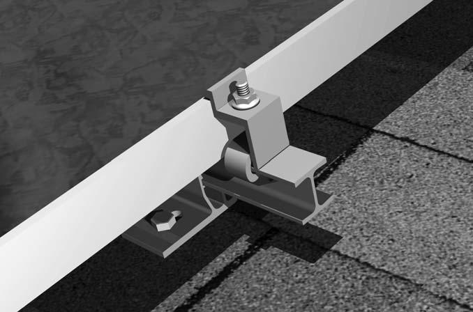
6 INSTALLING CLICKSYS Step 1: Attach beam to 2 Flange Connection or 1 Flange Connection NOTE: Always engage one side before clicking connection into beam. NOTE: Do not use connection if the engagement features on the connection are bent or damaged. Beam Step 2: Attach 2 Flange Connection or 1 Flange Connection to rafter NOTE: When using 2 Flange Connection w/butyl Pad, remove liner before installing screws. Concealor Screw Lag Bolt 2 Flange Connection Option 1 Flange Connection Option

 - Use when splicing two beams at a")

7 Step 3: Install appropriate number of sliders and optional UGC-2 grounding clips Slider UGC-2 (optional) Hex Bolt Step 4A: Install Splices (Option 1) - Use when splicing two beams at a connection NOTE: Tighten nut to 75 inch pounds with anti-seize Splice Bracket WEEB 9.5 (Only with ground splice option) Splice Bar
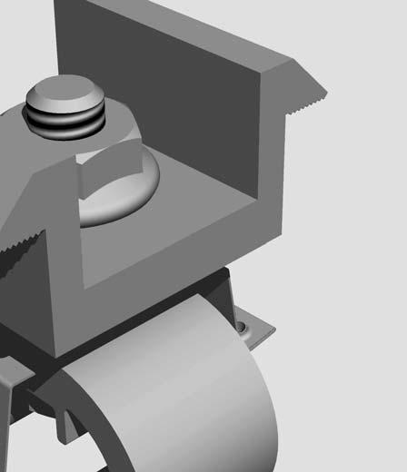
8 Step 4B: Install Retaining Clip (Option 2) - Use as a retaining clip on single beam applications NOTE: Tighten nut to 75 inch pounds with anti-seize. NOTE: Sliders cannot be moved along beam once retaining clip is installed. NOTES ON THERMAL EXPANSION: CLICKSYS is designed to minimize the effects of thermal expansion by allowing the beams to expand and contract independently between connections and attachments. To minimize the effect of thermal expansion, restrict continuous beam lengths to 36 feet or three standard beam lengths. Field Dril Step 5: Installing Grounding Lugs WEEB Lug

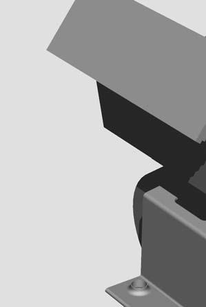
9 Step 6: Attach modules using top mounting hardware NOTE: Tighten nut to 75 inch pounds with anti-seize. End Clamp Mid Clamp Module Module Module
10 WARRANTY 10 year limited Product Warranty Unirac, Inc., warrants to the original purchaser ( Purchaser ) of product(s) that it manufactures ( Product ) at the original installation site that the Product shall be free from defects in material and workmanship for a period of ten (10) years, from the earlier of 1) the date the installation of the Product is completed, or 2) 30 days after the purchase of the Product by the original Purchaser. The Warranty does not apply to any foreign residue deposited on the fi nish. All installations in corrosive atmospheric conditions are excluded. This Warranty does not cover damage to the Product that occurs during its shipment, storage, or installation. This Warranty shall be VOID if installation of the Product is not performed in accordance with Unirac s written installation instructions and design specifi cations therein, or if the Product has been modified, repaired, or reworked in a manner not previously authorized by Unirac IN WRITING, or if the Product is installed in an environment for which it was not designed. Unirac shall not be liable for consequential, contingent or incidental damages arising out of the use of the Product by Purchaser under any circumstances. If within the specified Warranty period the Product shall be reasonably proven to be defective, then Unirac shall repair or replace the defective Product, or any part thereof, in Unirac s sole discretion. Such repair or replacement shall completely satisfy and discharge all of Unirac s liability with respect to this limited Warranty. Under no circumstances shall Unirac be liable for special, indirect or consequential damages arising out of or related to use by Purchaser of the Product. Manufacturers of related items, such as PV modules and fl ashings, may provide written warranties of their own. Unirac s limited Warranty covers only its Product, and not any related items. INSTALLATION MANUAL v
SolarMount-I INSTALLATION MANUAL
 SolarMount-I INSTALLATION MANUAL 2010 by Unirac, Inc. All rights reserved. Pub 100621-1ii, June 2010 R A HILTI GROUP COMPANY 1411 Broadway Boulevard NE Albuquerque, NM 87102-1545 USA IMPORTANT! Unirac
SolarMount-I INSTALLATION MANUAL Broadway Boulevard NE Albuquerque, NM USA A HILTI GROUP COMPANY
 SolarMount-I INSTALLATION MANUAL 2011 by Unirac, Inc. All rights reserved. Pub 110518-1ii, May 2011 A HILTI GROUP COMPANY R 1411 Broadway Boulevard NE Albuquerque, NM 87102-1545 USA IMPORTANT! Unirac Inc.
Unirac Flat Flashing INSTALLATION MANUAL
 Unirac Flat Flashing INSTALLATION MANUAL 2011 by Unirac, Inc. All rights reserved. Pub 110301-1ii, March 2011 A HILTI GROUP COMPANY R 1411 Broadway Boulevard NE Albuquerque, NM 87102-1545 USA IMPORTANT!
SolarMount (E)volution
volution") SolarMount (E)volution SOLARMOUNT (E)VOLUTION: THE BEST JUST GOT BETTER. Engineering, Excellence, and Ease. Performance Engineered for versatility and reduced installation time, SolarMount (E)volution
SolarMount (E)volution SOLARMOUNT (E)VOLUTION: THE BEST JUST GOT BETTER. Engineering, Excellence, and Ease. Performance Engineered for versatility and reduced installation time, SolarMount (E)volution
SunPower Installation Manual
 SunPower SF System Planning and Assembly SunPower SUNPOWER CORPORATION WWW.SUNPOWERCORP.COM Pub #101001-SP2 October 2010 - Rev. 8 2010 by SunPower, Corp All rights reserved. Part I. Scope, components,
Unirac Installation Manual
 Tile Roof Hook Universal Mount Unirac R Pub 090727-1ii June 2009 A HILTI GROUP COMPANY Unirac welcomes input concerning the accuracy and user-friendliness of this publication. Please write to publications@unirac.com.
Mounting Systems. Tilt Kit Installation Guide. Tilt Kit Installation Guide. Table of Contents
 Mounting Systems Tilt Kit Installation Guide Tilt Kit Installation Guide Table of Contents Part I. Preparing.........................................2-4 Part II. Feature of the Rail and the Module...................
orientation Conergy SunTop Instructions for professional installation
 On-roof Framed modules Portrait orientation Landscape Three-tab Shingle Plain tile Slate Double Roman tile Metal roof Material warranty orientation Conergy SunTop Instructions for professional installation
Chiko Flat Pitched roof installation roof installation Guide Gui
 Mounting Systems Tilt Kit Installation Guide Table of Contents Part I. Preparing.. 2-6 Part II. Feature of the Rail and the Module 6-8 Part III. Planning the array laylout... 9 Part IV. Installation instruction.
Single Arm Pole Mount. Installation Manual Edition v1.01. For models: UNI-SA/14 UNI-SA/21.5 UNI-SA/26 UNI-SA01-MAN
 Pole Mount Installation Manual 2016 Edition v1.01 For models: UNI-SA/14 UNI-SA/21.5 UNI-SA/26 UNI-SA01-MAN Table of Contents 1 1 2 3 4 5 5 Introduction Customer Support Project Essentials Assembly: Steps
EzQuikTM. MicroSolar System EzQuik TM Aluminum Solar PV Module Mounting System. Code-Compliant Installation Manual V1011 (AS/NZ1170) Model 2012
 Model 2012") TM Model 2012 Code-Compliant Installation Manual V1011 (AS/NZ1170) MicroSolar System TM Aluminum Solar PV Module Mounting System 1 CONTENTS SECTION 1 INTRODUCTION... 3 1.1... 3 1.2 Why?... 3 1.3 Before
TM Model 2012 Code-Compliant Installation Manual V1011 (AS/NZ1170) MicroSolar System TM Aluminum Solar PV Module Mounting System 1 CONTENTS SECTION 1 INTRODUCTION... 3 1.1... 3 1.2 Why?... 3 1.3 Before
PV-ezRack PostMount 1-A Installation Guide
 PV-ezRack PostMount 1-A Installation Guide NO.: PZ10A -IM06-10 Version:V1.0 Editor: Edit date: Check by: Audit by: Approve by: File record Content Editor Date V1.0 English Bronze 2015.4.17 CONTENT 1. Introduction..
INSTALLATION GUIDE SM SOLAR MOUNT PUB15JAN01
 MOUNT INSTALLATION GUIDE PUB5JAN0 SM SOLAR Wrenches and Torque Wrench Size Recommended Torque (ft-lbs) /4 Hardware 7/6 *0 3/8 Hardware 9/6 *30 # Hardware 5/6 0 Torques are not designed for use with wood
Installation Manual XRL Solar Rail System
 Installation Manual XRL Solar Rail System Solar Mounting Solutions June 2009 www.ironridge.com 2009 IronRidge, Inc. All Rights Reserved Version 1.0 2 XRL Solar Rail System Installation Guide Introduction
Installation Manual Tilt Leg
 Installation Manual Tilt Leg Solar Mounting Solutions March www.ironridge.com 2010 IronRidge, Inc. All Rights Reserved Version 2.0 2 Tilt Leg Installation Guide Introduction The Tilt Leg is a flexible
INSTALLATION GUIDE SM SOLAR MOUNT PUB15JUN15
 MOUNT INSTALLATION GUIDE PUB5JUN5 Wrenches and Torque SM SOLAR Wrench Size Recommended Torque (ft-lbs) /4 Hardware 7/6 *0 3/8 Hardware 9/6 *30 # Hardware 5/6 0 Torques are not designed for use with wood
ROOF MOUNT. *Class A* Fire Rated INSTALLATION MANUAL
 ROOF MOUNT 4008083 *Class A* Fire Rated INSTALLATION MANUAL Contents DISCLAIMER 1 RATINGS 1 CHECKLIST 2 PRIMARY COMPONENTS 3 1. ATTACH BASES 3 2. PLACE RAILS 3 3. SECURE LUG 4 4. CLAMP MODULES 4 EXPANSION
ROOF MOUNT. *Class A* Fire Rated INSTALLATION MANUAL
 ROOF MOUNT 4008083 *Class A* Fire Rated INSTALLATION MANUAL CONTENTS DISCLAIMER 1 RATINGS 1 CHECKLIST 2 PRIMARY COMPONENTS 3 0. ATTACH BASES 3 1. PLACE RAILS 3 2. SECURE LUG 4 3. CLAMP MODULES 4 EXPANSION
PV-ezRack Solar Terrace II-A Installation guide
 PV-ezRack Solar Terrace II-A Installation guide Contents 1 Introduction..2 2 Tools & Components.3 3 System overview.4 4 Installation steps..7 5 Notices and Safety Precautions.. 14 6 Project Case...16 7
MRac Ground Terrace VI Installation Guide (with Ground Screw)
") MRac Ground Terrace VI Installation Guide (with Ground Screw) Content 1 Product Introduction--------------------------------------------------------------------P2 2 Installation Tools & Components-----------------------------------------------------P3
MRac Ground Terrace VI Installation Guide (with Ground Screw) Content 1 Product Introduction--------------------------------------------------------------------P2 2 Installation Tools & Components-----------------------------------------------------P3
MRac Solar Carport System Installation Guide
 MRac Solar Carport System Installation Guide Content 1 Product Introduction ------------------------------------------P2 2 Installation Tool & Components-------------------------------P3 3 Installation
Installation Manual. Tamarack Solar Products. Side of Pole Mount Edition v1.02. For models:
 Mount Installation Manual 2016 Edition v1.02 For models: UNI-SP/01 UNI-SP/01A UNI-SP/01XH UNI-SP/01XX UNI-SP/02 UNI-SP/02A UNI-SP/02X UNI-SP/03 UNI-SP01-MAN Table of Contents 1 Introduction 1 Customer
Installation Manual. Tamarack Solar Products. Top of Pole Mount Edition v1.01. For models:
 Mount Installation Manual 2016 Edition v1.01 For models: UNI-TP/06 UNI-TP/06LL UNI-TP/08 UNI-TP/08LL UNI-TP/10 UNI-TP/10LL UNI-TP/12 UNI-TP/12LL UNI-TP02-MAN Table of Contents 1 Introduction 1 2 Customer
Installation Manual. Side of Pole Mount Edition v3.24. For models:
 Mount Installation Manual 2016 Edition v3.24 For models: UNI-SP/01 UNI-SP/01A UNI-SP/01XH UNI-SP/01XX UNI-SP/02 UNI-SP/02A UNI-SP/02X UNI-SP/03 UNI-SP/03W UNI-SP01-MAN Table of Contents 1 1 2 3 4 5 6 7
Installation Manual. Side of Pole Mount Edition v1.02. For models:
 Side of Pole Mount Installation Manual 2015 Edition v1.02 For models: UNI-SP/01 UNI-SP/01A UNI-SP/01XH UNI-SP/01XX UNI-SP/02 UNI-SP/02A UNI-SP/02X UNI-SP/03 UNI-SP01-MAN Installation Manual Side of Pole
Code-Compliant Planning and Installation Complying with AS/NZS1170.2:2011 ADMT
 PV-ezRack SolarRoof Code-Compliant Planning and Installation Complying with AS/NZS1170.2:2011 ADMT 2-2012 CONTENT 1. Introduction 2 2. Planning. 3 3. Component List 9 4. Array planning.. 10 5. Step by
Installation Instructions
 Installation Instructions HighRock 4x4 TM SlideAway TM Rear Bumper Vehicle Application: 1997-2006 Jeep Wrangler and Wrangler Unlimited HighRock 4x4 TM SlideAway TM Part Number: 42904 www.bestop.com - We
ADJUSTABLE MOUNTING POST
 C Part Number 069 B EACH CARTON CONTAINS D Floor Mounting Kit A. Bottom Post Assembly B. Top Post Assembly C. Flange Head Bolts (x2) D. Floor Mounting Kit. 5/8 Wx/6 Hx0 L framing channels (x2) 2. /8-6x4
Security Products & Services...That Never Sleep. Sur-Lock. I/O 2000L Family of Exit Control Alarm Locks. Installation Instructions
 Security Products & Services...That Never Sleep Sur-Lock I/O 2000L Family of Exit Control Alarm Locks Installation Instructions IMPORTANT It is important that you read and follow these instructions carefully.
SERIES M MIXER MASTS
 SERIES M MIXER MASTS T AB L E O F C O N T E N T S V e n d o r D a t a Material Data Sheet 4-in. Mixer Mast Specification 3-in. Mixer Mast Specification 2 - in. M i x e r M a s t S p e c i f i c a t i o
4Post and 2Post Sliding Rails for Lenovo/IBM M5
 Patent(s) Pending 4Post and 2Post Sliding Rails for Lenovo/IBM M5 4Post Page 2 2Post Center Page 4 Installation Instructions Kit P/N: 122-4818 Kit Contents Kit Contents: (2) (Left & Right) (2) Inner Rail
Installation Instructions Lower Cargo Rack Bracket
 Installation Instructions Lower Cargo Rack Application: Jeep Wrangler 2003 Current Part Number: 41437 US Patent 6799706 www.bestop.com - We re here to help! Visit our web site and click on Ask a Question.
00108/00110 INSTRUCTION MANUAL
 00108/00110 INSTRUCTION MANUAL Removable and Adjustable Mudflap System IMPORTANT! Please Read this Instruction Booklet prior to assembly of your Rock Tamer Kit. IMPORTANT! Exhaust Systems Note: Any modifications
FXL-168 FIXED RACK ASSEMBLY INSTRUCTIONS SALES ORDER #
 ZOMEWORKS FXL-168 FIXED RACK ASSEMBLY INSTRUCTIONS SALES ORDER # 1 1011 Sawmill Road NW, PO Box 25805, Albuquerque, NM 87125 USA (505) 242-5354 / (800) 279-6342 / FAX (505) 243-5187 E-mail: zomework@zomeworks.com
MaxLite LED Self-Driven LiteBars
 Accessories Length: 4, 12, 40 Connector Box Straight Joiner Wire Joiner Mounting Clip Distribution Box Left Joiner Wire Joiner with Plug length: 40 Magnet Bracket Right Joiner End Cap Rotation Bracket
Ventilation System. Installation Manual. Hog Slat Inc. Newton Grove, NC USA March
 Installation Manual 1 Tunnel Door Framing Instructions It is import to make sure the Tunnel Door opening is flat and plumb. A maximum variation of +/- ½ throughout the length of the opening is acceptable.
Sonoma Outdoor Kitchen Pergola. Assembly Instructions
 Sonoma Outdoor Kitchen Pergola Assembly Instructions Introduction Thank you for your purchase from The Outdoor GreatRoom Company. This pergola has been engineered and manufactured in the USA. This user
INSTRUCTION MANUAL. Specifications Mechanical. 1 5/8 to 2 1/16 O.D. (41mm to 52mm)
") 308 Industrial Park Road Starkville, MS 39759 USA Ph: (662) 323-9538 FAX: (662) 323- General Description Model VB-25FM 2-Meter 5 Elements Beam INSTRUCTION MANUAL This antenna is a 5-element, 2-meter beam
308 Industrial Park Road Starkville, MS 39759 USA Ph: (662) 323-9538 FAX: (662) 323- General Description Model VB-25FM 2-Meter 5 Elements Beam INSTRUCTION MANUAL This antenna is a 5-element, 2-meter beam
Stainless Steel Bench Stand
 Installation Manual Stainless Steel Bench Stand Product(s): 29600 29601 51229 2016 by Fairbanks Scales, Inc. Revision 2 02/16 All rights reserved. Amendment Record STAINLESS STEEL BENCH STAND Document
Assembly & Installation Instructions
 Wall Mount Garden Hose Reel Model 1041 Assembly & Installation Instructions 1 2 3 4 5 6 8 9 10 12 15 7 11 10 16 17 13 14 CONTENTS QUESTIONS? PROBLEMS? Please DO NOT contact or return this item to the retailer.
Safety Awareness Barriers
 INSTALLATION INSTRUCTIONS FOR These safety awareness barriers are ideal for use in the manufacturing industry to provide a physical and visual means to warn people that hazards exist beyond the barrier.
EZ Tile Hook System. SunModo PV Rack Mount System UL2703 Compliant
 SunModo PV Rack Mount System UL2703 Compliant Pub. D10007-V005 Copyright 2016 Please read carefully before installing Product is tested to and recognized to UL 2703 standards for safety grounding and bonding
4" Oval Nerf Bar. Part No. A1007S/B. PARTS LIST: Qty Part Description Qty Part Description
 4" Oval Nerf Bar Part No. A1007S/B Fits: 2009 - Current Dodge Ram 1500 Crew Cab 2001 - Current Dodge Ram 2500/3500 Crew Cab REMOVE CONTENTS FROM BOX. VERIFY ALL PARTS ARE PRESENT. 60-180 min Cutting Not
Box Edge Plus Steel Shelving Installation Instructions
 Box Edge Plus Steel Shelving Installation Instructions IMPORTANT PRODUCT LIABILITY INFORMATION Read all instructions before proceeding with installation or shelf loading. Vital product information pertaining
25-A Shawnee Way Bozeman, MT Fed ID PH FAX
 25-A Shawnee Way Bozeman, MT 59715 Fed ID 81-0414516 PH 406-586-9393 FAX 406-585-7378 SkyBar Mount for UTV with 1 ¾ 2 Roll Bar Standard Mount (optional mount on page 3) This gun rack is supplied with brackets
Installation and Assembly: Articulating Swivel Arm for 37" - 60" Flat Panel Displays
 Installation and Assembly: Articulating Swivel Arm for 37" - 60" Flat Panel Displays Models: PLA60, PLA60-S, PLAV60, PLAV60-S Max UL Load Capacity: 175 lb (79 kg) 2300 White Oak Circle Aurora, Il 60502
Pole Mount Installation Manual
 Pole Mount Installation Manual Thank You for Choosing AIMS Power! 1. AIMS Power is a leading supplier of solar products, specializing in PV mounting systems. We ensure our products are manufactured to
Assembly & Installation Instructions
 Wall Mount Hose Reel Model 04-GH Configuration Pulls the hose out straight away from the wall. Configuration Pulls the hose out along side the wall. Assembly & Installation Instructions Version 0409 A
Installation Instructions for Solar Snow Pad (SSP-T-3)
") Installation Instructions for Solar Snow Pad (SSP-T-3) Warning- Do not use this product on solar arrays where the calculated array snow loads exceed 50 pounds per square foot (psf). Most solar panels are
Installation Instructions for Solar Snow Pad (SSP-T-3) Warning- Do not use this product on solar arrays where the calculated array snow loads exceed 50 pounds per square foot (psf). Most solar panels are
INSTALLATION INSTRUCTIONS
 INSTALLATION INSTRUCTIONS Premier Mounts Tilting Wall Mount Model: TWM-085 For use with Panasonic 85 Flat Panel NORTH AMERICA 3130 East Miraloma Avenue Anaheim, CA 92806 USA USA and Canada Phone: 1.800.368.9700
LJ element beam for 10 or 12 meters INSTRUCTION MANUAL. CAUTION: Read All Instructions Before Operating Equipment
 LJ-113 3 element beam for 10 or 1 meters INSTRUCTION MANUAL CAUTION: Read All Instructions Before Operating Equipment 308 Industrial Park Road Starkville, MS 39759 USA Tel: 66-33-9538 Fax: 66-33-6551 VERSION
SOLAR ROOF MOUNTING SYSTEM INSTALLATION MANUAL Model Name TT-ADJUSTABLE TILT LEGS
 SOLAR ROOF MOUNTING SYSTEM INSTALLATION MANUAL Model Name TT-ADJUSTABLE TILT LEGS JIANGYIN TITANERGY CO.,LTD Contents Chapter Title Page 1 General Information 3 2 Safety and Installer Responsibilities
Wenger Corporation 2010 Printed in China 02/10 Part #148H Wenger Corporation, 555 Park Drive, P.O. Box 448, Owatonna, Minnesota
 Assembly Instructions Violin/Viola Storage Rack CONTENTS Safety Precautions.................................. Warranty.......................................... Important User Information............................
Installation Instructions
 Installation Instructions Sure Step (Part # DN260-S4B/ DN260-S4S Part # DN270-S4B/ DN270-S4S) 2009-2010 Dodge Ram1500 Crew Cab & Quad Cab 2010 Ram 2500/3500 Crew Cab For Technical Support/Warranty Information
4Post and 2Post Rails for Dell PowerEdge R810
 4Post and 2Post Rails for Dell PowerEdge R810 Patent(s) Pending 4Post Page 2 2Post Center Page 4 2Post Flush Page 6 Installation Instructions Kit P/N: 109-1737 109-1841 Kit Contents Kit Contents: (1) Right
Installation Instructions HOSS Hardtop Organized Storage System
 Installation Instructions HOSS Hardtop Organized Storage System Application: Hard Top and Doors Storage System Part Number: 42801 www.bestop.com - We re here to help! Visit our web site and click on Ask
Model VB-23FM 2-Meter 3-Element Beam
 308 Industrial Park Road Starkville, MS 39759 USA Ph: (662) 323-9538 FAX: (662) Model VB-23FM 2-Meter 3-Element Beam [ INSTRUCTION MANUAL Figure 1 Overall View and Boom Detail GENERAL DESCRIPTION This
Installation Instructions Tailgate Rack Bracket
 Installation Instructions Tailgate Rack Application: Jeep Wrangler 1986 Current Part Number: 41411 www.bestop.com - We re here to help! Visit our web site and click on Ask a Question. Click here for more
Owner s Manual & Safety Instructions
 Owner s Manual & Safety Instructions Save This Manual Keep this manual for the safety warnings and precautions, assembly, operating, inspection, maintenance and cleaning procedures. Write the product s
PATRIOT DOCKS ASSEMBLY INSTRUCTIONS
 6/1/2008 PATRIOT DOCKS ASSEMBLY INSTRUCTIONS Congratulations on your new Patriot Dock purchase. This manual contains instructions to assemble basic dock configurations for use at typical shoreline application.
Access Hatch. Installation Instructions and Operators Manual. PS DOORS Contact Information. Model AH-710 Standard High Neck Radius Cut
 Access Hatch Installation Instructions and Operators Manual Standard Low Profile Frame Model AH-710 Standard High Neck Radius Cut High Neck Frame for special applications. Table of Contents Warranty Information...2
Flush Mount. SunEarth Flush Mount Installation Manual. SunEarth Flush Mount. Asphalt Shingle Roofing
 Flush Mount SunEarth Flush Mount Installation Manual Thank you for choosing the SunEarth flush mount method. It provides a strong durable solution for mounting SunEarth collectors parallel to the roof
Rayport G Eco Dealer Kit
 Rayport G Eco Dealer Kit Installation Guide www.aetenergy.com Supporting a Cleaner, Greener Tomorrow 1. Table of Contents 1. Table of Contents P2 2. Installer Notes P3 3. Parts List P4-7 4. Tool List P8
INSTALLATION INSTRUCTIONS
 INSTALLATION INSTRUCTIONS P4263F Universal Low Profi le Flat Mount for 42 to 63 Flat Panels NORTH AMERICA 3130 East Miraloma Avenue Anaheim, CA 92806 USA USA and Canada Phone: 1.800.368.9700 Fax: 1.800.832.4888
Lodge II Pergola. Manual and Installation Instructions. Please read these instructions before removing parts from crate
 Lodge II Pergola Manual and Installation Instructions Please read these instructions before removing parts from crate Introduction Thank you for your purchase from The Outdoor GreatRoom Company. This pergola
Installation and Assembly: Recessed Cable Management and Power Storage Accessory Box
 Installation and Assembly: Recessed Cable Management and Power Storage Accessory Box Models: IBA3, IBA3-W 2300 White Oak Circle Aurora, Il 60502 (800) 865-2112 Fax: (800) 359-6500 www.peerlessmounts.com
XIAMEN FENGWEI ENERGY TECHNOLOGY CO., LTD. GRACE SOLAR ROOF MOUNTING SYSTEM INSTALLATION Manual
 XIAMEN FENGWEI ENERGY TECHNOLOGY CO., LTD. GRACE SOLAR ROOF MOUNTING SYSTEM INSTALLATION Manual Contents Chapter Title Page 1 General information 3 2 Safety and Installer Responsibilities 4 3 Technical
Installation & Assembly: Two Piece Suspended Ceiling Plate
 Installation & ssembly: Two Piece Suspended Ceiling Plate Model: CMJ453 Max UL Load Capacity: 250 lb (113 kg) Compatible model/series* EC* EXT* DD* 2300 White Oak Circle urora, Il 60502 (800) 865-2112
FRYCORDER Power Cord Burn-in Generator
 FRYCORDER Power Cord Burn-in Generator Made in USA FRYCORDER Power Cord Burn-in Generator Copyrights & Trademarks Copyright Hagerman Audio Labs 0. All rights reserved. No part of this document may be photocopied,
1 of 6 SITE PLAN MW. Sample GAMECHANGE SOLAR. Sample. Sample AERIAL VIEW. Array Information. Design Information. Racking.
 AERIAL VIEW Array Information PV Modules Racking Manufacturer NEO Solar Gamechange Racking Model D6M-B4A 23-Degree MaxSpan Dimensions Weight 77.0"x39.1"x1.57" 56.2 lbs Quantity 5184 407 Ground learance
ASSEMBLY INSTRUCTIONS Last Updated
 ASSEMBLY INSTRUCTIONS Last Updated 05.08.08 5 & 10 Row Bleacher Instructions for all bleacher lengths. Guardrail and toe board installation included. 90653 9 Long 5 Row Bleacher 90654 15 Long 5 Row Bleacher
SHEET METAL MACHINES, INC. SAFETY & INSTRUCTION MANUAL FOR MODEL N12016 BRAKE MADE IN USA
 NATIONAL SHEET METAL MACHINES, INC. SAFETY & INSTRUCTION MANUAL FOR MODEL N12016 BRAKE MADE IN USA CONTENTS For Safe and Efficient Operation.... 1 Safe Zone.. 2 Parts Lists... 3-4 Machine Dimensions...
60 Meter Mono-Band Conversion Kit for the DXE-MBVE-5A Multi-Band Vertical Antenna
 60 Meter Mono-Band Conversion Kit for the DXE-MBVE-5A Multi-Band Vertical Antenna DXE-MBVE-5A60MCK DXE-MBVE-5A60MCK-INS Revision 0a DX Engineering 2017 1200 Southeast Ave. - Tallmadge, OH 44278 USA Phone:
GEARGRID Seattle / SCUBA Storage System
 GEARGRID Seattle / SCUBA Storage System Assembly Instructions & Owners Manual Thank you for choosing the Geargrid Seattle / SCUBA Storage System. Geargrid is committed to high-quality products and your
Agilent N2902A 9000 Series Oscilloscope Rack Mount Kit
 Agilent N2902A 9000 Series Oscilloscope Rack Mount Kit Installation Guide Agilent Technologies Notices Agilent Technologies, Inc. 2009 No part of this manual may be reproduced in any form or by any means
Guitar Mobile Storage Rack
 Assembly Instructions Guitar Mobile Storage Rack CONTENTS Safety Precautions.................................. 2 Warranty.......................................... 2 Operation.........................................
Sonoma 1216 Pergola Manual and Installation Instructions. Please read these instructions before removing parts from crate
 Sonoma 1216 Pergola Manual and Installation Instructions Please read these instructions before removing parts from crate Introduction Thank you for your purchase from The Outdoor Greatoom Company. This
FENDER FLARE. KIT CONTAINS Qty Part Description Qty Part Description
 ` FENDER FLARE Part No: FFC3002S TO AVOID BEING SCRATCHED, PLEASE PROTECT THE SURFACE OF THE FENDER FLARE CAREFULLY. REMOVE CONTENTS FROM BOX. VERIFY ALL PARTS ARE PRESENT. 60-180 min Cutting Not Required
CURATED CARTESIAN VANITY
 CURATED CARTESIAN VANITY CONTENT Prep the wall - 3 Frame installation - 5 Attaching the side kits - 7 Installing any optional vanity accessories - 7 Sink assembly - 8 Insert the drawer - 10 Attaching glass
1 of 9 SITE PLAN modules at 325W kw. Sample GAMECHANGE SOLAR. Sample. Sample AERIAL VIEW. Array Information. Design Information.
 AERIAL VIEW Array Information PV Modules Racking Manufacturer Hyundai Gamechange Racking Model HiS-S325TI 5-Degree GC Grid-Lite Dimensions." x 39.29" x.9" Weight 5. lbs Quantity 224 224 modules at 325W
Installation & Assembly: Suspended Ceiling Kit
 Installation & ssembly: Suspended Ceiling Kit Model: CMJ450 Max UL Load Capacity: 250 lb (113 kg) Compatible model/series* EC* EXT* DD* 2300 White Oak Circle urora, Il 60502 (800) 865-2112 Fax: (800) 359-6500
Standard Rail Roof Mounting System Design Manual
 Standard Rail Roof Mounting System Design Manual Standard Rail (XRS) Splice Addendum... 2 Standard Rail (XRS) Flush Span Chart... 4 Standard Rail (XRS) Tilt Span Chart... 5 IronRidge Roof Mount Attachment
WORLD-BEAM QS18AFF200 Sensors with Foreground Suppression
 WORLD-BEAM QS8AFF00 Sensors with Foreground Suppression Datasheet Compact sensors featuring extended range and foreground suppression mode Exceptional optical performance; up to 00 mm sensing range in
Single Flex and Double Flex Couplings (i)
") Single Flex and Double Flex Couplings (i) FORM NO. L00G00 In accordance with Nexen s established policy of constant product improvement, the specifications contained in this manual are subject to change
Single Flex and Double Flex Couplings (i) FORM NO. L00G00 In accordance with Nexen s established policy of constant product improvement, the specifications contained in this manual are subject to change
Magnum low voltage drawout circuit breaker IEC horizontal stab cassette shutter kit (double wide A cassettes)
") kit (double wide 4000 6300A cassettes) i WARNING (1) ONLY QUALIFIED ELECTRICAL PERSONNEL SHOULD BE PERMITTED TO WORK ON THE EQUIPMENT. (2) ALWAYS DE-ENERGIZE PRIMARY AND SECONDARY CIRCUITS IF A CIRCUIT
kit (double wide 4000 6300A cassettes) i WARNING (1) ONLY QUALIFIED ELECTRICAL PERSONNEL SHOULD BE PERMITTED TO WORK ON THE EQUIPMENT. (2) ALWAYS DE-ENERGIZE PRIMARY AND SECONDARY CIRCUITS IF A CIRCUIT
Installation Instructions/Operation and Maintenance Manual. PS DOORS Contact Information. Website psdoors.com
 Ladder Safety Gate Installation Instructions/Operation and Maintenance Manual Models All Models: LSG-5 to LSG-48 Table of Contents Product Information...2 Inspection & Mainteance...2 Warranty Information...2
SHRINKER/STRETCHER SET Create radius bends and contours in sheet metal
 Owner s Manual & Safety Instructions Save This Manual Keep this manual for the safety warnings and precautions, assembly, operating, inspection, maintenance and cleaning procedures. Write the product s
Installation and Assembly: Recessed Cable Management and Power Storage Accessory Box
 Installation and Assembly: Recessed Cable Management and Power Storage Accessory Box Models: IBA2AC, IBA2AC-W 2300 White Oak Circle Aurora, Il 60502 (800) 865-2112 Fax: (800) 359-6500 www.peerlessmounts.com
ALUMA-VENT AWNING REGULAR END STYLE INSTALLATION INSTRUCTIONS
 ALUMA-VENT AWNING REGULAR END STYLE INSTALLATION INSTRUCTIONS Contact us at: 1-888-442-2928 or www.americana.com Options in your kit: A. Splice Pg 16 B. Column Pg 17 C. C-Channel Brace Pg 19 D. Runner
INSTALLATION INSTRUCTIONS FOR FRONT CASTING DECK RAIL Ranger
 INSTALLATION INSTRUCTIONS FOR FRONT CASTING DECK RAIL Ranger TOOLS REQUIRED FOR INSTALLATION: Drill motor, (1) 5/16 inch drill bit, (1) 13/64 drill bit, (1) 3/16 inch hex wrench (1) 3/32 inch hex wrench.
Flexi-Rail Solar Module Mounting System. Flexi Rail. Installation Manual
 Flexi-Rail Solar Module Mounting System Flexi Rail Installation Manual Contents Introduction...3 Installer s Responsibilities...4 Maximum Roof Fix Spacing...5 Flexi Rail Components...6 Roof Fixing Kits...7-11
Caliper Brake WINDCAL 90
 Caliper Brake WINDCAL 90 (i) FORM NO. L-20233-A-0601 In accordance with Nexen s established policy of constant product improvement, the specifications contained in this manual are subject to change without
Record the serial number and date of purchase in your manual for future reference.
 10 Woodworking Bandsaw Model: 10-305 Parts List Record the serial number and date of purchase in your manual for future reference. Serial number: Date of purchase: Part # 10-305PL1 For more information:
Disc Caliper Brake Model DBSE
 AIR CHAMP PRODUCTS User Manual Disc Caliper Brake Model DBSE i In accordance with Nexen s established policy of constant product improvement, the specifications contained in this manual are subject to
SWH Solar Racking Installation Guide
 SOLAR WAREHOUSE SWH Solar Racking Installation Guide Version 16.08.v1 9628 Valley Blvd. Rosemead, CA 91770 INSTALLATION Phone 626-579-3288 GUIDE VERSION info@esolarwarehouse.com - 16.08.V1 SOLAR WAREHOUS
Hopper and Drive Components
 Western Products, PO Box 245038, Milwaukee, WI 53224-9538 www.westernplows.com September 1, 2015 Lit. No. 43772, Rev. 00 Hopper and Drive Components PRO-FLO 525 Low-Profile Tailgate Spreader Parts List
INSTRUCTION MANUAL. Model 18AVQII Five Band Vertical Antenna 10, 15, 20, 40, 80 Meter. General Description. Theory of Operation
 Model 18AVQII Five Band Vertical Antenna 10, 15, 20, 40, 80 Meter 308 Industrial Park Road Starkville, MS 39759 (662) 323-9538 Fax: (662) 323-5803 INSTRUCTION MANUAL General Description The Hy-Gain 18AVQII
Installation Instructions Hustler Collinear Two Meter Fixed Station Antenna Master Gainer Model G6-144B
 Installation Instructions Hustler Collinear Two Meter Fixed Station Antenna Master Gainer Model Warning INSTALLATION OF THIS PRODUCT NEAR POWER LINES IS DANGEROUS. FOR YOUR SAFETY, FOLLOW THE INSTALLATION
May 14, Installation Manual
 May 14, 2012 Installation Manual Contents MAG TRACKER Components...1 Mount Installation...7 Module Installation & Grounding...11 Maintenance...14 Warranty......14 Contact Information......14 May 14, 2012
Grounding and Utility Enclosure
 Grounding and Utility Enclosure UE-1P UE-1P-INS Revision 1 DX Engineering 2006 P.O. Box 1491 Akron, OH 44309-1491 Phone: (800) 777-0703 Tech Support and International: (330) 572-3200 Fax: (330) 572-3279