A LAMP STORY... from Form Finding to Assembly ANNE-MARIE DESMEULES YU-CHANG GRACE LIN REENA MISTRY DAN GUENTER JESSICA SIN RICO LAW THE PORTFOLIO
|
|
|
- Norah Russell
- 5 years ago
- Views:
Transcription


1 THE PORTFOLIO ANNE-MARIE DESMEULES YU-CHANG GRACE LIN REENA MISTRY DAN GUENTER JESSICA SIN RICO LAW A LAMP STORY... from Form Finding to Assembly


2 A) Form-Finding 1.The initial form was based on a broad, open basket. After experimenting the form, we oriented our interested towards the possibility of creating a taller, more slender basket, which would function better as a vase 2.Considering the function was flexible, we continued to experiment with the form to create a shape that could be modified in grasshopper. 3.The scripting was organized to leave variables for form-finding at the beginning so alterations could easily be made. 4.The initial form, with the tilted top circle, had geometry issues. This is evident when looking at the lines formed by the script preview.

3 A) Form-Finding 5.The tilt of the top circle was thus set to zero, to keep the geometry clean and neat. 6.After building the prototype from this form, we decided to adjust the form to meet the new function of a pendant lamp.

4 A) Form-Finding 7.Changing the parameters accoridng to : a.number of divisions b. Top radius c. Base radius d. Height e. Shift


5 B) In Grasshopper 8.We used the tutorial we did in class as the basic idea of the grasshopper script. We wanted to keep the amount of objects drawn in Rhino to an absolute minimum so we could use the variables in our grasshopper script to form-find. Also, in our previous assignment, we had confused two of our Rhino files so we ended up baking on a surface that was too small a 30 x 30 square centimeters instead of the 40 x 40 square centimeters, which resulted in a very dense grid that was too small and harder to construct. (We didn t want to make that mistake again!) Once we picked a form, we started to resolve the thickness of the strips and the holes for the connections. 9.We proceeded finding the tangent vector to the points on the curves. To find the tangent vectors to the points of the circle, a line was first drawn from each of the points to the center of the circle and then rotated 90 degrees. Then the line was scaled and mirrored on both sides of the point.


6 B) In Grasshopper 10.After this was done on the base and top circles, a script was created to loft the lines together with the twist number included. 11.There were attempts to have a series loft all the strips at once, but the twist and shifted sequence of numbers proved to be too much a challenge and so the lofting script was instead repeated for each line. 12.A similar script was then replicated to create the strips running in the opposite direction to the initial script.

, but it only resolved a set of")


7 B) In Grasshopper 13.Holes and points of intersection Points of Intersection: We assumed the curve intersect tool would work (CCX), but it only resolved a set of points, but not all of them. We baked and found that the geometry was warped because of the tilt of the top circle, so to make things simpler, we changed the tilt to zero radians (making the circle flat again, no tilt) and the function worked fine.
.")
8 B) In Grasshopper 14.Holes We first tried to use the lofted surfaces (refer to Jessica s script) to provide the surface upon which we should apply the points of intersection for the holes. This proved to be too complex once we realized the order that the points were generated in (once flattened). This would require an inefficient and tedious script that would take a lot of time in order to coordinate the points to the correct lofted surface. This would also cause troubles when we played more with the form to determine the final shape. So we decided to sweep the surface using the top and bottom circles as the two rails and one line as the section curve. Though we had used the grasshopper sweep2 command (the variables had plugged in fine and no errors showed), there was no result previewed on the screen. So instead, we had to do the same command in Rhino (which worked fine). This is the surface that we set into the Grasshopper function surface seen in the working script here: We then connected the data to the points to the surface and made extruded holes similar to our method used in the previous assignment. Also, to save time, we used the split command in Rhino to cut the holes in the strips instead of using the trim command in Grasshopper.


9 B) In Grasshopper 15.Offsets We were originally going to copy the first script and change the radius of the circles to correlate with the thickness of a sheet of veneer. This script was obviously repetitive and would be tedious if something in the original script changed. Instead, we used a simpler offset method like our previous assignment and clearly labeled it for the team members, who would now take the file to bake.

10 B) In Grasshopper 16.Instead, we used a simpler offset method like our previous assignment and clearly labeled it for the team members, who would now take the file to bake.


11 C) In Rhino The problem we had with the tilted form in the Grasshopper script made us decided to cut the baked form in Rhino to obtain the tilt effect. The cutting plane was defined in the script, so we only had to cut the strips with this inclined ellipse. After, we subtracted the holes makers (which are tubes form the grasshopper script) to the baked strips. The form was then ready to be unroll.


12 D) Respecting Budget We knew the number of veneer panel needed once we placed the pieces of strips in the AutoCad layout. From our initial mock up, we learned that the original form used more veneer panels than we can really afford. The initial estimation for the connections amounted to approximately 20$-30$, hence we hoped to limit our veneer sheets to 3 or 4. Hence, we reduced the thickness of the strips and the size of the model. As a result, we were able to fit everything into 2 sheets of veneers, which totalize 24$ in material. At the end, we used a total of: -5$ for the mock up for connections -15$ for the final connections -2 sheets for the mock up and 2 sheets for the final at 48$ -10$ for the light bulb and light fixture Our final pricing for the fabrication the product was: 24$ + 15$ + 10$ = 49$ This was under the 70$ budget!


13 E) Learning from Mockup Making a mock up was critical in our process to stay UNDER budget. By only constructing 20% of our initial design, we realized that we were way over budget, as we were using already 2 sheets of veneers. Testing in our mock up, we had cut the strips along and against the direction of the grain. The strips were stronger as we cut along the grain of the veneers. During the construction of the mock up, we tested with nut and bolts. We preferred the aesthetic of the connections. However, we were aware of the difficulty of assembly, as they needed to be bolted inside the lamp. Assembly was predicted to be tedious and difficult, but we had some able hands on board the team. Laser cutting was problematic. Since the veneer sheets warped and pieces cut would move.


14 F) Bake & Unroll In the unrolling process in Rhino, the strips were flipped. Hence the surface facing the exterior of the lamp was flipped inward and vice versa. This was unannounced to us, as we proceeded with assembly. As a consequence, the bottom edge is not straight across. However, we were quite satisfied with the aesthetic results.


15 G) Laser Cutting We wanted to find an aesthetic way for numbering our strips. Since ithey do appear on the exterior layer of the lamp, we wanted symbols that would dictate the number of the layers, the direction of the strips and the order of the strips. The strips were along the longitudinal direction of the lamp, they were laid out in the same way on the panel. The strips were laid down along the grain of the veneer for strength. From our initial experience laser cutting the mock up, we noticed that the veneer sheets were warped. As a result, the pieces cut would move while the machine was cutting To prevent problems, we assigned the colors in laser cutter so that the holes were cut first, then the long edges of the strips, then the shorter edges. Also the veneer sheets were mounted on a MDF board with double sided tape.


16 H) Assembly A precise and detailed transfer of information and process is important in the project. It is difficult to relate the cut pieces with the initial model. In addition, an organization of the pieces and precise planning before assembly is eminent. The building process was tedious, as the double sided tape needed to be removed. Also, the smaller lamp meant that it was more difficult to tighten the bolts in the interior of the lamp. Having the right tools is essential in assembly such an object. Another issue was the size of the holes, which were too small. Hence, we had to enlarge them before assembly. Many skilled hands were needed at once to hold and bolt at the same time.


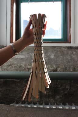


17 H) Assembly Building Final product


18 H. Final Result Final Product
MODELING AND DESIGN C H A P T E R F O U R
 MODELING AND DESIGN C H A P T E R F O U R OBJECTIVES 1. Identify and specify basic geometric elements and primitive shapes. 2. Select a 2D profile that best describes the shape of an object. 3. Identify
SolidWorks 95 User s Guide
 SolidWorks 95 User s Guide Disclaimer: The following User Guide was extracted from SolidWorks 95 Help files and was not originally distributed in this format. All content 1995, SolidWorks Corporation Contents
Advanced Modeling Techniques Sweep and Helical Sweep
 Advanced Modeling Techniques Sweep and Helical Sweep Sweep A sweep is a profile that follows a path placed on a datum. It is important when creating a sweep that the designer plans the size of the path
8 Working Drawings in AutoCAD
 8 Working Drawings in AutoCAD Most engineering designs consist of more than a single part. Usually there are a several or many parts that must fit and work together. When we are creating the drawings of
Introduction to Sheet Metal Features SolidWorks 2009
 SolidWorks 2009 Table of Contents Introduction to Sheet Metal Features Base Flange Method Magazine File.. 3 Envelopment & Development of Surfaces.. 14 Development of Transition Pieces.. 23 Conversion to
Drawing and Assembling
 Youth Explore Trades Skills Description In this activity the six sides of a die will be drawn and then assembled together. The intent is to understand how constraints are used to lock individual parts
Isometric Drawings. Figure A 1
 A Isometric Drawings ISOMETRIC BASICS Isometric drawings are a means of drawing an object in picture form for better clarifying the object s appearance. These types of drawings resemble a picture of an
Datum Tutorial Part: Cutter
 Datum Tutorial Part: Cutter Objective: Learn to apply Datums in different ways Directions 1. Datum Axis Creation a. First we need to create a center axis for the cutter b. Model Tab > Datum > Select Axis
Inventor Activity 5: Lofted Vase
 Inventor Activity 5: Lofted Vase In this tutorial, you will use a few new commands to create a free form Lofted object. Sometimes you want to create an object that is not made up of square, flat, or perfectly
Advance Steel. Tutorial
 Advance Steel Tutorial Table of contents About this tutorial... 7 How to use this guide...9 Lesson 1: Creating a building grid...10 Step 1: Creating an axis group in the X direction...10 Step 2: Creating
From the above fig. After sketching the path and profile select the sweep command First select the profile from property manager tree And then select
 Chapter 5 In sweep command there is a) Two sketch profiles b) Two path c) One sketch profile and one path The sweep profile is used to create threads springs circular things and difficult geometry. For
LABORATORY MANUAL COMPUTER AIDED DESIGN LAB
 LABORATORY MANUAL COMPUTER AIDED DESIGN LAB Sr. No 1 2 3 Experiment Title Setting up of drawing environment by setting drawing limits, drawing units, naming the drawing, naming layers, setting line types
Spatula. Spatula SW 2015 Design & Communication Graphics Page 1
 Spatula Introduction: The model shown in the picture is made of three parts, - the base, the washer and the handle. The base requires the use of Spline and Style Spline command, Slot command and Mirror
Alternatively, the solid section can be made with open line sketch and adding thickness by Thicken Sketch.
 Sketcher All feature creation begins with two-dimensional drawing in the sketcher and then adding the third dimension in some way. The sketcher has many menus to help create various types of sketches.
Projects. 5 For each component, produce a drawing showing the intersection BO.O. C'BORE 18 DIA x 5 DEEP FROM SECTION ON A - A
 Projects ~ Figure Pl Project 1 If you have worked systematically through the assignments in this workbook, you should now be able to tackle the following milling and turning projects. It is suggested that
SolidWorks Reference Geometry
 SolidWorks Reference Geometry IDeATe Laser Micro Part 2 Dave Touretzky and Susan Finger 1. Symmetry and Reference Geometry Today, you ll make this part bear-like face and then cut it on the laser cutter:
Introduction to Autodesk Inventor User Interface Student Manual MODEL WINDOW
 Emmett Wemp EDTECH 503 Introduction to Autodesk Inventor User Interface Fill in the blanks of the different tools available in the user interface of Autodesk Inventor as your instructor discusses them.
Engineering & Computer Graphics Workbook Using SolidWorks 2014
 Engineering & Computer Graphics Workbook Using SolidWorks 2014 Ronald E. Barr Thomas J. Krueger Davor Juricic SDC PUBLICATIONS Better Textbooks. Lower Prices. www.sdcpublications.com Powered by TCPDF (www.tcpdf.org)
Rhino 3D - Digital Crafting Tutorial instructions for simple shape fabrication. Waffle
 Rhino 3D - Digital Crafting Tutorial instructions for simple shape fabrication Waffle Manuel Kretzer 2016 1. Draw or import your geometry into the Rhino workspace. 2. Create and select a new layer or rename
AutoCAD Tutor 2011 Support Docs
 AutoCAD Tutor 2011 Support Docs CHAPTER 1 CUSTOMIZING THE QUICK ACCESS TOOLBAR One of the advantages of the Quick Access Toolbar is the ability to display the AutoCAD commands that you frequently use.
Unit 4: Geometric Construction (Chapter4: Geometry For Modeling and Design)
") Unit 4: Geometric Construction (Chapter4: Geometry For Modeling and Design) DFTG-1305 Technical Drafting Instructor: Jimmy Nhan OBJECTIVES 1. Identify and specify basic geometric elements and primitive
Unit 4: Geometric Construction (Chapter4: Geometry For Modeling and Design) DFTG-1305 Technical Drafting Instructor: Jimmy Nhan OBJECTIVES 1. Identify and specify basic geometric elements and primitive
ARCH 332: BUILDING SHOP II VAULTING SPACE: TOOLS & TECHNOLOGIES
 GOTHIC DIGITAL VAULTING PROJECT: THE VOUSSOIR SUBJECT: Now that you know how to find the dimensions of a voussoir geometrically and algebraically, we can move to 3D modelling. Based on the information
S206E Lecture 6, 5/18/2016, Rhino 3D Architectural Modeling an overview
 Copyright 2016, Chiu-Shui Chan. All Rights Reserved. S206E057 Spring 2016 This tutorial is to introduce a basic understanding on how to apply visual projection techniques of generating a 3D model based
Using the Laser Cutter and Rhino Template
 1 Using the Laser Cutter and Rhino Template This tutorial outlines the best way to cut and etch using the laser cutter. Your project is important to you, and you want to finish it efficiently. Using this
PLTW IED MID TERM EXAM REVIEW Part A Multiple Choice
 2014-15 PLTW IED MID TERM EXAM REVIEW Part A Multiple Choice Directions: Select the letter of the response which best completes the item or answers the question. Then record your answer on the answer sheet
Beginner s Guide to SolidWorks Level I
 Beginner s Guide to SolidWorks 2013 - Level I Parts, Assemblies, Drawings, Simulation Xpress Alejandro Reyes MSME, CSWP, CSWI SDC PUBLICATIONS Schroff Development Corporation Better Textbooks. Lower Prices.
Learning Guide. ASR Automated Systems Research Inc. # Douglas Crescent, Langley, BC. V3A 4B6. Fax:
 Learning Guide ASR Automated Systems Research Inc. #1 20461 Douglas Crescent, Langley, BC. V3A 4B6 Toll free: 1-800-818-2051 e-mail: support@asrsoft.com Fax: 604-539-1334 www.asrsoft.com Copyright 1991-2013
Creo Revolve Tutorial
 Creo Revolve Tutorial Setup 1. Open Creo Parametric Note: Refer back to the Creo Extrude Tutorial for references and screen shots of the Creo layout 2. Set Working Directory a. From the Model Tree navigate
Chapter 7 Isometric Drawings
 Chapter 7 Isometric Drawings In this assignment, we are going to look at creating isometric drawings with AutoCAD. These drawing appear to be three dimensional but they are not. An AutoCAD isometric drawing
Engineering & Computer Graphics Workbook Using SOLIDWORKS
 Engineering & Computer Graphics Workbook Using SOLIDWORKS 2017 Ronald E. Barr Thomas J. Krueger Davor Juricic SDC PUBLICATIONS Better Textbooks. Lower Prices. www.sdcpublications.com Powered by TCPDF (www.tcpdf.org)
Descriptive Geometry CH17 : DEVELOPMENTS
 Descriptive Geometry CH17 : DEVELOPMENTS Developments A development is a flat representation or pattern that when folded together creates a 3D object. Developable Surfaces A developable surface may be
CAD Tutorial 24: Step by Step Guide
 CAD TUTORIAL 24: Step by step CAD Tutorial 24: Step by Step Guide Level of Difficulty Time Approximately 40 50 minutes Lesson Objectives To understand the basic tools used in SketchUp. To understand the
Module 1H: Creating an Ellipse-Based Cylindrical Sheet-metal Lateral Piece
 Inventor (10) Module 1H: 1H- 1 Module 1H: Creating an Ellipse-Based Cylindrical Sheet-metal Lateral Piece In this Module, we will learn how to create an ellipse-based cylindrical sheetmetal lateral piece
LABORATORY MANUAL COMPUTER AIDED DESIGN LAB ME-211-F
 LABORATORY MANUAL COMPUTER AIDED DESIGN LAB ME-211-F List of Experiments:- Sl. No. Name of experiment Date Signature 01 02 Setting up of drawing environment by setting drawing limits, drawing units, naming
designed a system for producing multiple and endlessly variable forms of lights Form Twist Segments
 The submitted project is a forward thinking lighting design concept that fully engages contemporary means of digital design and production creating mass-customized fixtures efficiently and economically.
Introducing SolidWorks
 Introducing SolidWorks SAAST Robotics 2008 SolidWorks Software Visually-based 3-D Mechanical design software Engineers and Designers use it to: Quickly sketch out ideas Experiment with features, dimensions
CAD & BSI Theory. Arbroath Academy - Technology Department - National 5 Graphic Communication
 CAD & BSI Theory These symbols are drawn from BSI. Building Drawing Symbols You may be required to use these symbols in your assignment or project, or be asked questions about them in your exam. You must
CAD tutorial for the drinking straw support
 CAD tutorial for the drinking straw support Having tried a number of different designs, this one worked best on the greatest variety of glasses straight sided glass, angled glass and even a champagne flute.
Using Siemens NX 11 Software. The connecting rod
 Using Siemens NX 11 Software The connecting rod Based on a Catia tutorial written by Loïc Stefanski. At the end of this manual, you should obtain the following part: 1 Introduction. Start NX 11 and open
Product Modelling in Solid Works
 Product Modelling in Solid Works In the following exercise you will use solid works to construct the computer mouse shown opposite. In this exercise you will use a number of advanced features to achieve
Explanation of buttons used for sketching in Unigraphics
 Explanation of buttons used for sketching in Unigraphics Sketcher Tool Bar Finish Sketch is for exiting the Sketcher Task Environment. Sketch Name is the name of the current active sketch. You can also
2009 Academic Challenge
 2009 Academic Challenge ENGINEERING GRAPHICS TEST STATE FINALS This Test Consists of 50 Questions Engineering Graphics Test Production Team Ryan Brown, Illinois State University Author/Team Leader Kevin
SolidWorks Navigation
 SolidWorks Basics SolidWorks Navigation Command Bar Feature Tree Model Window Simple Box Select the Front plane Create a new sketch Create a Center Rectangle from the origin Smart Dimension the length
Installation Instructions Universal Crossmember Kit - 60 Track Width BEFORE Measure Twice, Weld Once! II
 Installation Instructions Universal Crossmember Kit - 60 Track Width Please read these instructions completely BEFORE starting your installation. Remember the basic rule for a successful installation:
EPS to Rhino Tutorial.
 EPS to Rhino Tutorial. In This tutorial, I will go through my process of modeling one of the houses from our list. It is important to begin by doing some research on the house selected even if you have
INTRODUCTION to CAD ACAD BASICS. 2.1 Starting with ACAD. 2.2 Layout and sketching. 2.3 Drawing environment. 2.4 Elements of drawing
 INTRODUCTION to CAD ACAD BASICS 2.1 Starting with ACAD 2.2 Layout and sketching 2.3 Drawing environment 2.4 Elements of drawing 2.4.1 Draw commands 2.5 3D functions 2.6 Starting the drawing 2.6.1 Drawing
Symbols and Standards (Architectural CAD)
") Design and Drafting Description In this activity the teacher will give an orientation to the symbols and conventions of Architectural CAD. Industry common symbols are used for most of the fixtures and
Design and Drafting Description In this activity the teacher will give an orientation to the symbols and conventions of Architectural CAD. Industry common symbols are used for most of the fixtures and
Chapter 5 Sectional Views
 Chapter 5 Sectional Views There are a number of different types of sectional views that can be drawn. A few of the more common ones are: full sections, half sections, broken sections, rotated or revolved
Shaft Hanger - SolidWorks
 ME-430 INTRODUCTION TO COMPUTER AIDED DESIGN Shaft Hanger - SolidWorks BY: DR. HERLI SURJANHATA ASSIGNMENT Submit TWO isometric views of the Shaft Hanger with your report, 1. Shaded view of the trimetric
The bright side of failure: developing a set of lamps from an unsuccessful chair
 University of Iowa Iowa Research Online Theses and Dissertations Spring 2017 The bright side of failure: developing a set of lamps from an unsuccessful chair Sarah Margaret Gutowski University of Iowa
For more information on stair building please visit my web site :
 Copying and distribution of this article is not permitted : page 1/73 Table of Contents Tangent Hand Railing Using StairDesigner and 3D CADD... 3 An Over View... 3 Starting and Setting up the ProgeCad/Autocad
WAYNESBORO AREA SCHOOL DISTRICT CURRICULUM INTRODUCTION TO ENGINEERING
 UNIT: Classroom rules and procedures NO. OF DAYS: 2 KEY LEARNING(S): Expectations and classroom procedures UNIT : What are the expectations and classroom procedures in the CAD room 3.4.12.A3. Demonstrate
SolidWorks Design & Technology
 SolidWorks Design & Technology Training Course at PHSG Ex 5. Lego man Working with part files 8mm At first glance the Lego man looks complicated but I hope you will see that if you approach a project one
1. Creating geometry based on sketches 2. Using sketch lines as reference 3. Using sketches to drive changes in geometry
 4.1: Modeling 3D Modeling is a key process of getting your ideas from a concept to a read- for- manufacture state, making it core foundation of the product development process. In Fusion 360, there are
Part 8: The Front Cover
 Part 8: The Front Cover 4 Earpiece cuts and housing Lens cut and housing Microphone cut and housing The front cover is similar to the back cover in that it is a shelled protrusion with screw posts extruding
Want to make a travel scope but too lazy to read the whole thing? Read this:
 My 114mm Travel Scope by Cyrille de Brebisson of Rhône-Alpes, France cyrille.de.brebisson@gmail.com During my last trip in the US, I was able to pick a 114mm/25.4mm primary/secondary mirror pair for 18$
This section will take you through the process of drawing a fixture base. Your entire part, in all views, should look like Figure 1.
 Fixture Base Preface This section will take you through the process of drawing a fixture base. Your entire part, in all views, should look like Figure 1. Figure 1 92 / Scripted 3D Drawings: Fixture Base
Solutions to Exercise problems
 Brief Overview on Projections of Planes: Solutions to Exercise problems By now, all of us must be aware that a plane is any D figure having an enclosed surface area. In our subject point of view, any closed
Teach Yourself UG NX Step-by-Step
 Teach Yourself UG NX Step-by-Step By Hui Zhang Ph.D., P.Eng. www.geocities.com/zhanghui1998 Table of Contents Chapter 1 Introduction... 1 1.1 UG NX User Interface... 1 1.2 Solid Modeling Fundamentals...
The Revolve Feature and Assembly Modeling
 The Revolve Feature and Assembly Modeling PTC Clock Page 52 PTC Contents Introduction... 54 The Revolve Feature... 55 Creating a revolved feature...57 Creating face details... 58 Using Text... 61 Assembling
Rapid Prototyping Introduction ENGR 1182
 Rapid Prototyping Introduction ENGR 1182 Objectives What is Rapid Prototyping? How a 3D printer works 3D Printing in EED Laser Cutting in EED Design your own part option What is Rapid Prototyping? Rapid
Beginner s Guide to SolidWorks Level I
 Beginner s Guide to SolidWorks 2014 - Level I Parts, Assemblies, Drawings, PhotoView 360 and Simulation Xpress Videos Now includes SolidWorks training videos Alejandro Reyes MSME, CSWP, CSWI Multimedia
How to Build a Game Console. David Hunt, PE
 How to Build a Game Console David Hunt, PE davidhunt@outdrs.net Covering: Drafts Fillets Shells Patterns o Linear o Circular Using made-for-the-purpose sketches to define reference geometry Using reference
John Rumming - My Helix.
 John Rumming - My Helix. This document describes the making of my helix for my Model Railway layout. I have to do two of them, one for each side. Here is a pictorial and guideline that I used to build
Automated Shingling. Team 1, Robot Autonomy (16-662), Spring Eitan Babcock, Dan Berman, Sean Bryan, Rushat Gupta Chadha, Pranav Maheshwari
, Spring Eitan Babcock, Dan Berman, Sean Bryan, Rushat Gupta Chadha, Pranav Maheshwari") Automated Shingling Team 1, Robot Autonomy (16-662), Spring 2016 Eitan Babcock, Dan Berman, Sean Bryan, Rushat Gupta Chadha, Pranav Maheshwari Table of Contents The Problem.....2 Background.. 2 What we
Automated Shingling Team 1, Robot Autonomy (16-662), Spring 2016 Eitan Babcock, Dan Berman, Sean Bryan, Rushat Gupta Chadha, Pranav Maheshwari Table of Contents The Problem.....2 Background.. 2 What we
Figure 8-1 Layout equipment and tools. Tape measure. String line level. Eyepiece level. Laser plane level Delmar/Cengage Learning.
 3 2 1 0 Tape measure String line level Clinometer Eyepiece level Transit Dumpy level Carpenter s or builder s level Electronic measurement Tool Laser plane level Figure 8-1 Layout equipment and tools.
11/12/2015 CHAPTER 7. Axonometric Drawings (cont.) Axonometric Drawings (cont.) Isometric Projections (cont.) 1) Axonometric Drawings
 Axonometric Drawings (cont.) Isometric Projections (cont.) 1) Axonometric Drawings") CHAPTER 7 1) Axonometric Drawings 1) Introduction Isometric & Oblique Projection Axonometric projection is a parallel projection technique used to create a pictorial drawing of an object by rotating the
CHAPTER 7 1) Axonometric Drawings 1) Introduction Isometric & Oblique Projection Axonometric projection is a parallel projection technique used to create a pictorial drawing of an object by rotating the
Rim Wednesday, January 16, :35 PM
 ASL Breakdown Page 1 Rim Wednesday, January 16, 2013 9:35 PM Similar to the plates, begin with the side blanks, determining the "show face" and taper angle. Then make the taper cut. The diagram shows these
Two-Dimensional Drawing
 22 Chapter Cxxxx 40757 3/19/08 10:24 AM Page 1 7% 3% 3% 18% 20% 22 Chapter CXXXX 40757 Page 1 03/18/08 MD 22 Two-Dimensional Drawing objectives After completing this chapter, you should be able to Identify
Architecture 2012 Fundamentals
 Autodesk Revit Architecture 2012 Fundamentals Supplemental Files SDC PUBLICATIONS Schroff Development Corporation Better Textbooks. Lower Prices. www.sdcpublications.com Tutorial files on enclosed CD Visit
Wireless Mouse Surfaces
 Wireless Mouse Surfaces Design & Communication Graphics Table of Contents Table of Contents... 1 Introduction 2 Mouse Body. 3 Edge Cut.12 Centre Cut....14 Wheel Opening.. 15 Wheel Location.. 16 Laser..
Not Only Cones Make It and Cylinders Almost.
 Not Only Cones Make It and Cylinders Almost. by F. A. Jaén In the time since Tim Olsen s article Cylinders Don t Make It [1] the main ideas there have been accepted, developed and, finally, simplified
Geometric Dimensioning and Tolerancing
 Geometric Dimensioning and Tolerancing (Known as GDT) What is GDT Helps ensure interchangeability of parts. Use is dictated by function and relationship of the part feature. It does not take the place
Introduction to Circular Pattern Flower Pot
 Prerequisite Knowledge Previous knowledge of the sketching commands Line, Circle, Add Relations, Smart Dimension is required to complete this lesson. Previous examples of Revolved Boss/Base, Cut Extrude,
Dharmapuri LAB MANUAL. : B.E. - Civil Engineering Year & Semester : I Year / II Semester
 Dharmapuri 636 703 LAB MANUAL Regulation : 2013 Branch : B.E. - Civil Engineering Year & Semester : I Year / II Semester CE6261-COMPUTER AIDED DRAFTING AND MODELLING LABORATORY ICAL ENG VVIT DEPARTMENT
Study Unit. Auxiliary Views. This sneak preview of your study material has been prepared in advance of the book's actual online release.
 Study Unit Auxiliary Views This sneak preview of your study material has been prepared in advance of the book's actual online release. iii Preview You re entering now into another subject area in your
Metal Fab 2017 Continuing Education. Field measuring tips & techniques
 Metal Fab 2017 Continuing Education Field measuring tips & techniques Class objectives Things to be looking for when field measuring Seeing the field measure / design through the eyes of the fabricator,
Drawing with precision
 Drawing with precision Welcome to Corel DESIGNER, a comprehensive vector-based drawing application for creating technical graphics. Precision is essential in creating technical graphics. This tutorial
UNIT 5a STANDARD ORTHOGRAPHIC VIEW DRAWINGS
 UNIT 5a STANDARD ORTHOGRAPHIC VIEW DRAWINGS 5.1 Introduction Orthographic views are 2D images of a 3D object obtained by viewing it from different orthogonal directions. Six principal views are possible
1.6.7 Add Arc Length Dimension Modify Dimension Value Check the Sketch Curve Connectivity
 Contents 2D Sketch... 1 1.1 2D Sketch Introduction... 1 1.1.1 2D Sketch... 1 1.1.2 Basic Setting of 2D Sketch... 2 1.1.3 Exit 2D Sketch... 4 1.2 Draw Common Geometry... 5 2.2.1 Points... 5 2.2.2 Lines
Design To Build Proposal:
 Design To Build Proposal: Renaissance Arch Digital Media III, Section 2 Fall 2016 Instructor: Alphonso Peluso TABLE OF CONTENTS DESIGN PROPOSAL... 3 PROPOSED TIME LINE... 4 PROPOSED MODEL TO BE BUILT...
NX 7.5. Table of Contents. Lesson 3 More Features
 NX 7.5 Lesson 3 More Features Pre-reqs/Technical Skills Basic computer use Completion of NX 7.5 Lessons 1&2 Expectations Read lesson material Implement steps in software while reading through lesson material
Lesson 6 2D Sketch Panel Tools
 Lesson 6 2D Sketch Panel Tools Inventor s Sketch Tool Bar contains tools for creating the basic geometry to create features and parts. On the surface, the Geometry tools look fairly standard: line, circle,
LAGGING PIPES UP TO 125 mm IN DIAMETER WITH K-FLEX TUBING
 LAGGING PIPES UP TO 125 mm IN DIAMETER WITH K-FLEX TUBING Around 80% of piping used in civilian buildings can be insulated before fitting. This simplifies the task and saves time, taking advantage of the
Model House Exercise-( Extrude)
") -( Extrude) Prerequisite knowledge Focus of the lesson Commands Used This lesson requires an understanding of using the sketch commands including Inserting a new sketch Adding sketch geometry Understanding
-( Extrude) Prerequisite knowledge Focus of the lesson Commands Used This lesson requires an understanding of using the sketch commands including Inserting a new sketch Adding sketch geometry Understanding
Introduction. Strand F Unit 3: Optics. Learning Objectives. Introduction. At the end of this unit you should be able to;
 Learning Objectives At the end of this unit you should be able to; Identify converging and diverging lenses from their curvature Construct ray diagrams for converging and diverging lenses in order to locate
Surface Modeling. Prerequisites. Stats
 Surface Modeling With all of its powerful feature creation tools, solid modeling is not capable of capturing the complex shapes. To capture such complex shapes, surface modeling techniques are widely used.
Part Design. Sketcher - Basic 1 13,0600,1488,1586(SP6)
") Part Design Sketcher - Basic 1 13,0600,1488,1586(SP6) In this exercise, we will learn the foundation of the Sketcher and its basic functions. The Sketcher is a tool used to create two-dimensional (2D)
Part Design Sketcher - Basic 1 13,0600,1488,1586(SP6) In this exercise, we will learn the foundation of the Sketcher and its basic functions. The Sketcher is a tool used to create two-dimensional (2D)
Chapter 1. Creating, Profiling, Constraining, and Dimensioning the Basic Sketch. Learning Objectives. Commands Covered
 Chapter 1 Creating, Profiling, Constraining, and Dimensioning the Basic Sketch Learning Objectives After completing this chapter, you will be able to: Draw the basic outline (sketch) of designer model.
COMPUTER AIDED ENGINEERING DESIGN (BFF2612) PART DESIGN Sketch Based Features
 PART DESIGN Sketch Based Features") COMPUTER AIDED ENGINEERING DESIGN (BFF2612) PART DESIGN Sketch Based Features by Dr. Mohd Nizar Mhd Razali Faculty of Manufacturing Engineering mnizar@ump.edu.my MODELLING STRATEGIES Determine model type
COMPUTER AIDED ENGINEERING DESIGN (BFF2612) PART DESIGN Sketch Based Features by Dr. Mohd Nizar Mhd Razali Faculty of Manufacturing Engineering mnizar@ump.edu.my MODELLING STRATEGIES Determine model type
Release Notes - Fixes in Tekla Structures 2016i PR1
 Release Notes - Fixes in Tekla Structures 2016i PR1, you can now set the to either or. is modified., the ID of the connection plate is not changed anymore when the connection now uses normal rebar groups
Copyrighted. Material. Copyrighted. Material. Copyrighted. Copyrighted. Material
 Engineering Graphics FREEHAND SKETCHING Introduction to Freehand Sketching Sketching is a very important technique for technical communication. Sketches can transfer ideas, instructions and information
Adobe Illustrator s Pathfinder Panel
 GRAF 3015 Adobe Illustrator s Pathfinder Panel Instructor: Bill Bowman Bill Bowman 2012 Continued The Pathfinder Panel... Combining and splitting paths in Illustrator is managed by the ten tools found
ASSEMBLY INSTRUCTIONS FOR SERVICE BODY A MOUNT RACKS
 ASSEMBLY INSTRUCTIONS FOR SERVICE BODY A MOUNT RACKS T12 Service Body A shown with optional middle crossbar Package Contents: HARDWARE KIT PARTS (8) 3/8-16 x 3 CARRAIGE BOLTS (1) RAIL DRIVER S SIDE ASSEMBLIES
Fence Hardware Instructions (Right-Handed Version)
") S I M P L Y C L A S S I C Fence Hardware Instructions (Right-Handed Version) 8 1. 1/4-20 x 1" wing bolt (x2) 2. Bearing washer (x2) 3. Arm lock (x2) 4. Fence (not included) 5. Fence sleeve (x2) 6. Arm
S I M P L Y C L A S S I C Fence Hardware Instructions (Right-Handed Version) 8 1. 1/4-20 x 1" wing bolt (x2) 2. Bearing washer (x2) 3. Arm lock (x2) 4. Fence (not included) 5. Fence sleeve (x2) 6. Arm
Isometric Drawing Chapter 26
 Isometric Drawing Chapter 26 Sacramento City College EDT 310 EDT 310 - Chapter 26 - Isometric Drawing 1 Drawing Types Pictorial Drawing types: Perspective Orthographic Isometric Oblique Pictorial - like
Chapter 2. Modifying, Extruding and Revolving the Sketches. Learning Objectives. Commands Covered AMMODDIM AMEXTRUDE AMREVOLVE
 Chapter 2 Modifying, Extruding and Revolving the Sketches Learning Objectives After completing this chapter, you will be able to: Modify the desired sketch using the AMMODDIM command. Extrude the desired
Siemens NX11 tutorials. The angled part
 Siemens NX11 tutorials The angled part Adaptation to NX 11 from notes from a seminar Drive-to-trial organized by IBM and GDTech. This tutorial will help you design the mechanical presented in the figure
10/14/2010. Chevy Malibu. Vehicle Design with Solidworks. Start SolidWorks Create a New SolidWorks Document. Miles, Rowardo B
 Chevy Malibu Vehicle Design with Solidworks Start SolidWorks Create a New SolidWorks Document Miles, Rowardo B 1 Click: Part and then OK Now you are ready to make a Part. 2 Right Toolbar: Document Properties:
Principles and Applications of Microfluidic Devices AutoCAD Design Lab - COMSOL import ready
 Principles and Applications of Microfluidic Devices AutoCAD Design Lab - COMSOL import ready Part I. Introduction AutoCAD is a computer drawing package that can allow you to define physical structures