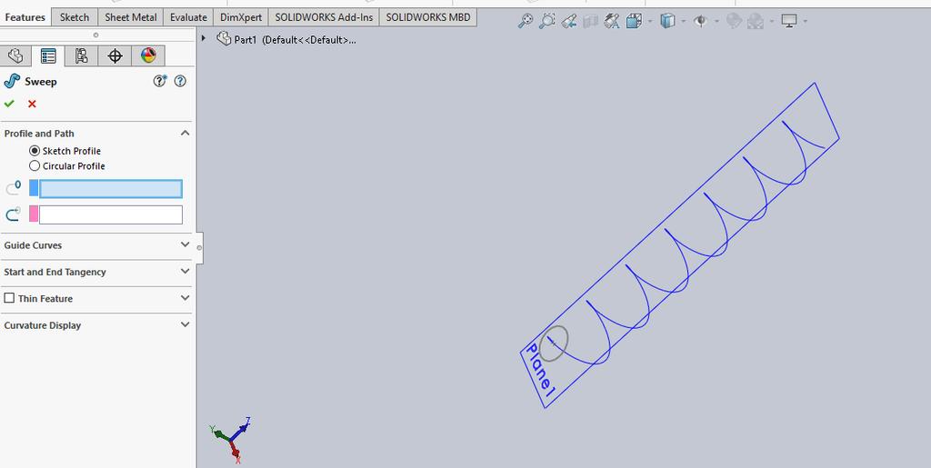
From the above fig. After sketching the path and profile select the sweep command First select the profile from property manager tree And then select
|
|
|
- Patricia Gibson
- 5 years ago
- Views:
Transcription
1 Chapter 5 In sweep command there is a) Two sketch profiles b) Two path c) One sketch profile and one path The sweep profile is used to create threads springs circular things and difficult geometry. For sweep profile The sketch must be non intersecting that mean the two sketches(profile and path) are at different planes Its profile must be close
2

3 From the above fig. After sketching the path and profile select the sweep command First select the profile from property manager tree And then select the path then ok The guide curve can also be used
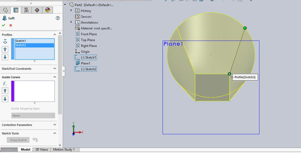
4 Loft: The loft command is used between two sketches.(true,false) The loft feature is an important tool for surface modeling. The loft feature creates a shape by making transitions between multiple profiles and guide curves. The sketch profile can be either closed or open The guide curves are used to create complex shapes
5 Draw first sketch Draw 2 nd sketch Select the lofted boss/base command Then in profile option select first sketch then 2 nd and use guide curves if need as shown in following fig. Then ok
6

7 Draft In how many ways the draft command is used in SolidWorks? Draft command used to remove material from part It used in different ways in SolidWorks

8 The natural draft will be like this This is at 30 degree
9 Parting line draft First select the upper face Then select the two edges which are parallel as shown then give angle Then ok As shown in the following fig.
10

11 And this is parting line draft result

12 This is step draft
13 Opening a part document: i)how the dimensions are fully defined in a sketch? ii)how to make a sketch after exit the sketch? Open a part from a folder Edit the sketch and change it if you want and give all dimensions so that it becomes fully defined as shown in the following

14 Fully defined sketch
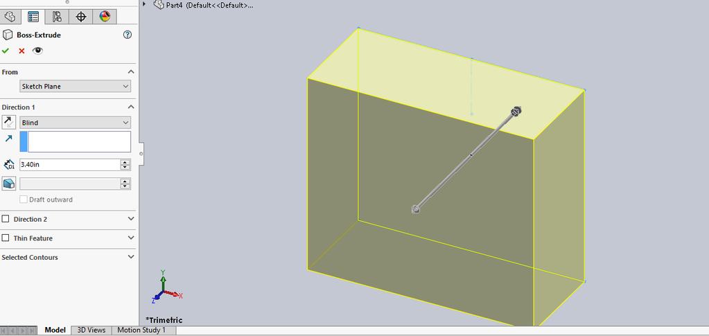
15 Exit the sketch The feature manager tree will appear Click on extruded boss/base The property manager will be like this There are other options like draft and direction 2 which may be used
16

17 Sketching the upper inlet port: Select the plane and click on the sketch to make new drawing on it Select the front plane in this case and sketch on it as shown

18 Sketch on it as shown
19 Revolve command the use of revolve command is easy and from this command we can draw complex geometry In revolve command first select the axis of rotation Then give the angle Then ok as shown in fig.

20 Revolve command
21 Fillet: a) Why fillet are used? b) What is difference between fillet and chamfer? Select the edges you want to fillet Then give radius value The edges selected can be edited by right click on the item to fillet And the delete and add other corner or edges The fillet command is shown in following fig/
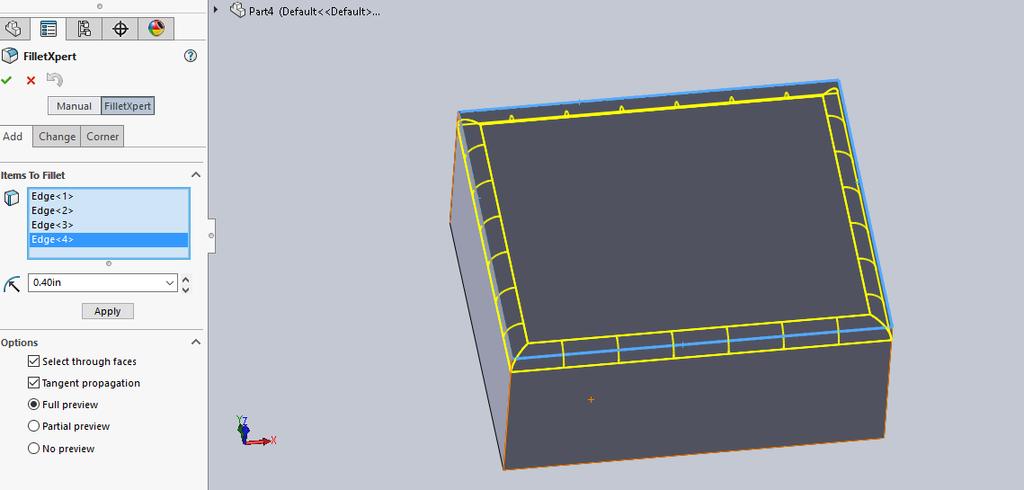
22 Fillet
 How many references are used to fully defined a new plane?")
23 Creating offset distance plane: a) Why offset plane is used? b) How many references are used to fully defined a new plane? The new plane need 3 references
24 From feature manager tree select the front plane to offset from Then enter any offset distance e.g. 5 inches Here we can set its direction either left or right from the front plane We can make number of plane

25 Offset plane

26 4 planes are created at equal distance as shown below:

27 Sketch the 1 st loft profile This is 1 st lofted profile And its fully defined As all line are black Select plane 1 And open a new sketch Select a rectangle and Draw sketch Add the dimensions And relations to fully defined

28 The 2 nd loft is sketch on the 2 nd plane as shown Select plane 2 And open a new sketch Select a rectangle and Draw sketch Add the dimensions And relations to fully defined

29 3 rd sketch for loft on 3 rd plane Select plane 2 And open a new sketch Select a circle and Draw sketch Add the dimensions And relations to fully defined

30 Create 4 th loft Select plane 4 And open a new sketch Select a circle and Draw sketch Add the dimensions And relations to fully defined
31 Creating a loft feature: Loft create when planes are out of phase angle(true,false) Exit the sketch and click on the lofted boss/base command Select all 4 sketches as shown in fig.in next slide Click ok
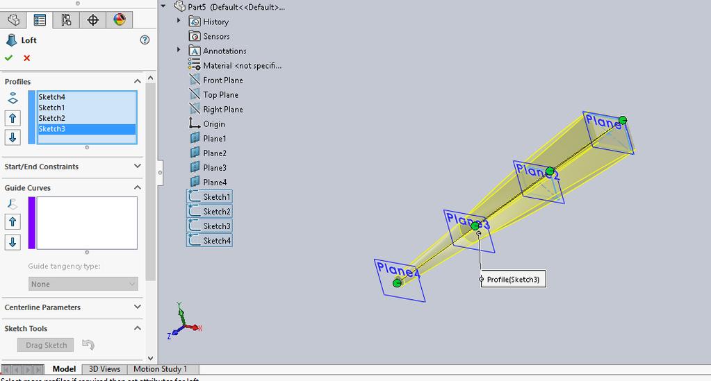
32
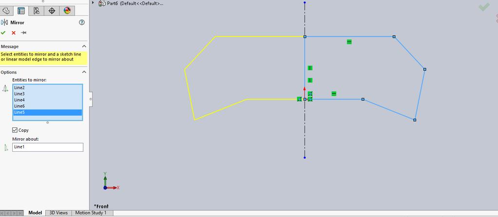
 Mirror in sketch manager is same as in feature manager(true,false) This is sketch I want to mirror about Centre line Select command")
33 Mirror command a) What is the difference between mirror and copy? b) Mirror in sketch manager is same as in feature manager(true,false) This is sketch I want to mirror about Centre line Select command mirror in sketch manager Select the entities to mirror then Selected the lines
34
35 Then mirror about and select center line Ok

36 shell: What is the purpose of shell command in solidworks? Make the part as shown Click on command shell Then give thickness to the part Then faces which are to be removed

37 Multi-thickness setting we can set thickness of different faces

38 The final shape after shell command is shown beloow
39 Rib: a) If the direction of arrow is outside the rib then it will not make rib(true, false) b) What are the application of rib? Make a sketch and extrude it and then select rib command Select a plane where you want to make a rib Sketch at this plane and give thickness to this rib and then ok As shown in following fig.
40
41 You can save the work as ctrl + s
10/14/2010. Chevy Malibu. Vehicle Design with Solidworks. Start SolidWorks Create a New SolidWorks Document. Miles, Rowardo B
 Chevy Malibu Vehicle Design with Solidworks Start SolidWorks Create a New SolidWorks Document Miles, Rowardo B 1 Click: Part and then OK Now you are ready to make a Part. 2 Right Toolbar: Document Properties:
DEPARTMENT OF MECHANICAL AND INDUSTRIAL ENGINEERING NORTHEASTERN UNIVERSITY
 DEPARTMENT OF MECHANICAL AND INDUSTRIAL ENGINEERING NORTHEASTERN UNIVERSITY CAPSULE PROGRAM Funded by NSF grant #0833636 Tutorial 02 3D Part Modeling SolidWorks 2010 Copyright 2010 Prof. Zeid 3D Part Modeling
SolidWorks Navigation
 SolidWorks Basics SolidWorks Navigation Command Bar Feature Tree Model Window Simple Box Select the Front plane Create a new sketch Create a Center Rectangle from the origin Smart Dimension the length
Hydro Hull. Chapter 21. Boat. A. Save as "HYDRO". Step 1. Open your HULL MID PLANE file (Chapter 2).
.") Chapter 21 Boat Hydro Hull A. Save as "HYDRO". Step 1. Open your HULL MID PLANE file (Chapter 2). Step 2. Click File Menu > Save As. Step 3. Key-in HYDRO for the filename and press ENTER. B. Delete Loft1,
Chapter 21 Boat Hydro Hull A. Save as "HYDRO". Step 1. Open your HULL MID PLANE file (Chapter 2). Step 2. Click File Menu > Save As. Step 3. Key-in HYDRO for the filename and press ENTER. B. Delete Loft1,
Feature-Based Modeling and Optional Advanced Modeling. ENGR 1182 SolidWorks 05
 Feature-Based Modeling and Optional Advanced Modeling ENGR 1182 SolidWorks 05 Today s Objectives Feature-Based Modeling (comprised of 2 sections as shown below) 1. Breaking it down into features Creating
Cube in a cube Fusion 360 tutorial
 Cube in a cube Fusion 360 tutorial n Before using these instructions, it is helpful to watch this video screencast of the CAD drawing actually being done in the software. Click to link to the video tutorial.
Introduction to Circular Pattern Flower Pot
 Prerequisite Knowledge Previous knowledge of the sketching commands Line, Circle, Add Relations, Smart Dimension is required to complete this lesson. Previous examples of Revolved Boss/Base, Cut Extrude,
COMPUTER AIDED ENGINEERING DESIGN (BFF2612) PART DESIGN Sketch Based Features
 PART DESIGN Sketch Based Features") COMPUTER AIDED ENGINEERING DESIGN (BFF2612) PART DESIGN Sketch Based Features by Dr. Mohd Nizar Mhd Razali Faculty of Manufacturing Engineering mnizar@ump.edu.my MODELLING STRATEGIES Determine model type
COMPUTER AIDED ENGINEERING DESIGN (BFF2612) PART DESIGN Sketch Based Features by Dr. Mohd Nizar Mhd Razali Faculty of Manufacturing Engineering mnizar@ump.edu.my MODELLING STRATEGIES Determine model type
Model House Exercise-( Extrude)
") -( Extrude) Prerequisite knowledge Focus of the lesson Commands Used This lesson requires an understanding of using the sketch commands including Inserting a new sketch Adding sketch geometry Understanding
-( Extrude) Prerequisite knowledge Focus of the lesson Commands Used This lesson requires an understanding of using the sketch commands including Inserting a new sketch Adding sketch geometry Understanding
Shaft Hanger - SolidWorks
 ME-430 INTRODUCTION TO COMPUTER AIDED DESIGN Shaft Hanger - SolidWorks BY: DR. HERLI SURJANHATA ASSIGNMENT Submit TWO isometric views of the Shaft Hanger with your report, 1. Shaded view of the trimetric
SolidWorks Part I - Basic Tools SDC. Includes. Parts, Assemblies and Drawings. Paul Tran CSWE, CSWI
 SolidWorks 2015 Part I - Basic Tools Includes CSWA Preparation Material Parts, Assemblies and Drawings Paul Tran CSWE, CSWI SDC PUBLICATIONS Better Textbooks. Lower Prices. www.sdcpublications.com Powered
Digital Camera Exercise
 Commands Used New Part This lesson includes Sketching, Extruded Boss/Base, Extruded Cut, Fillet, Chamfer and Text. Click File, New on the standard toolbar. Select Part from the New SolidWorks Document
1. Open the Feature Modeling demo part file on the EEIC website. Ask student about which constraints needed to Fully Define.
 BLUE boxed notes are intended as aids to the lecturer RED boxed notes are comments that the lecturer could make Control + Click HERE to view enlarged IMAGE and Construction Strategy he following set of
How to Build a Game Console. David Hunt, PE
 How to Build a Game Console David Hunt, PE davidhunt@outdrs.net Covering: Drafts Fillets Shells Patterns o Linear o Circular Using made-for-the-purpose sketches to define reference geometry Using reference
Spatula. Spatula SW 2015 Design & Communication Graphics Page 1
 Spatula Introduction: The model shown in the picture is made of three parts, - the base, the washer and the handle. The base requires the use of Spline and Style Spline command, Slot command and Mirror
Introducing SolidWorks
 Introducing SolidWorks SAAST Robotics 2008 SolidWorks Software Visually-based 3-D Mechanical design software Engineers and Designers use it to: Quickly sketch out ideas Experiment with features, dimensions
SolidWize. Online SolidWorks Training. Simple Sweep: Head Scratcher
 SolidWize Online SolidWorks Training Simple Sweep: Head Scratcher Step 1: Creating the Handle: Sketch Using Inches as the unit create a sketch on the Front plane. Start with the sketch shown below: Create
SolidWorks 95 User s Guide
 SolidWorks 95 User s Guide Disclaimer: The following User Guide was extracted from SolidWorks 95 Help files and was not originally distributed in this format. All content 1995, SolidWorks Corporation Contents
Inventor Activity 5: Lofted Vase
 Inventor Activity 5: Lofted Vase In this tutorial, you will use a few new commands to create a free form Lofted object. Sometimes you want to create an object that is not made up of square, flat, or perfectly
Solidworks Tutorial Pencil
 The following instructions will be used to help you create a Pencil using Solidworks. These instructions are ordered to make the process as simple as possible. Deviating from the order, or not following
AEROPLANE. Create a New Folder in your chosen location called Aeroplane. The four parts that make up the project will be saved here.
 AEROPLANE Prerequisite Knowledge Previous knowledge of the following commands is required to complete this lesson. Sketching (Line, Rectangle, Arc, Add Relations, Dimensioning), Extrude, Assemblies and
Veerapandian.K Mechanical Engg Vedharanyam A manual to mechanical designers How Solid works Works?
 Compiled by Veerapandian.K Mechanical Engg Vedharanyam-614 810 A manual to mechanical designers How Solid works Works? Solid works Overview Solid works main idea is user to create drawing directly in 3D
Basic Features. In this lesson you will learn how to create basic CATIA features. Lesson Contents: CATIA V5 Fundamentals- Lesson 3: Basic Features
 Basic Features In this lesson you will learn how to create basic CATIA features. Lesson Contents: Case Study: Basic Features Design Intent Stages in the Process Determine a Suitable Base Feature Create
g. Click once on the left vertical line of the rectangle.
 This drawing will require you to a model of a truck as a Solidworks Part. Please be sure to read the directions carefully before constructing the truck in Solidworks. Before submitting you will be required
Bottom Rail. Chapter 2. Chair. A. Weldments Toolbar. Step 1. Click File Menu > New, click Part and OK. B. 3D Sketch.
 Chapter 2 Chair Bottom Rail A. Weldments Toolbar. Step 1. Click File Menu > New, click Part and OK. Step 2. Right click Sketch on the Command Manager toolbar and select Weldments, Fig. 1. Step 3. Click
Objectives. Inventor Part Modeling MA 23-1 Presented by Tom Short, P.E. Munro & Associates, Inc
 Objectives Inventor Part Modeling MA 23-1 Presented by Tom Short, P.E. Munro & Associates, Inc To demonstrate most of the sketch tools and part features in : Inventor Release 6 And, to show logical techniques
Lab 3 Introduction to SolidWorks I Silas Bernardoni 10/9/2008
 1 Introduction This lab is designed to provide you with basic skills when using the 3D modeling program SolidWorks. You will learn how to build parts, assemblies and drawings. You will be given a physical
SolidWorks Reference Geometry
 SolidWorks Reference Geometry IDeATe Laser Micro Part 2 Dave Touretzky and Susan Finger 1. Symmetry and Reference Geometry Today, you ll make this part bear-like face and then cut it on the laser cutter:
Introduction to Revolve - A Glass
 Introduction to Revolve - A Glass Design & Communication Graphics 1 Object Analysis sheet Design & Communication Graphics 2 Prerequisite Knowledge Previous knowledge of the following commands are required
Beginner s Guide to SolidWorks Level I
 Beginner s Guide to SolidWorks 2013 - Level I Parts, Assemblies, Drawings, Simulation Xpress Alejandro Reyes MSME, CSWP, CSWI SDC PUBLICATIONS Schroff Development Corporation Better Textbooks. Lower Prices.
LABORATORY MANUAL COMPUTER AIDED DESIGN LAB
 LABORATORY MANUAL COMPUTER AIDED DESIGN LAB Sr. No 1 2 3 Experiment Title Setting up of drawing environment by setting drawing limits, drawing units, naming the drawing, naming layers, setting line types
Explanation of buttons used for sketching in Unigraphics
 Explanation of buttons used for sketching in Unigraphics Sketcher Tool Bar Finish Sketch is for exiting the Sketcher Task Environment. Sketch Name is the name of the current active sketch. You can also
Introduction to Autodesk Inventor User Interface Student Manual MODEL WINDOW
 Emmett Wemp EDTECH 503 Introduction to Autodesk Inventor User Interface Fill in the blanks of the different tools available in the user interface of Autodesk Inventor as your instructor discusses them.
Sash Clamp. Sash Clamp SW 2015 Design & Communication Graphics Page 1.
 Sash Clamp 1 Introduction: The Sash clamp consists of nine parts. In creating the clamp we will be looking at the improvements made by SolidWorks in linear patterns, adding threads and in assembling the
Chair. Bottom Rail. on the Command Manager. on the Weldments toolbar.
 Chapter 2 Chair Bottom Rail A. Weldments Toolbar. Step 1. Click File Menu > New, click Part and OK. Step 2. Right click Sketch on the Command Manager toolbar and select Weldments, Fig. 1. Step 3. Click
Engineering & Computer Graphics Workbook Using SolidWorks 2014
 Engineering & Computer Graphics Workbook Using SolidWorks 2014 Ronald E. Barr Thomas J. Krueger Davor Juricic SDC PUBLICATIONS Better Textbooks. Lower Prices. www.sdcpublications.com Powered by TCPDF (www.tcpdf.org)
LAB 1A: Intro to SolidWorks: 2D -> 3D Brackets
 LAB 1A: Intro to SolidWorks: 2D -> 3D Brackets Set units Create Sketch Add relations Linear patterns Mirror Fillet Extrude Extrude cut First, set units. click Option on top of main menu Open Document Properties
SOLIDWORKS 2016 Advanced Techniques
 SOLIDWORKS 2016 Advanced Techniques Mastering Parts, Surfaces, Sheet Metal, SimulationXpress, Top Down Assemblies, Core & Cavity Molds Paul Tran CSWE, CSWI SDC PUBLICATIONS Better Textbooks. Lower Prices.
Engineering & Computer Graphics Workbook Using SOLIDWORKS
 Engineering & Computer Graphics Workbook Using SOLIDWORKS 2017 Ronald E. Barr Thomas J. Krueger Davor Juricic SDC PUBLICATIONS Better Textbooks. Lower Prices. www.sdcpublications.com Powered by TCPDF (www.tcpdf.org)
Beginner s Guide to SolidWorks Level I
 Beginner s Guide to SolidWorks 2014 - Level I Parts, Assemblies, Drawings, PhotoView 360 and Simulation Xpress Videos Now includes SolidWorks training videos Alejandro Reyes MSME, CSWP, CSWI Multimedia
CATIA Instructor-led Live Online Training Program
 Course Outline Introduction & Understanding to CATIA Environment Introduction & Understanding to CATIA interface Starting new file Understand the Sketcher workbench of CATIA V5 Start a new file in the
Solidworks tutorial. 3d sketch project. A u t h o r : M. G h a s e m i. C o n t a c t u s : i n f s o l i d w o r k s a d v i s o r.
 Solidworks tutorial 3d sketch project A u t h o r : M. G h a s e m i C o n t a c t u s : i n f o @ s o l i d w o r k s a d v i s o r. c o m we will create this frame during the tutorial : In this tutorial
Starting a 3D Modeling Part File
 1 How to Create a 3D Model and Corresponding 2D Drawing with Dimensions, GDT (Geometric Dimensioning and Tolerance) Symbols and Title Block in SolidWorks 2013-2014 By Edward Locke This tutorial will introduce
Advanced Modeling Techniques Sweep and Helical Sweep
 Advanced Modeling Techniques Sweep and Helical Sweep Sweep A sweep is a profile that follows a path placed on a datum. It is important when creating a sweep that the designer plans the size of the path
Education Curriculum Combined Specialist
 Education Curriculum Combined Specialist Invest your time in imagining next generation designs. Here s what we will teach you to give shape to your imagination. CATIA Combined Specialist Course CATIA Mechanical
Product Modelling in Solid Works
 Product Modelling in Solid Works In the following exercise you will use solid works to construct the computer mouse shown opposite. In this exercise you will use a number of advanced features to achieve
Beginner s Guide to SolidWorks Alejandro Reyes, MSME Certified SolidWorks Professional and Instructor SDC PUBLICATIONS
 Beginner s Guide to SolidWorks 2008 Alejandro Reyes, MSME Certified SolidWorks Professional and Instructor SDC PUBLICATIONS Schroff Development Corporation www.schroff.com www.schroff-europe.com Part Modeling
Creo Revolve Tutorial
 Creo Revolve Tutorial Setup 1. Open Creo Parametric Note: Refer back to the Creo Extrude Tutorial for references and screen shots of the Creo layout 2. Set Working Directory a. From the Model Tree navigate
for Solidworks TRAINING GUIDE LESSON-9-CAD
 for Solidworks TRAINING GUIDE LESSON-9-CAD Mastercam for SolidWorks Training Guide Objectives You will create the geometry for SolidWorks-Lesson-9 using SolidWorks 3D CAD software. You will be working
SolidWorks Design & Technology
 SolidWorks Design & Technology Training Course at PHSG Ex 5. Lego man Working with part files 8mm At first glance the Lego man looks complicated but I hope you will see that if you approach a project one
Lesson 10: Loft Features
 10 Goals of This Lesson Your students will be able to create the following part: profiles chisel This lesson plan corresponds to the Loft Features chapter of SolidWorks Getting Started. SolidWorks Student
SOLIDWORKS Essentials
 SOLIDWORKS Essentials Length: 5 days Prerequisite: Mechanical design experience and experience with the Windows operating system. Description: SOLIDWORKS Essentials teaches you how to use SOLIDWORKS mechanical
1. Creating geometry based on sketches 2. Using sketch lines as reference 3. Using sketches to drive changes in geometry
 4.1: Modeling 3D Modeling is a key process of getting your ideas from a concept to a read- for- manufacture state, making it core foundation of the product development process. In Fusion 360, there are
Introduction to 3D CAD with SolidWorks. Jianan Li
 Introduction to 3D CAD with SolidWorks Jianan Li Create a New Part The first time you launch SolidWorks, it asks you to set the default units and dimension standard. Make sure you have IPS and ANSI selected,
Student + Instructor:
 BLUE boxed notes are intended as aids to the lecturer RED boxed notes are comments that the lecturer could make Show 01 Solid Modeling Intro slides quickly. SolidWorks Layout slides are on EEIC for reference
SDC. SolidWorks Tutorial 2001Plus. A Competency Project Based Approach Utilizing 3D Solid Modeling. David C. Planchard & Marie P.
 2001Plus A Competency Project Based Approach Utilizing 3D Solid Modeling David C. Planchard & Marie P. Planchard SDC PUBLICATIONS www.schroff.com www.schroff-europe.com Project 2 Below are the desired
Part Design Fundamentals
 Part Design Fundamentals 1 Course Presentation Objectives of the course In this course you will learn basic methods to create and modify solids features and parts Targeted audience New CATIA V5 Users 1
EXERCISE ONE: BEACH BUGGY.
 EXERCISE ONE: BEACH BUGGY. Prerequisite knowledge Students should have completed Exercises from the file: Introduction to Assemblies Concept Mates Focus of lesson Commands Used This lesson will focus on
SolidWize. Online SolidWorks Training. Lofts: Tea Pot
 SolidWize Online SolidWorks Training Lofts: Tea Pot Step 1: Creating the Body Using inches as the unit, create the following sketch on the top plane. We will now add a plane above the top plane so that
Engineering Technology
 Engineering Technology Introduction to Parametric Modelling Engineering Technology 1 See Saw Exercise Part 1 Base Commands used New Part This lesson includes Sketching, Extruded Boss/Base, Hole Wizard,
Below are the desired outcomes and usage competencies based on the completion of Project 4.
 Engineering Design with SolidWorks Project 4 Below are the desired outcomes and usage competencies based on the completion of Project 4. Project Desired Outcomes: An understanding of the customer s requirements
Introduction to Sheet Metal Features SolidWorks 2009
 SolidWorks 2009 Table of Contents Introduction to Sheet Metal Features Base Flange Method Magazine File.. 3 Envelopment & Development of Surfaces.. 14 Development of Transition Pieces.. 23 Conversion to
Siemens NX11 tutorials. The angled part
 Siemens NX11 tutorials The angled part Adaptation to NX 11 from notes from a seminar Drive-to-trial organized by IBM and GDTech. This tutorial will help you design the mechanical presented in the figure
Alibre Design Tutorial: Loft, Extrude, & Revolve Cut Loft-Tube-1
 Alibre Design Tutorial: Loft, Extrude, & Revolve Cut Loft-Tube-1 Part Tutorial Exercise 5: Loft-Tube-1 [Complete] In this Exercise, We will set System Parameters first, then part options. Then, in sketch
Using Siemens NX 11 Software. The connecting rod
 Using Siemens NX 11 Software The connecting rod Based on a Catia tutorial written by Loïc Stefanski. At the end of this manual, you should obtain the following part: 1 Introduction. Start NX 11 and open
Wireless Mouse Surfaces
 Wireless Mouse Surfaces Design & Communication Graphics Table of Contents Table of Contents... 1 Introduction 2 Mouse Body. 3 Edge Cut.12 Centre Cut....14 Wheel Opening.. 15 Wheel Location.. 16 Laser..
1. Create a 2D sketch 2. Create geometry in a sketch 3. Use constraints to position geometry 4. Use dimensions to set the size of geometry
 2.1: Sketching Many features that you create in Fusion 360 start with a 2D sketch. In order to create intelligent and predictable designs, a good understanding of how to create sketches and how to apply
Module 2.1, 2.2 Review. EF101 Analysis & Skills Module 2.3. Sketched Features and Operations. On-line Help Two Locations
 EF101 Analysis & Skills Module 2.3 Engineering Graphics Revolved Features Placed Features Work Features Module 2.1, 2.2 Review What are the three types of operations for adding features to the base feature?
Module 1G: Creating a Circle-Based Cylindrical Sheet-metal Lateral Piece with an Overlaying Lateral Edge Seam And Dove-Tail Seams on the Top Edge
 Inventor (10) Module 1G: 1G- 1 Module 1G: Creating a Circle-Based Cylindrical Sheet-metal Lateral Piece with an Overlaying Lateral Edge Seam And Dove-Tail Seams on the Top Edge In Module 1A, we have explored
Lesson 4 Holes and Rounds
 Lesson 4 Holes and Rounds 111 Figure 4.1 Breaker OBJECTIVES Sketch arcs in sections Create a straight hole through a part Complete a Sketched hole Understand the Hole Tool Use Info to extract information
Table of Contents. Dedication Preface. Chapter 1: Introduction to CATIA V5-6R2015. Chapter 2: Drawing Sketches in the Sketcher Workbench-I.
 Table of Contents Dedication Preface iii xvii Chapter 1: Introduction to CATIA V5-6R2015 Introduction to CATIA V5-6R2015 1-2 CATIA V5 Workbenches 1-2 System Requirements 1-4 Getting Started with CATIA
Toothbrush Holder. A drawing of the sheet metal part will also be created.
 Prerequisite Knowledge Previous knowledge of the following commands is required to complete this lesson; Sketch (Line, Centerline, Circle, Add Relations, Smart Dimension,), Extrude Boss/Base, and Edit
Alternatively, the solid section can be made with open line sketch and adding thickness by Thicken Sketch.
 Sketcher All feature creation begins with two-dimensional drawing in the sketcher and then adding the third dimension in some way. The sketcher has many menus to help create various types of sketches.
ME Week 2 Project 2 Flange Manifold Part
 1 Project 2 - Flange Manifold Part 1.1 Instructions This project focuses on additional sketching methods and sketching commands. Revolve and Work features are also introduced. The part being modeled is
Copyrighted. Material. Copyrighted. Material. Copyrighted. Material. Copyrighted. Material
 ENGINEERING & COMPUTER GRAPHICS WORKBOOK Using SolidWorks 2008 Ronald E. Barr Thomas J. Krueger Theodore A. Aanstoos Davor Juricic SDC PUBLICATIONS Schroff Development Corporation www.schroff.com Better
Solidworks: Lesson 4 Assembly Basics and Toolbox. UCF Engineering
 Solidworks: Lesson 4 Assembly Basics and Toolbox UCF Engineering Solidworks We have now completed the basic features of part modeling and it is now time to begin constructing more complex models in the
Engineering Design with SolidWorks A Step-by-Step Project Based Approach Utilizing 3D Solid Modeling. David C. Planchard & Marie P.
 Engineering Design with SolidWorks 2003 A Step-by-Step Project Based Approach Utilizing 3D Solid Modeling David C. Planchard & Marie P. Planchard SDC PUBLICATIONS www.schroff.com www.schroff-europe.com
TRAINING COURSE PROSPECTUS
 SOLIDWORKS Essentials Duration: Prerequisites: Description: The topics covered in this course are: 4 Days Mechanical design experience; experience with the Windows operating system SOLIDWORKS Essentials
Creo Parametric 4.0 Basic Design
 Creo Parametric 4.0 Basic Design Contents Table of Contents Introduction...1 Objective of This Textbook...1 Textbook Outline...2 Textbook Conventions...3 Exercise Files...3 System Configuration...4 Notes
Create A Mug. Skills Learned. Settings Sketching 3-D Features. Revolve Offset Plane Sweep Fillet Decal* Offset Arc
 Create A Mug Skills Learned Settings Sketching 3-D Features Slice Line Tool Offset Arc Revolve Offset Plane Sweep Fillet Decal* Tutorial: Creating A Custom Mug There are somethings in this world that have
Assembly Receiver/Hitch/Ball/Pin to use for CAD LAB 5A and 5B:
 MECH 130 CAD LAB 5 SPRING 2017 due Friday, April 21, 2016 at 4:30 PM All of LAB 5 s hardcopies will be working drawing layouts. Do not print out from the part file. We will be using the ME130DRAW drawing
Lesson 6 2D Sketch Panel Tools
 Lesson 6 2D Sketch Panel Tools Inventor s Sketch Tool Bar contains tools for creating the basic geometry to create features and parts. On the surface, the Geometry tools look fairly standard: line, circle,
Introduction to 3D Printing. Activity 1: Design a keychain using computer-aided design software
 Introduction to 3D Printing Activity 1: Design a keychain using computer-aided design software 1 In this activity we ll design a keychain name tag and learn the fundamentals of computer-aided design, the
Autodesk Inventor 2016 Creating Sketches
 Autodesk Inventor 2016 Creating Sketches 2D Sketch Practice 1 1. Launch Autodesk Inventor 2016 2. Create a new Part file (.ipt) 3. Save File As a. Click on the save icon. b. Save you file onto your flash
SOLIDWORKS 2015 and Engineering Graphics
 SOLIDWORKS 2015 and Engineering Graphics An Integrated Approach Randy H. Shih SDC PUBLICATIONS Better Textbooks. Lower Prices. www.sdcpublications.com Powered by TCPDF (www.tcpdf.org) Visit the following
WEEK 5: Shaft Modeling (C51X01, C51X02) Revolved Features, Chamfer
 Revolved Features, Chamfer") WEEK 5: Shaft Modeling (C51X01, C51X02) Revolved Features, Chamfer 1. Creating the Shaft Model 1. File> New> Part, Name: C51X01> OK 2. Insert> Revolve> Placement> Define> select TOP datum plane> Sketch
WEEK 5: Shaft Modeling (C51X01, C51X02) Revolved Features, Chamfer 1. Creating the Shaft Model 1. File> New> Part, Name: C51X01> OK 2. Insert> Revolve> Placement> Define> select TOP datum plane> Sketch
Diane Burton, STEM Outreach.
 123D Design Tutorial: LED decoration Before using these instructions, it is very helpful to watch this video screencast of the CAD drawing actually being done in the software. Click this link for the video
Copyrighted. Material. Copyrighted. Material. Copyrighted. Material. Copyrighted. Material
 ENGINEERING & COMPUTER GRAPHICS WORKBOOK Using SolidWorks 2005 Ronald E. Barr Thomas J. Krueger Theodore A. Aanstoos Davor Juricic SDC PUBLICATIONS Schroff Development Corporation www.schroff.com www.schroff-europe.com
Revit Structure 2012 Basics:
 SUPPLEMENTAL FILES ON CD Revit Structure 2012 Basics: Framing and Documentation Elise Moss autodesk authorized publisher SDC PUBLICATIONS www.sdcpublications.com Schroff Development Corporation Structural
Essentials of SOLIDWORKS 2015 (4+ Days) * Ve-I Bonus! * File Management + SimulationXpress
 * Ve-I Bonus! * File Management + SimulationXpress") Essentials of SOLIDWORKS 2015 (4+ Days) * Ve-I Bonus! * File Management + SimulationXpress Overview What is SOLIDWORKS? Interface Tour View Manipulation Provides some background info on the SOLIDWORKS
Essentials of SOLIDWORKS 2015 (4+ Days) * Ve-I Bonus! * File Management + SimulationXpress Overview What is SOLIDWORKS? Interface Tour View Manipulation Provides some background info on the SOLIDWORKS
Activity 1 Modeling a Plastic Part
 Activity 1 Modeling a Plastic Part In this activity, you will model a plastic part. When completed, your plastic part should look like the following two illustrations. While building this model, take time
Copyright by J.W. Zuyderduyn Page 1
 Copyright by J.W. Zuyderduyn www.learnsolidworks.com Page 1 A step by step SolidWorks Tutorial Copyright by J.W. Zuyderduyn www.learnsolidworks.com Page 2 About the Author Hi, my name is Jan-Willem Zuyderduyn
SolidWorks. SolidWorks Workbook Advanced Modeling. Version 2009
 SolidWorks SolidWorks Workbook Advanced Modeling Version 2009 SolidWorks Europe 53, Avenue de l Europe Immeuble DSP 13090 AIX-EN-PROVENCE, France Tel: +33 (0)4 13 10 80 20 Fax: +33 (0)4 13 10 80 21 Email:
Canoe Mirroring Lofts
 Canoe Mirroring Lofts 1. Set Units to Inches 2. Create a New Design. 3. Save the Design as canoeinl811 in your Canoe folder. 4. Create a New Sketch on the Frontal Workplane. Name the Sketch Middle. 5.
Pro/DESKTOP Tutorial Drafting Bow Compass
 Pro/DESKTOP Tutorial Drafting Bow Compass Michael Flowers 2005 1 Objectives: To develop confidence with the Pro/DESKTOP software. To learn to utilize extrude, project, revolve, round, and chamfer features.
Introduction to Creo Parametric 2.0
 Introduction to Creo Parametric 2.0 Overview Course Code Course Length TRN-3902-T 5 Days In this course, you will learn core modeling skills and quickly become proficient with Creo Parametric 2.0. Topics
EN1740 Computer Aided Visualization and Design Spring /1/2012 Brian C. P. Burke
 EN1740 Computer Aided Visualization and Design Spring 2012 3/1/2012 Brian C. P. Burke Last time: Measure Shell Surfaces Best practices/appropriate Uses Parametric From standard features Tonight: Finish
Spokane Public Schools Course: Drafting and Design Technology
 Spokane Public Schools Drafting and Design Technology Course: Drafting and Design Technology Total Framework Hours up to: 180 hours CIP Code: 140102 Exploratory Preparatory Date Last Modified: 4/2/2015