Introduction to Circular Pattern Flower Pot
|
|
|
- Shon Nelson
- 5 years ago
- Views:
Transcription

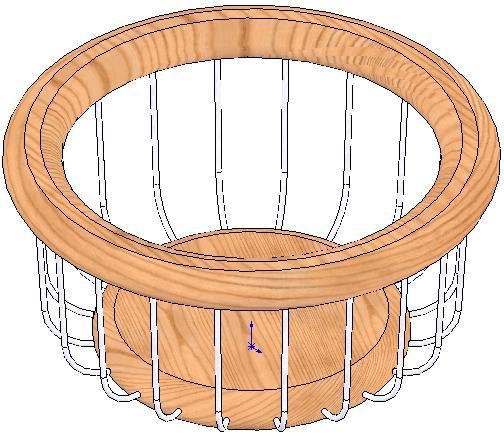
1 Prerequisite Knowledge Previous knowledge of the sketching commands Line, Circle, Add Relations, Smart Dimension is required to complete this lesson. Previous examples of Revolved Boss/Base, Cut Extrude, Chamfer, Fillet, Shell and Editing Appearance should also have been completed. Focus of the Lesson On completion of this lesson you will have used: The Line, Centerline, Circle, 3 Point Circle, Add Relation, Convert Entities and Smart Dimension commands form the Sketch Toolbar. The Revolved Boss/Base, Cut Extrude, Chamfer, Fillet, Shell and Circular Pattern commands from the Features Toolbar. Circular Pattern is used when circularly spacing multiple instances of one or more features around an axis. The pattern will be created on the same face of the model as the initial feature to be patterned. This is called the Seed Feature. The Property Manager of the Circular Pattern controls the layout of the pattern. To create the pattern an axis must be chosen to revolve around. Other parameters to be set include the degrees of revolution, the number of instances and whether these will be equally spaced. The pattern can be modified to allow certain instances of the patterned feature to be skipped. RD5 DCG/Ex1 Design & Communication Graphics - 1 -

2 Commands Used This lesson includes Sketching (Line, Circle, Centerline, Add Relations, Convert Entities and Smart Dimension), Revolved Boss/Base, Cut Extrude, Chamfer, Fillet, Shell, Circular Pattern and Edit Materials. Where to start? It is important to analyse the design of a flower pot prior to starting the model. The model is created by revolving a sketch so that the axis for this feature will provide the axis for the circular patterns on the base. Sketch to generate feature Revolved feature Getting started Open a new part and save as Flower pot. Choosing a plane Select Sketch on the sketch toolbar. Choose the Front plane. The view will automatically change to a front view. Creating a sketch Select the Line command, and starting from the origin create a sketch similar to the one shown above. It is good practice when creating a sketch to follow the sequence sketch, add relations and dimension. RD5 DCG/Ex1 Design & Communication Graphics - 2 -


3 Select the Add Relation command from the sketch toolbar. Select the two lines indicated and choose Parallel in the add relation property manager. Note: The little blue symbols at the sketching stage. indicate the relationship a line may have gained Dimensioning the Select Smart Dimension from the sketch toolbar and dimension the Sketch sketch as shown below. To set the angle, select the two lines indicated, enter 85 in the Modify Box and confirm. RD5 DCG/Ex1 Design & Communication Graphics - 3 -


4 Note The sketch will change from blue to black when it is fully defined. To Confirm the sketch. Creating the feature Select Features from the Command Manager. The Features toolbar has now replaced the Sketch toolbar along the top of the screen. Select Revolved Boss/Base, the sketch rotates to a trimetric view. In the Revolved Boss/Base feature property manager select the 150mm vertical edge of the sketch as the axis for the revolution. At this point a preview of the feature will appear. Click OK button to create the feature. Alternatively select the confirmation corner. from the RD5 DCG/Ex1 Design & Communication Graphics - 4 -


5 Completed feature: This is the first completed feature of the part. The sketch has been absorbed into the Revolve 1 feature in the Feature Manager. Renaming a feature: Select in the Feature Manager Tree, press the F2 key and type the new name Main Body to replace Revolve1. Creating the indents on the base Creating the sketch Select the Sketch toolbar from the Command Manager. Enter the sketch mode by selecting at the start of the Sketch toolbar. When prompted select the bottom face and select Normal To from the View Command. The model will rotate to a view looking perpendicular to the bottom surface. Note: Select the Rotate View icon in the View Toolbar. Alternatively by pressing and holding down the wheel on the mouse the rotate view mode is activated. Also the arrows keys on the keyboard can be used. Select the Centerline Sketch command. Draw a vertical line on the chosen surface from the centre. Select the Line sketch command and draw the vertical line shown. Click to end the vertical line, remain in the Line command. By moving the pointer as if to start a second line and then doubling back to the start point and starting again, the software will automatically change into circle/arc mode. Draw a semi-circle. Click RD5 DCG/Ex1 Design & Communication Graphics - 5 -


6 to complete the semi-circle and the software changes back to the Line command. Draw a second line parallel to the first. Select the circular edge of the base. Select the Convert entities command to convert this circle to a circle within the sketch. Use the Trim Entities command to trim the circle to the required size. Select the Add Relation command. Select the centerline and the centre point of the semi-circle and in the Add Relation Property Manager make them coincident. Using Smart Dimension apply the above dimensions to the circle. Confirm the dimensions and exit the sketch. Creating the feature Select Features from the Command Manager. The Features toolbar has now replaced the Sketch toolbar along the top of the screen. Choose Extruded Cut. Select Isometric View form the Command View. The feature previews in isometric. RD5 DCG/Ex1 Design & Communication Graphics - 6 -


7 Use the Extrude Feature Manager on the left of the screen set up the feature. to Extrude Feature Settings End Condition = Blind Depth = 4mm Click OK button to create the feature. Rename the feature Base Cut. Adding a Chamfer A 4mm chamfer is now added to the top edge of the Base Cut. Rotate the model to view the base cut. Select Chamfer from the Features toolbar. In the Chamfer Feature Manager set the parameters as shown and select the top edge of the extruded cut in the graphics area. Note: The flip direction check box will angle the chamfer inwards. Confirm the feature. Adding a Fillet A fillet is now added to the top and bottom edges of the chamfer. Select Fillet Toolbar. in the Features In the Fillet Feature Tree Manager set the Fillet radius to 2mm and the select the top and bottom edges of the chamfered cut in the graphics area. Confirm the feature. RD5 DCG/Ex1 Design & Communication Graphics - 7 -


8 The completed feature should now look like this. Pattern the Feature The Base Cut can now be patterned on the bottom surface of the model. In the View menu activate the Temporary Axes. The axis from the original Revolved Boss/Base will become visible. Choose the Circular Pattern Command from the features toolbar. In the Circular Pattern Feature Manager select the visible axis, instances = 4 with equal spacing. Expand the Feature Tree of the Flower Pot (left click on the + sign) in the graphics area and select Base Cut, Chamfer1 and Fillet1 as the Seed Features to pattern. Alternatively click the Features to Pattern box and select them on the actual model. Click OK to create the pattern. Rename Feature Rename the feature Base Pattern RD5 DCG/Ex1 Design & Communication Graphics - 8 -


9 Shell Command It is also important to shell after the cut feature on the base has been patterned. If the shell was created first the 4mm deep indents could not have been created in a shelled feature 1mm thick. Select the Shell command on the Features toolbar. In the Shell Feature Manager Distance = 1mm Select the top surface of the model. Tick Show Preview Click OK button to create the pattern. Rename the Feature Select the Feature in the Feature Manager Tree, press F2 key and rename Base Cut Pattern. This is how the completed shell feature should look when complete. Creating the holes Creating the Sketch A circular hole is created first on the base and then patterned. Select the Sketch toolbar. Select Sketch on the Sketch toolbar. When prompted, select the bottom surface as the plane to sketch on. This will require the model to be rotated. Select Normal To from the View Command Menu. Select the Centerline Sketch command. Sketch two centerlines from the centre of the circle to the circumference of the base circle. Add Relations to make one RD5 DCG/Ex1 Design & Communication Graphics - 9 -


10 horizontal and Smart Dimension the angle to Select the Circle Command. Sketch a circle centred on the centerline and Smart Dimension as shown. Click OK to complete the sketch. Finish the sketch by clicking on the Exit Sketch icon or Exit Sketch in the Confirmation Corner. Creating the Feature Select the Features Toolbar in the Command Manager. Select Extrude Cut. Change the view to Isometric in the View Command. In the Cut Extrude Feature Manager set the direction to Through All. Click OK to complete the feature. Select this feature in the Feature Tree Manager, press the F2 key and rename the feature Circular Hole. Pattern the Feature The Circular Hole feature can now be patterned with similar settings as the previous Circular Pattern. Select the same axis as previously, instances = 8 with equal spacing. RD5 DCG/Ex1 Design & Communication Graphics


11 Click OK to complete the feature. Rename the Feature In the Feature Manager Tree rename the pattern Base Circles Pattern. The model should now look like this. Note: It is advisable to save the part at regular intervals. This can done using the Quicksave button. Adding an edge A protruding edge is added to top of the Flower Pot. Sketch the profile below on the Right plane. Zoom to the top corner. The graphics area will enlarge the selected area. Select the Line command and sketch as shown in the diagram opposite. Ensure the outer line is parallel to the side of the Flower Pot. Dimension as shown. Creating the Feature Select Features in the command Manager and select Revolved Boss/Base. Select the same axis as before. Click OK to confirm the feature. One last Fillet Add a 1mm fillet feature to the underside surface of the external rim. RD5 DCG/Ex1 Design & Communication Graphics


12 Adding color To add colour to the model, right click on the Flower Pot feature in the Feature Manager Tree. In the menu select Appearance and Color. In the Color and Optics Property Manager select a colour for the Flower Pot. Click OK to complete. Save the completed model. RD5 DCG/Ex1 Design & Communication Graphics


13 Further Exercises RD5 DCG/Ex1 Design & Communication Graphics

14 RD5 DCG/Ex1 Design & Communication Graphics

15 RD5 DCG/Ex1 Design & Communication Graphics
16 RD5 DCG/Ex1 Design & Communication Graphics
17 RD5 DCG/Ex1 Design & Communication Graphics
18 RD5 DCG/Ex1 Design & Communication Graphics
19 RD5 DCG/Ex1 Design & Communication Graphics
20 RD5 DCG/Ex1 Design & Communication Graphics
Digital Camera Exercise
 Commands Used New Part This lesson includes Sketching, Extruded Boss/Base, Extruded Cut, Fillet, Chamfer and Text. Click File, New on the standard toolbar. Select Part from the New SolidWorks Document
Introduction to Revolve - A Glass
 Introduction to Revolve - A Glass Design & Communication Graphics 1 Object Analysis sheet Design & Communication Graphics 2 Prerequisite Knowledge Previous knowledge of the following commands are required
Model House Exercise-( Extrude)
") -( Extrude) Prerequisite knowledge Focus of the lesson Commands Used This lesson requires an understanding of using the sketch commands including Inserting a new sketch Adding sketch geometry Understanding
-( Extrude) Prerequisite knowledge Focus of the lesson Commands Used This lesson requires an understanding of using the sketch commands including Inserting a new sketch Adding sketch geometry Understanding
AEROPLANE. Create a New Folder in your chosen location called Aeroplane. The four parts that make up the project will be saved here.
 AEROPLANE Prerequisite Knowledge Previous knowledge of the following commands is required to complete this lesson. Sketching (Line, Rectangle, Arc, Add Relations, Dimensioning), Extrude, Assemblies and
Clock Exercise (Inserting Planes)
") Clock Exercise (Inserting Planes) Prerequisite Knowledge To complete this exercise you will need to be familiar with Sketching, Applying relations, Extrude Boss/ Base, Extrude cut, Applying Textures, Renaming
Clock Exercise (Inserting Planes) Prerequisite Knowledge To complete this exercise you will need to be familiar with Sketching, Applying relations, Extrude Boss/ Base, Extrude cut, Applying Textures, Renaming
Toothbrush Holder. A drawing of the sheet metal part will also be created.
 Prerequisite Knowledge Previous knowledge of the following commands is required to complete this lesson; Sketch (Line, Centerline, Circle, Add Relations, Smart Dimension,), Extrude Boss/Base, and Edit
g. Click once on the left vertical line of the rectangle.
 This drawing will require you to a model of a truck as a Solidworks Part. Please be sure to read the directions carefully before constructing the truck in Solidworks. Before submitting you will be required
Engineering & Computer Graphics Workbook Using SOLIDWORKS
 Engineering & Computer Graphics Workbook Using SOLIDWORKS 2017 Ronald E. Barr Thomas J. Krueger Davor Juricic SDC PUBLICATIONS Better Textbooks. Lower Prices. www.sdcpublications.com Powered by TCPDF (www.tcpdf.org)
Lab 3 Introduction to SolidWorks I Silas Bernardoni 10/9/2008
 1 Introduction This lab is designed to provide you with basic skills when using the 3D modeling program SolidWorks. You will learn how to build parts, assemblies and drawings. You will be given a physical
Engineering & Computer Graphics Workbook Using SolidWorks 2014
 Engineering & Computer Graphics Workbook Using SolidWorks 2014 Ronald E. Barr Thomas J. Krueger Davor Juricic SDC PUBLICATIONS Better Textbooks. Lower Prices. www.sdcpublications.com Powered by TCPDF (www.tcpdf.org)
SolidWorks Navigation
 SolidWorks Basics SolidWorks Navigation Command Bar Feature Tree Model Window Simple Box Select the Front plane Create a new sketch Create a Center Rectangle from the origin Smart Dimension the length
Engineering Technology
 Engineering Technology Introduction to Parametric Modelling Engineering Technology 1 See Saw Exercise Part 1 Base Commands used New Part This lesson includes Sketching, Extruded Boss/Base, Hole Wizard,
Chair. Bottom Rail. on the Command Manager. on the Weldments toolbar.
 Chapter 2 Chair Bottom Rail A. Weldments Toolbar. Step 1. Click File Menu > New, click Part and OK. Step 2. Right click Sketch on the Command Manager toolbar and select Weldments, Fig. 1. Step 3. Click
Hydro Hull. Chapter 21. Boat. A. Save as "HYDRO". Step 1. Open your HULL MID PLANE file (Chapter 2).
.") Chapter 21 Boat Hydro Hull A. Save as "HYDRO". Step 1. Open your HULL MID PLANE file (Chapter 2). Step 2. Click File Menu > Save As. Step 3. Key-in HYDRO for the filename and press ENTER. B. Delete Loft1,
Chapter 21 Boat Hydro Hull A. Save as "HYDRO". Step 1. Open your HULL MID PLANE file (Chapter 2). Step 2. Click File Menu > Save As. Step 3. Key-in HYDRO for the filename and press ENTER. B. Delete Loft1,
SolidWorks Part I - Basic Tools SDC. Includes. Parts, Assemblies and Drawings. Paul Tran CSWE, CSWI
 SolidWorks 2015 Part I - Basic Tools Includes CSWA Preparation Material Parts, Assemblies and Drawings Paul Tran CSWE, CSWI SDC PUBLICATIONS Better Textbooks. Lower Prices. www.sdcpublications.com Powered
SolidWorks Design & Technology
 SolidWorks Design & Technology Training Course at PHSG Ex 5. Lego man Working with part files 8mm At first glance the Lego man looks complicated but I hope you will see that if you approach a project one
Bottom Rail. Chapter 2. Chair. A. Weldments Toolbar. Step 1. Click File Menu > New, click Part and OK. B. 3D Sketch.
 Chapter 2 Chair Bottom Rail A. Weldments Toolbar. Step 1. Click File Menu > New, click Part and OK. Step 2. Right click Sketch on the Command Manager toolbar and select Weldments, Fig. 1. Step 3. Click
From the above fig. After sketching the path and profile select the sweep command First select the profile from property manager tree And then select
 Chapter 5 In sweep command there is a) Two sketch profiles b) Two path c) One sketch profile and one path The sweep profile is used to create threads springs circular things and difficult geometry. For
DEPARTMENT OF MECHANICAL AND INDUSTRIAL ENGINEERING NORTHEASTERN UNIVERSITY
 DEPARTMENT OF MECHANICAL AND INDUSTRIAL ENGINEERING NORTHEASTERN UNIVERSITY CAPSULE PROGRAM Funded by NSF grant #0833636 Tutorial 02 3D Part Modeling SolidWorks 2010 Copyright 2010 Prof. Zeid 3D Part Modeling
SolidWorks 95 User s Guide
 SolidWorks 95 User s Guide Disclaimer: The following User Guide was extracted from SolidWorks 95 Help files and was not originally distributed in this format. All content 1995, SolidWorks Corporation Contents
Beginner s Guide to SolidWorks Alejandro Reyes, MSME Certified SolidWorks Professional and Instructor SDC PUBLICATIONS
 Beginner s Guide to SolidWorks 2008 Alejandro Reyes, MSME Certified SolidWorks Professional and Instructor SDC PUBLICATIONS Schroff Development Corporation www.schroff.com www.schroff-europe.com Part Modeling
Spatula. Spatula SW 2015 Design & Communication Graphics Page 1
 Spatula Introduction: The model shown in the picture is made of three parts, - the base, the washer and the handle. The base requires the use of Spline and Style Spline command, Slot command and Mirror
SolidWorks 103: Barge Design Challenge
 SolidWorks 103: Barge Design Challenge Note: This tutorial was created using SolidWorks 2009. If you are using another version of SolidWorks, you may notice some variation in display states and configuration.
SolidWorks Tutorial 1. Axis
 SolidWorks Tutorial 1 Axis Axis This first exercise provides an introduction to SolidWorks software. First, we will design and draw a simple part: an axis with different diameters. You will learn how to
Table of Contents. Lesson 1 Getting Started
 NX Lesson 1 Getting Started Pre-reqs/Technical Skills Basic computer use Expectations Read lesson material Implement steps in software while reading through lesson material Complete quiz on Blackboard
Sash Clamp. Sash Clamp SW 2015 Design & Communication Graphics Page 1.
 Sash Clamp 1 Introduction: The Sash clamp consists of nine parts. In creating the clamp we will be looking at the improvements made by SolidWorks in linear patterns, adding threads and in assembling the
EXERCISE ONE: BEACH BUGGY.
 EXERCISE ONE: BEACH BUGGY. Prerequisite knowledge Students should have completed Exercises from the file: Introduction to Assemblies Concept Mates Focus of lesson Commands Used This lesson will focus on
Introduction to Sweep - Allen Key part (A)
") Introduction to Sweep - Allen Key part (A) Prerequisite Knowledge Previous knowledge of the following commands is required to complete this lesson, sketching (line construction, dimensioning, polygon).
Introduction to Sweep - Allen Key part (A) Prerequisite Knowledge Previous knowledge of the following commands is required to complete this lesson, sketching (line construction, dimensioning, polygon).
for Solidworks TRAINING GUIDE LESSON-9-CAD
 for Solidworks TRAINING GUIDE LESSON-9-CAD Mastercam for SolidWorks Training Guide Objectives You will create the geometry for SolidWorks-Lesson-9 using SolidWorks 3D CAD software. You will be working
Shaft Hanger - SolidWorks
 ME-430 INTRODUCTION TO COMPUTER AIDED DESIGN Shaft Hanger - SolidWorks BY: DR. HERLI SURJANHATA ASSIGNMENT Submit TWO isometric views of the Shaft Hanger with your report, 1. Shaded view of the trimetric
Solidworks Tutorial Pencil
 The following instructions will be used to help you create a Pencil using Solidworks. These instructions are ordered to make the process as simple as possible. Deviating from the order, or not following
Introduction to Sheet Metal Features SolidWorks 2009
 SolidWorks 2009 Table of Contents Introduction to Sheet Metal Features Base Flange Method Magazine File.. 3 Envelopment & Development of Surfaces.. 14 Development of Transition Pieces.. 23 Conversion to
Introducing SolidWorks
 Introducing SolidWorks SAAST Robotics 2008 SolidWorks Software Visually-based 3-D Mechanical design software Engineers and Designers use it to: Quickly sketch out ideas Experiment with features, dimensions
Lesson 4 Holes and Rounds
 Lesson 4 Holes and Rounds 111 Figure 4.1 Breaker OBJECTIVES Sketch arcs in sections Create a straight hole through a part Complete a Sketched hole Understand the Hole Tool Use Info to extract information
SDC. SolidWorks Tutorial 2001Plus. A Competency Project Based Approach Utilizing 3D Solid Modeling. David C. Planchard & Marie P.
 2001Plus A Competency Project Based Approach Utilizing 3D Solid Modeling David C. Planchard & Marie P. Planchard SDC PUBLICATIONS www.schroff.com www.schroff-europe.com Project 2 Below are the desired
Creo Revolve Tutorial
 Creo Revolve Tutorial Setup 1. Open Creo Parametric Note: Refer back to the Creo Extrude Tutorial for references and screen shots of the Creo layout 2. Set Working Directory a. From the Model Tree navigate
How to Build a Game Console. David Hunt, PE
 How to Build a Game Console David Hunt, PE davidhunt@outdrs.net Covering: Drafts Fillets Shells Patterns o Linear o Circular Using made-for-the-purpose sketches to define reference geometry Using reference
Lesson 6 2D Sketch Panel Tools
 Lesson 6 2D Sketch Panel Tools Inventor s Sketch Tool Bar contains tools for creating the basic geometry to create features and parts. On the surface, the Geometry tools look fairly standard: line, circle,
Module 2.1, 2.2 Review. EF101 Analysis & Skills Module 2.3. Sketched Features and Operations. On-line Help Two Locations
 EF101 Analysis & Skills Module 2.3 Engineering Graphics Revolved Features Placed Features Work Features Module 2.1, 2.2 Review What are the three types of operations for adding features to the base feature?
Advance Dimensioning and Base Feature Options
 Chapter 4 Advance Dimensioning and Base Feature Options Learning Objectives After completing this chapter you will be able to: Dimension the sketch using the autodimension sketch tool. Dimension the sketch
Purlin Roof. Create a New Folder in your chosen location called Purlin Roof. The nine parts that make up the project will be saved here.
 Purlin Roof Prerequisite Knowledge Previous knowledge of the following commands is required to complete this lesson. Sketching (Line, Rectangle, Add Relations, Dimensioning), Inserting Planes, Extrude,
Chapter 2. Modifying, Extruding and Revolving the Sketches. Learning Objectives. Commands Covered AMMODDIM AMEXTRUDE AMREVOLVE
 Chapter 2 Modifying, Extruding and Revolving the Sketches Learning Objectives After completing this chapter, you will be able to: Modify the desired sketch using the AMMODDIM command. Extrude the desired
J. La Favre Fusion 360 Lesson 5 April 24, 2017
 In this lesson, you will create a funnel like the one in the illustration to the left. The main purpose of this lesson is to introduce you to the use of the Revolve tool. The Revolve tool is similar to
1. Open the Feature Modeling demo part file on the EEIC website. Ask student about which constraints needed to Fully Define.
 BLUE boxed notes are intended as aids to the lecturer RED boxed notes are comments that the lecturer could make Control + Click HERE to view enlarged IMAGE and Construction Strategy he following set of
Product Modelling in Solid Works
 Product Modelling in Solid Works In the following exercise you will use solid works to construct the computer mouse shown opposite. In this exercise you will use a number of advanced features to achieve
Introduction to SolidWorks Introduction to SolidWorks
 Introduction to SolidWorks Introduction to SolidWorks SolidWorks is a powerful 3D modeling program. The models it produces can be used in a number of ways to simulate the behaviour of a real part or assembly
Copyrighted. Material. Copyrighted. Material. Copyrighted. Material. Copyrighted. Material
 ENGINEERING & COMPUTER GRAPHICS WORKBOOK Using SolidWorks 2005 Ronald E. Barr Thomas J. Krueger Theodore A. Aanstoos Davor Juricic SDC PUBLICATIONS Schroff Development Corporation www.schroff.com www.schroff-europe.com
ME Week 2 Project 2 Flange Manifold Part
 1 Project 2 - Flange Manifold Part 1.1 Instructions This project focuses on additional sketching methods and sketching commands. Revolve and Work features are also introduced. The part being modeled is
10/14/2010. Chevy Malibu. Vehicle Design with Solidworks. Start SolidWorks Create a New SolidWorks Document. Miles, Rowardo B
 Chevy Malibu Vehicle Design with Solidworks Start SolidWorks Create a New SolidWorks Document Miles, Rowardo B 1 Click: Part and then OK Now you are ready to make a Part. 2 Right Toolbar: Document Properties:
Module 1G: Creating a Circle-Based Cylindrical Sheet-metal Lateral Piece with an Overlaying Lateral Edge Seam And Dove-Tail Seams on the Top Edge
 Inventor (10) Module 1G: 1G- 1 Module 1G: Creating a Circle-Based Cylindrical Sheet-metal Lateral Piece with an Overlaying Lateral Edge Seam And Dove-Tail Seams on the Top Edge In Module 1A, we have explored
SolidWorks Reference Geometry
 SolidWorks Reference Geometry IDeATe Laser Micro Part 2 Dave Touretzky and Susan Finger 1. Symmetry and Reference Geometry Today, you ll make this part bear-like face and then cut it on the laser cutter:
Creo Parametric Primer
 PTC Creo Parametric - Primer Student and Academic Editions 02 Helpful hints are enclosed in red brackets or round bubbles like this one! Creo Parametric Primer THIS VERSION OF THE CREO PRIMER HAS BEEN
Introduction to CATIA V5
 Introduction to CATIA V5 Release 17 (A Hands-On Tutorial Approach) Kirstie Plantenberg University of Detroit Mercy SDC PUBLICATIONS Schroff Development Corporation www.schroff.com Better Textbooks. Lower
Wireless Mouse Surfaces
 Wireless Mouse Surfaces Design & Communication Graphics Table of Contents Table of Contents... 1 Introduction 2 Mouse Body. 3 Edge Cut.12 Centre Cut....14 Wheel Opening.. 15 Wheel Location.. 16 Laser..
Engineering Design with SolidWorks A Step-by-Step Project Based Approach Utilizing 3D Solid Modeling. David C. Planchard & Marie P.
 Engineering Design with SolidWorks 2003 A Step-by-Step Project Based Approach Utilizing 3D Solid Modeling David C. Planchard & Marie P. Planchard SDC PUBLICATIONS www.schroff.com www.schroff-europe.com
Foreword. If you have any questions about these tutorials, drop your mail to
 Foreword The main objective of these tutorials is to give you a kick start using Solidworks. The approach to write this tutorial is based on what is the most important knowledge you should know and what
Feature-Based Modeling and Optional Advanced Modeling. ENGR 1182 SolidWorks 05
 Feature-Based Modeling and Optional Advanced Modeling ENGR 1182 SolidWorks 05 Today s Objectives Feature-Based Modeling (comprised of 2 sections as shown below) 1. Breaking it down into features Creating
Copyrighted. Material. Copyrighted. Material. Copyrighted. Material. Copyrighted. Material
 ENGINEERING & COMPUTER GRAPHICS WORKBOOK Using SolidWorks 2008 Ronald E. Barr Thomas J. Krueger Theodore A. Aanstoos Davor Juricic SDC PUBLICATIONS Schroff Development Corporation www.schroff.com Better
LABORATORY MANUAL COMPUTER AIDED DESIGN LAB
 LABORATORY MANUAL COMPUTER AIDED DESIGN LAB Sr. No 1 2 3 Experiment Title Setting up of drawing environment by setting drawing limits, drawing units, naming the drawing, naming layers, setting line types
Solidworks tutorial. 3d sketch project. A u t h o r : M. G h a s e m i. C o n t a c t u s : i n f s o l i d w o r k s a d v i s o r.
 Solidworks tutorial 3d sketch project A u t h o r : M. G h a s e m i C o n t a c t u s : i n f o @ s o l i d w o r k s a d v i s o r. c o m we will create this frame during the tutorial : In this tutorial
CREO.1 MODELING A BELT WHEEL
 CREO.1 MODELING A BELT WHEEL Figure 1: A belt wheel modeled in this exercise. Learning Targets In this exercise you will learn: Using symmetry when sketching Using pattern to copy features Using RMB when
Lesson 10: Loft Features
 10 Goals of This Lesson Your students will be able to create the following part: profiles chisel This lesson plan corresponds to the Loft Features chapter of SolidWorks Getting Started. SolidWorks Student
Computer Aided Design Module 2. Lesson Toblerone Bar
 Computer Aided Design Module 2 Lesson Toblerone Bar Lesson? Toblerone Bar New Commands used: Polygon, Add Relations, Smart Dimension, Extrude Boss/Base (Mid Plane), Fillet, Line, Extrude-Cut, Linear Pattern
Engineering Design. with SolidWorks A Step-by-Step Project Based Approach Utilizing 3D Solid Modeling
 INSIDE: MultiMedia CD An audio/visual presentation of the tutorial projects Engineering Design with SolidWorks 2010 A Step-by-Step Project Based Approach Utilizing 3D Solid Modeling Introductory Level
Veerapandian.K Mechanical Engg Vedharanyam A manual to mechanical designers How Solid works Works?
 Compiled by Veerapandian.K Mechanical Engg Vedharanyam-614 810 A manual to mechanical designers How Solid works Works? Solid works Overview Solid works main idea is user to create drawing directly in 3D
The project focuses on the design for a Pencil holder, but could be adapted to any simple assembly.
 Introduction - Teacher Notes Fig 1. The project focuses on the design for a Pencil holder, but could be adapted to any simple assembly. Pro/DESKTOP enables pupils (and teachers) to communicate and model
< Then click on this icon on the vertical tool bar that pops up on the left side.
 Pipe Cavity Tutorial Introduction The CADMAX Solid Master Tutorial is a great way to learn about the benefits of feature-based parametric solid modeling with CADMAX. We have assembled several typical parts
Starting a 3D Modeling Part File
 1 How to Create a 3D Model and Corresponding 2D Drawing with Dimensions, GDT (Geometric Dimensioning and Tolerance) Symbols and Title Block in SolidWorks 2013-2014 By Edward Locke This tutorial will introduce
Introduction to Parametric Modeling AEROPLANE. Design & Communication Graphics 1
 AEROPLANE Design & Communication Graphics 1 Object Analysis sheet Design & Communication Graphics 2 Aeroplane Assembly The part files for this assembly are saved in the folder titled Aeroplane. Open an
LAB 1A: Intro to SolidWorks: 2D -> 3D Brackets
 LAB 1A: Intro to SolidWorks: 2D -> 3D Brackets Set units Create Sketch Add relations Linear patterns Mirror Fillet Extrude Extrude cut First, set units. click Option on top of main menu Open Document Properties
Solidworks: Lesson 4 Assembly Basics and Toolbox. UCF Engineering
 Solidworks: Lesson 4 Assembly Basics and Toolbox UCF Engineering Solidworks We have now completed the basic features of part modeling and it is now time to begin constructing more complex models in the
Introduction to Autodesk Inventor for F1 in Schools (Australian Version)
") Introduction to Autodesk Inventor for F1 in Schools (Australian Version) F1 in Schools race car In this course you will be introduced to Autodesk Inventor, which is the centerpiece of Autodesk s Digital
Introduction to Autodesk Inventor for F1 in Schools (Australian Version) F1 in Schools race car In this course you will be introduced to Autodesk Inventor, which is the centerpiece of Autodesk s Digital
Evaluation Chapter by CADArtifex
 The premium provider of learning products and solutions www.cadartifex.com EVALUATION CHAPTER 2 Drawing Sketches with SOLIDWORKS In this chapter: Invoking the Part Modeling Environment Invoking the Sketching
1. Creating geometry based on sketches 2. Using sketch lines as reference 3. Using sketches to drive changes in geometry
 4.1: Modeling 3D Modeling is a key process of getting your ideas from a concept to a read- for- manufacture state, making it core foundation of the product development process. In Fusion 360, there are
SolidWorks 2005 Tutorial. and MultiMedia CD. A Step-by-step Project Based Approach Utilizing 3D Solid Modeling
 INSIDE: MultiMedia CD An audio/visual presentation of the tutorial projects SolidWorks 2005 Tutorial and MultiMedia CD A Step-by-step Project Based Approach Utilizing 3D Solid Modeling David C. Planchard
1. Create a 2D sketch 2. Create geometry in a sketch 3. Use constraints to position geometry 4. Use dimensions to set the size of geometry
 2.1: Sketching Many features that you create in Fusion 360 start with a 2D sketch. In order to create intelligent and predictable designs, a good understanding of how to create sketches and how to apply
Below are the desired outcomes and usage competencies based on the completion of Project 4.
 Engineering Design with SolidWorks Project 4 Below are the desired outcomes and usage competencies based on the completion of Project 4. Project Desired Outcomes: An understanding of the customer s requirements
Modeling Basic Mechanical Components #1 Tie-Wrap Clip
 Modeling Basic Mechanical Components #1 Tie-Wrap Clip This tutorial is about modeling simple and basic mechanical components with 3D Mechanical CAD programs, specifically one called Alibre Xpress, a freely
Module 2: Radial-Line Sheet-Metal 3D Modeling and 2D Pattern Development: Right Cone (Regular, Frustum, and Truncated)
") Inventor (5) Module 2: 2-1 Module 2: Radial-Line Sheet-Metal 3D Modeling and 2D Pattern Development: Right Cone (Regular, Frustum, and Truncated) In this tutorial, we will learn how to build a 3D model
Inventor (5) Module 2: 2-1 Module 2: Radial-Line Sheet-Metal 3D Modeling and 2D Pattern Development: Right Cone (Regular, Frustum, and Truncated) In this tutorial, we will learn how to build a 3D model
SolidWorks Training. Introductory course for staff and students from the School of Physics and Astronomy
 SolidWorks Training Introductory course for staff and students from the School of Physics and Astronomy i) Introductory presentation SolidWorks Training ii) The SolidWorks GUI The SolidWorks Graphical
Alternatively, the solid section can be made with open line sketch and adding thickness by Thicken Sketch.
 Sketcher All feature creation begins with two-dimensional drawing in the sketcher and then adding the third dimension in some way. The sketcher has many menus to help create various types of sketches.
Inventor-Parts-Tutorial By: Dor Ashur
 Inventor-Parts-Tutorial By: Dor Ashur For Assignment: http://www.maelabs.ucsd.edu/mae3/assignments/cad/inventor_parts.pdf Open Autodesk Inventor: Start-> All Programs -> Autodesk -> Autodesk Inventor 2010
Revit Structure 2014 Basics
 Revit Structure 2014 Basics Framing and Documentation Elise Moss Authorized Author SDC P U B L I C AT I O N S Better Textbooks. Lower Prices. www.sdcpublications.com Powered by TCPDF (www.tcpdf.org) Visit
Beginner s Guide to SolidWorks Level I
 Beginner s Guide to SolidWorks 2013 - Level I Parts, Assemblies, Drawings, Simulation Xpress Alejandro Reyes MSME, CSWP, CSWI SDC PUBLICATIONS Schroff Development Corporation Better Textbooks. Lower Prices.
SolidWize. Online SolidWorks Training. Simple Sweep: Head Scratcher
 SolidWize Online SolidWorks Training Simple Sweep: Head Scratcher Step 1: Creating the Handle: Sketch Using Inches as the unit create a sketch on the Front plane. Start with the sketch shown below: Create
DUE DATE: Friday 4/6/2018 at 3:30 PM
 MECH 130 SPRING 2018 CAD LAB 4 FINAL REVISION HARDCOPIES NEEDED DUE DATE: Friday 4/6/2018 at 3:30 PM After the revised hitch, the ball and the pin parts were created from the Handout call LAB4 PART Creation,
Introduction to 3D Printing. Activity 1: Design a keychain using computer-aided design software
 Introduction to 3D Printing Activity 1: Design a keychain using computer-aided design software 1 In this activity we ll design a keychain name tag and learn the fundamentals of computer-aided design, the
Chapter 2. Drawing Sketches for Solid Models. Learning Objectives
 Chapter 2 Drawing Sketches for Solid Models Learning Objectives After completing this chapter, you will be able to: Start a new template file to draw sketches. Set up the sketching environment. Use various
WEEK 5: Shaft Modeling (C51X01, C51X02) Revolved Features, Chamfer
 Revolved Features, Chamfer") WEEK 5: Shaft Modeling (C51X01, C51X02) Revolved Features, Chamfer 1. Creating the Shaft Model 1. File> New> Part, Name: C51X01> OK 2. Insert> Revolve> Placement> Define> select TOP datum plane> Sketch
WEEK 5: Shaft Modeling (C51X01, C51X02) Revolved Features, Chamfer 1. Creating the Shaft Model 1. File> New> Part, Name: C51X01> OK 2. Insert> Revolve> Placement> Define> select TOP datum plane> Sketch
SOLIDWORKS 2016 Advanced Techniques
 SOLIDWORKS 2016 Advanced Techniques Mastering Parts, Surfaces, Sheet Metal, SimulationXpress, Top Down Assemblies, Core & Cavity Molds Paul Tran CSWE, CSWI SDC PUBLICATIONS Better Textbooks. Lower Prices.
Lesson 4 Extrusions OBJECTIVES. Extrusions
 Lesson 4 Extrusions Figure 4.1 Clamp OBJECTIVES Create a feature using an Extruded protrusion Understand Setup and Environment settings Define and set a Material type Create and use Datum features Sketch
Cube in a cube Fusion 360 tutorial
 Cube in a cube Fusion 360 tutorial n Before using these instructions, it is helpful to watch this video screencast of the CAD drawing actually being done in the software. Click to link to the video tutorial.
Rotational Patterns of Sketched Features Using Datum Planes On-The-Fly
 Rotational Patterns of Sketched Features Using Datum Planes On-The-Fly Patterning a sketched feature (such as a slot, rib, square, etc.,) requires a slightly different technique. Why can t we create a
Part 8: The Front Cover
 Part 8: The Front Cover 4 Earpiece cuts and housing Lens cut and housing Microphone cut and housing The front cover is similar to the back cover in that it is a shelled protrusion with screw posts extruding
Part 2: Earpiece. Insert Protrusion (Internal Sketch) Hole Patterns Getting Started with Pro/ENGINEER Wildfire. Round extrusion.
 Hole Patterns Getting Started with Pro/ENGINEER Wildfire. Round extrusion.") Part 2: Earpiece 4 Round extrusion Radial pattern Chamfered edge To create this part, you'll use some of the same extrusion techniques you used in the lens part. The only difference in this part is that
Part 2: Earpiece 4 Round extrusion Radial pattern Chamfered edge To create this part, you'll use some of the same extrusion techniques you used in the lens part. The only difference in this part is that
Revit Structure 2013 Basics
 Revit Structure 2013 Basics Framing and Documentation Elise Moss Supplemental Files SDC P U B L I C AT I O N S Schroff Development Corporation Better Textbooks. Lower Prices. www.sdcpublications.com Tutorial
Datum Tutorial Part: Cutter
 Datum Tutorial Part: Cutter Objective: Learn to apply Datums in different ways Directions 1. Datum Axis Creation a. First we need to create a center axis for the cutter b. Model Tab > Datum > Select Axis
Explanation of buttons used for sketching in Unigraphics
 Explanation of buttons used for sketching in Unigraphics Sketcher Tool Bar Finish Sketch is for exiting the Sketcher Task Environment. Sketch Name is the name of the current active sketch. You can also