Teams who do not need an official field should refer to the separate low-cost field guide for costreduction
|
|
|
- Gerard Stevenson
- 5 years ago
- Views:
Transcription


1 Page 1


.")
2 This document will provide detailed specifications, BOM information, and assembly instructions for the Official Field. Teams who do not need an official field should refer to the separate low-cost field guide for costreduction options. Please note: this field utilizes the VX Field Perimeter ( ) developed by VX Robotics. Instructions and specifications for this field perimeter are available in a separate document, and are important for the field assembly. This document is divided up into four sections: 1. Field Overview 2. Field Bill of Materials 3. Field Specifications 4. Field Assembly Instructions There is also an accompanying STP file which can be imported into most 3D modeling programs (i.e. Autodesk Inventor). This 3D model not only shows the official setup of a VX Robotics - othing But et field, but it also includes detailed models of all the individual field elements. For additional game-play detail, please refer to the VX Robotics - othing But et competition manual. For more information on reducing costs on unofficial field construction, refer to the accompanying Low Cost Field section of this Appendix. Page 2

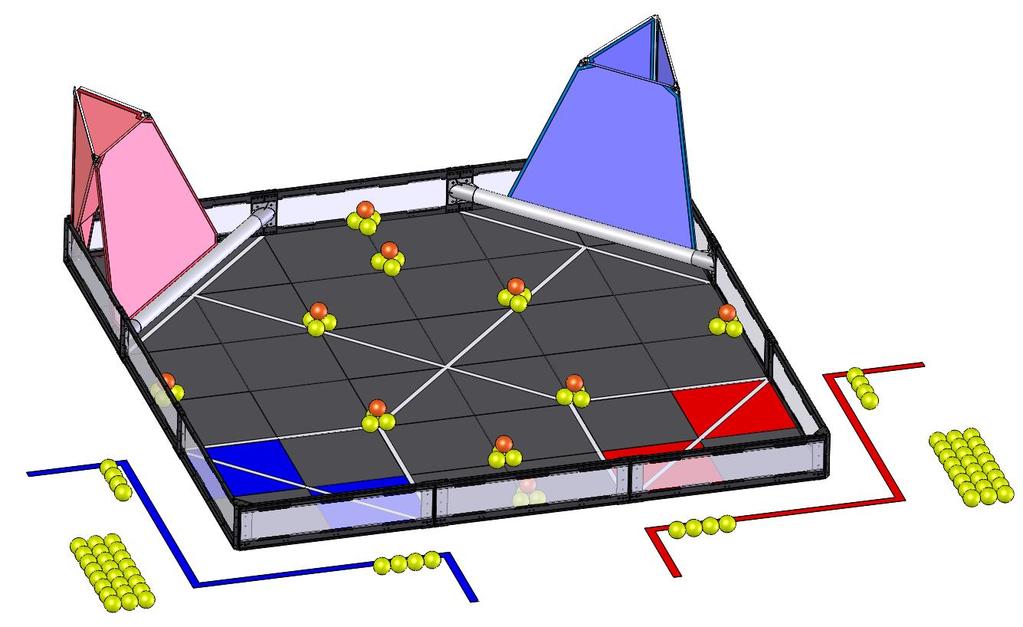
3 The game VX Robotics - othing But et is played on a 12 ft x 12 ft foam-mat, surrounded by a sheet-metal and polycarbonate perimeter. In two corners of this field there are the alliance goals, a High Goal made of netting and fiberglass rods, and a low goal partitioned by a piece of 3.5 diameter pipe. In the opposite corners a taped off zone signifies the Climbing Zone where teams may levate robots for extra points. Placed throughout the field are Balls and Bonus Balls, additional Balls are available for preload to be entered on the field during the match. For more details and specific game-play rules, please refer to the VX Robotics - othing But et competition manual. Page 3
 Grey, (2) Red, (2) Blue Tiles $ 189.")
4 VX Robotics Game Objects & Field Bill of Materials All these items are available for purchase from: Generic Field lements - Reuseable ach Year Part umber Price VRC Field Perimeter Frame & Hardware $ VRC Foam Field Surface - (36) Grey, (2) Red, (2) Blue Tiles $ VRC VXnet Field Controller $ Total Price $ 1, Official VX Robotics - othing But et Specific lements Part umber Price ALL Official VX othing But et Field & Game Objects $ (1) High Goal Kit (Red) (1) High Goal Kit (Blue) (100) Game Balls (12) Bonus Balls (4) Mesh Ball Bags (4) PVC Corner Connectors (2) PVC Corner Pipes (2) Field Corner Brackets All necessary assembly hardware Total Price $ Practice lements Part umber Price VRC Game lement Kit $ (25)Game Balls (3) Bonus Balls (1) Mesh Ball Bag VRC High Goal (Random Color) $ (1) High Goal Kit (random color) Page 4

5 This section will outline the specifications that are most important to teams designing a robot to compete in the VX Robotics othing But et. Though many of the critical dimensions are included in this section, it may be necessary to consult the separate assembly guide and 3D-CAD models of the field for an additional level of detail (if you can t find a dimension in the specifications, we include a FULL model of the field virtually measure whatever you need). Field components may vary slightly from event to event. This is to be expected; teams will need to adapt accordingly. It is good design practice to create mechanisms capable of accommodating variances in the field and game pieces. Page 5
6 Wall to Wall 1.27 Wall Width Wall to Wall Wall Height Field Critical Dimensions: - ~140.5" Square Wall - Wall, Inside " Wall Height " Wall Thickness Field Perimeter Specs Field Specs Rev1 VRC Sheet 1 of 8 Page 6


7 Hanging Zone Tape to Low Goal Bare Pipe 5.08 dge of High Goal to Pipe Wall to dge of High Goal Hanging Zone Tape to High Goal High Goal Opening Field Details Field Specs Rev1 VRC Sheet 2 of 8 Page 7

8 19.87 C L to C L C L to C L Typ C L toc L C L to C L C L to C L Typ Game Piece Locations Field Specs Rev1 VRC Sheet 3 of 8 Page 8
 Schedule 20 PVC.")
9 57.38 Bare Pipe 2.27 Floor to Bottom of Goal Pipe Bracket 3.50 Pipe 3.81 Floor to Bottom of Goal Pipe 7.38 Floor to Top of Goal Pipe 7.46 Floor to Top of Goal Pipe Bracket Goal Pipes are made of 3" (3.5" OD) Schedule 20 PVC. Pipe Specs Field Specs Rev1 VRC Sheet 4 of 8 Page 9


10 18.37 Goal Pipe dge to High Goal Opening 5.08 Goal Pipe dge to High Goal High Goal Specs Field Specs Rev1 VRC Sheet 5 of 8 Page 10

11 There are (94X) Balls and (10X) Bonus Balls on the Field. ach Ball weighs 0.115lbs 15%. Ball dimensions may vary by as much as 1/8". Ball Specs Field Specs Rev1 VRC Sheet 6 of 8 Page 11


12 There are (10X) strips of White 3/4" lectrical Tape running across the Field, as shown below. White 3/4" lectrical Tape Under Pipe White 3/4" lectrical Tape Under Pipe Tape Line Locations Field Specs Rev1 VRC Sheet 7 of 8 Page 12
 sets of (4X) Balls for Preload in each Alliance Station There are (24X) Balls in a bag")

13 The Balls are placed as follows before the start of each match There are (2X) sets of (4X) Balls for Preload in each Alliance Station There are (24X) Balls in a bag in each Alliance Station There are (10X) stacks of Balls placed around the Field, as shown. These stacks are centered on Tile junctions or seams Game Object Placement Field Specs Rev1 VRC Sheet 8 of 8 Page 13
.")


14 This section will detail the steps required to construct the competition field for the VX Robotics - othing But et. The field utilizes the VX Field Perimeter ( ). For specifications and instructions for assembling this frame, please refer to the separate VX Field Perimeter manual. Also refer to the separate low-cost field document, which provides lower cost options to teams not needing a full official competition field. The following tools are required for assembly of the official VX Robotics - othing But et field: 5/32 Allen Wrench Phillips Head Screw Driver Side Cutters or Scissors (for cutting zip ties) Sharp Knife or Razor Blade (for cutting foam tiles) Page 14

 Instructions for assembly are included with the VX Field Perimeter Instructions. 3.")
15 Driver Station (2X) (See ote 2) VX Field Perimeter (See ote 1) CROWD VIW otes: 1. Assemble the VX Field Perimeter (see separate VX Field Perimeter assembly instructions.) Position the Perimeter such that one side is "facing" the crowd. 2. Attach the Driver Station Posts as shown. (~1ft off Field Perimeter edge opposite of the crowd.) Instructions for assembly are included with the VX Field Perimeter Instructions. 3. Assemble the Foam Tiles inside the Perimeter. Refer to sheets 2-3 of this document for instructions Field VRC Sheet 1 of 16 Page 15

 Corner Tiles (C) Corner tiles have their interlocking tabs cut away on TWO adjacent edges.")
 dge Tiles () (2X) Red dge Tiles (2X) Blue dge Tiles (12X) Gray dge Tiles dge Tiles have their interlocking tabs cut away on O edge.")
16 Cut off 1/2 of each tab on this side Before assembling the Foam Tile Floor, some Tiles will need to be modified. There are 3 types of Tiles. IMPORTAT: BFOR MODIFYIG AY TILS, CHCK TO SUR YOUR ST OF TILS DS MODIFICATIO. Cut off 1/2 of each tab on this side Cut off 1/2 of each tab on this side Foam Tile modification has changed since previous years. Use a razor or sharp knife to remove only 1/2 of each tab as described below. (4X) Corner Tiles (C) Corner tiles have their interlocking tabs cut away on TWO adjacent edges. These will be used in the (4) corners of the Field. (16X) dge Tiles () (2X) Red dge Tiles (2X) Blue dge Tiles (12X) Gray dge Tiles dge Tiles have their interlocking tabs cut away on O edge. These will be used along the edges of the Field. (16X) ormal Tiles () ormal Tiles are unmodified. ormal Tiles are used on the "inside" of the Foam Tile Floor. ote: Older Tiles may need more than 1/2 of each outside tab removed. Letters in parenthesis are for reference on next page. Foam Tile Modification VRC Sheet 2 of 16 Page 16

17 A B C D F 1 C C C C Assemble Foam Tiles as shown above. The "smooth" side of the Tiles should be up, and the "textured" side down. The Tiles should be assembled "in-place", with the Field Perimeter. The "Blue" and "Red" dge Tiles should be placed as shown above. The grid-lines are for reference only. ote: The Tile grid can be labeled on a coordinate system horizontally with letters A-F and vertically with numbers 1-6. If you label the back of your Tiles in this manner it will make it easier to reassemble your Field later. Foam Tile Assembly VRC Sheet 3 of 16 Page 17

18 Image A 1/4-20 x 1/2" Screw (2X) (RMOV) Corner Gusset (RMOV) Corner Bracket 1/4-20 Wing ut (4X) Image B 1/4-20 x 1/2" Screw (4X) When assembling the Field Perimeter, (2X) Corner Brackets must be installed in the corners highlighted in Image A. The Corner Gussets from these locations are not used and can be stored elsewhere. Use (4X) 1/4-20 x 1/2" Screws and (4X) 1/4-20 Wing uts to secure each Corner Bracket as shown in Image B. Corner Bracket Installation VRC Sheet 4 of 16 Page 18

19 CROWD Once the Field Perimeter is in place, mark off the Alliance Stations using Red and Blue Tape as shown above. Do not close the Alliance Stations. The outside edges of the Alliance Stations should be in line with the edges of the corresponding colored tiles. Alliance Station Layout VRC Sheet 5 of 16 Page 19


20 There are (10X) strips of White 3/4" lectrical Tape running across the Field, as shown. The Tape Lines should be centered across the Tiles that they lay on or centered along the seam The tape forming the square should be entirely on the gray tiles IMPORTAT OT: DO OT stretch the Tape when applying to the Foam Tile Floor. For best results, smooth out any bubbles that form during application.. To prevent tape lines from being pulled up during competition, it is recommended that the ends of the tape are tucked into Tile seams. Pro-Tip: If the Tiles are to be used at multiple events, it is not necessary to remove the Tape. Simply cut the Tape at the Tile seams and note the order of the Tiles when they are stored. Tape Line Locations VRC Sheet 6 of 16 Page 20
 different Goal Pipe Brackets. ach type has either LFT or RIGHT printed as shown in Image C.")

21 Goal Pipe Bracket RIGHT Goal Pipe LFT #10 x 1/2" Self Tapping Screw Image A Image B Image C Use (1X) #10 x 1/2" Self Tapping Screw to attach each Goal Pipe to a Goal Pipe Bracket, as shown in Images A & B. A pilot hole may be drilled in the Goal Pipe to assit with screw insertion. There are (2X) different Goal Pipe Brackets. ach type has either LFT or RIGHT printed as shown in Image C. One Left Goal Pipe Bracket and one Right Goal Pipe Bracket are required for each Goal Pipe Assembly. Apply pressure to align Goal Pipe Bracket Properly aligned Goal Pipe Assembly Ground or other Flat Surface Image D Loosely attach a second Goal Pipe Bracket to the other end of the Goal Pipe. Apply pressure on the top of the Bracket to straighten and align the Goal Pipe Brackets as shown in Image D before securing with (1X) #10 x 1/2" Self Tapping Screw. (Optional): A 1/8" pilot hole may be drilled in the Goal Pipe to assist with screw insertion. Repeat for a total of (2X) Goal Pipe Assemblies. Goal Pipe Assembly VRC Sheet 7 of 16 Page 21

.")
22 1/4-20 Wing ut (4X) Goal Pipe Assembly Image A Image B 1/4-20 x 1/2" Screw (4X) Image C Slide the Lexan panel out of the Field Perimeter as shown in Image A. Then use (16X) 1/4-20 x 1/2" Screws and (16X) 1/4-20 Wing uts to mount (2X) Goal Pipe Assemblies to the Field Perimeter as shown in Images B & C (Wingnuts on the outside of the field). After Goal Pipe Assemblies have been installed, return each Lexan panel to its original position. Goal Pipe Installation VRC Sheet 8 of 16 Page 22
![1/4-20 x 1/2" Screw 1/4-20 ylock ut Image A Field Monitor Stand P/ 276-1572 Image B [Optional]: For events using Field Monitors.](/docs-images/86/93955165/images/23-0.jpg "Place the Field Monitor Stand with monitor attached in the center of the the wall as shown in Image A.")

23 1/4-20 x 1/2" Screw 1/4-20 ylock ut Image A Field Monitor Stand P/ Image B [Optional]: For events using Field Monitors. Place the Field Monitor Stand with monitor attached in the center of the the wall as shown in Image A. Use a 1/4-20 x 1/2" Screw and a 1/4-20 ylock ut to mount the Field Monitor Stand to the Field Perimeter as shown in Image B. Monitor can be mounted to the stand using the monitor mounting hardware included with the stand. ote: Field Monitor Mounting is OPTIOAL. vents may use field side displays. Field Monitor Installation VRC Sheet 9 of 16 Page 23
 different Fiberglass Rod Corner Connectors and (8X) lengths of Fiberglass Rod in locations indicated above. High Goal Assembly VRC 2015-2016 Sheet 10 of 16 Page 24")
24 Rod 4 Rod 4 Rod 3 Rod 7 Rod 6 Rod 8 Rod 5 Rod 8 Rod 5 Rod 2 Rod 1 Rod 2 There are a total of (2X) High Goals in VX othing But et - (1X) for Red Alliance and (1X) for Blue Alliance. There are (4X) different Fiberglass Rod Corner Connectors and (8X) lengths of Fiberglass Rod in locations indicated above. High Goal Assembly VRC Sheet 10 of 16 Page 24
25 Image A There are 4 different Rod Corner Connectors and 8 lengths of Fiberglass Rod. ach Corner Connector has a number printed on the Rod Receptacle as shown in Image A. ach Fiberglass Rod has a number labeled in 2 locations along its length. In ascending order, match the number on the Rod to the number on the Rod Corner Connectors. All Fiberglass Rods except both Rod 8's are assembled flat on the ground as shown in Image B. Rod 5 Step 1: Rod Rod 4 Rod 6 Rod 2 Rod 1 Image B Rod 7 Rod 5 Rod 3 Rod 4 High Goal Frame Assembly VRC Sheet 11 of 16 Page 25
26 Once the Goal is assembled flat, connect the free end of Rod 6 into the top gusset as shown in Image C. The High goal will now approximatly the correct shape. Step 2: Connect Image C Finally, both Rod 8's must be inserted into the remaining open connectors as shown in Image D. The High Goal is now the correct shape and the net can be put on. Step 3: Connect Image D High Goal Frame Assembly VRC Sheet 12 of 16 Completed Frame Page 26
 Rod 2. Step 7.")
27 Goal et Installation Image A Image B Image C Image D Step 4: Remove (2X) Rod 2 from the lower rod receptacle at the back of the Goal per Image A. Step 5: Orient the Goal et as shown in Image B. Bunch the "rear" part of the Goal et to create a thru-hole as shown in Images B and C. Step 6. Place the rear Rod Receptacle in the Goal et as shown in Image C. Then reattach (2X) Rod 2. Step 7. Bring the Goal et up around the Goal as shown in Image D. See next page. High Goal et Assembly VRC Sheet 13 of 16 Page 27

 Rod 8. Step 11.")
28 Image F Image G Image Image H Image I Image J Step 8. Bring the "front" of the Goal et above the horizontal Rod 4 as shown in Image. Step 9. Begin securing the Goal et to the Frame by wrapping the hook and loop fastener around the rods as shown in Images F and G. Step 10. Secure the Goal Opening Flaps to the Loop side fastener on the (2X) Rod 8. Step 11. Your High Goal is completely assembled, see Image J for reference. High Goal et Assembly VRC Sheet 14 of 16 Page 28


29 Image A Zip Tie Zip Tie Image B Place the (2X) High Goals onto the field as shown in Image A. Secure the High Goals using (4X) Zip Ties as shown in Image B. High Goal Installation VRC Sheet 15 of 16 Page 29
 piles of balls not adjacent to a wall may be placed in a random orientation, as long as the pile maintains the same shape and is approximately centered on the junction of")

30 Place the green Balls and orange Bonus Balls on the Field in the positions shown. Please note that the six (6) piles of balls not adjacent to a wall may be placed in a random orientation, as long as the pile maintains the same shape and is approximately centered on the junction of the foam field tiles. (i.e. the piles may rotated from what is depicted above) Place (24X) green Balls in a Bag located in each driver station. Tip: For easy transportation and storage, High Goals can be disassembled and stored inside their respective Goal Pipes. Refer to the othing But et Game Manual for more details, including all official rules and regulations. Also, use the 3D CAD model of the othing But et Field for additional details not shown in the Field Drawings Field VRC Sheet 16 of 16 Page 30
Field Specs & Assembly Instructions
 VEX Robotics Sack Attack Field Specs & Assembly Instructions 4/13/2012 Copyright 2012. VEX Robotics Inc. VEX Robotics Sack Attack A Introduction A P P E N D I X Game Field This document will provide detailed
This document will provide detailed specifications, BOM information, and assembly instructions for the Official Competition Field.
 This document will provide detailed specifications, BOM information, and assembly instructions for the Official Field. Teams who do not need an official field should refer to the separate low-cost field
This document will provide detailed specifications, BOM information, and assembly instructions for the Official Competition Field.
 This document will provide detailed specifications, BOM information, and assembly instructions for the Official Competition Field. Teams who do not need an official field should refer to the separate low-cost
This document will provide detailed specifications and a bill of materials (BOM) for the Official Competition Field.
 for the Official Competition Field.") Introduction This document will provide detailed specifications and a bill of materials (BOM) for the Official Competition Field. Please note that this field utilizes the VEX IQ Challenge Full Field Perimeter
Introduction This document will provide detailed specifications and a bill of materials (BOM) for the Official Competition Field. Please note that this field utilizes the VEX IQ Challenge Full Field Perimeter
VEX IQ Challenge - Highrise. Field Appendix. Page 1. Copyright VEX Robotics Inc. v
 Field Appendix Page 1 Introduction This document will provide detailed specifications, a bill of materials (BOM), and assembly instructions for the Official Competition Field. Please note that this field
Closet System Installation Manual
 Closet System Manual Thank you For choosing our Custom Closet Collection to fit all your needs Closets come fully assembled to make your project an enjoyable and satisfying experience. With quality Custom
RAMPAGE P R O D U C T S. INSTALLATION INSTRUCTIONS BRONCO ZIPPER FASTRACK TOP PART #984xx BRONCO TOOLS REQUIRED
 RAMPAGE P R O D U C T S 84 (+/- 1/4 ) INSTALLATION INSTRUCTIONS BRONCO ZIPPER FASTRACK TOP PART #984xx BRONCO 1966-1977 TOOLS REQUIRED 3/8 WRENCH 7/16 WRENCH ½ WRENCH #2 PHILLIPS SCREWDRIVER 1/8 DRILL
Aeon AcousticPro UHD Series
 Aeon AcousticPro UHD Series EDGE FREE Fixed Frame Sound Transparent Projection Screen User s Guide Product Description: The Aeon AcousticPro UHD Series is a fixed frame projection screen that uses Elite
Frameless Fixed Panel Slider
 INSTALLATION INSTRUCTIONS Frameless Fixed Panel Slider QCI-5279 SINGLE ROLLER WITH ANTI-JUMP DOUBLE ROLLERS QCI5279 Rev Page Certified 08/09/6 Tools: To install your New Shower Enclosure, you may need
C-Series & S-Series Classic Frame with Transom (Single or Pair)
") 1. TOOLS REQUIRED Tape measure 6' magnetic level 3' magnetic level Safety Glasses Screw gun #2 Screwdriver tip #3 Screwdriver tip Philips Head screwdriver (Used to move frame on wall using oval slots on
1. TOOLS REQUIRED Tape measure 6' magnetic level 3' magnetic level Safety Glasses Screw gun #2 Screwdriver tip #3 Screwdriver tip Philips Head screwdriver (Used to move frame on wall using oval slots on
DIY Field Guide ANDYMARK, INC.
 ANDYMARK, INC. Intro For the 2014-2015 FTC Game Cascade Effect, teams can purchase official field hardware from AndyMark, or they can build do-it-yourself (DIY) versions of the same hardware. The competitions
re3d Assembling Gigabot: "Flatpack"
 re3d Assembling Gigabot: "Flatpack" Your Gigabot was assembled, calibrated, tested, and taken apart for shipping purposes. All you need to do is reassemble it, and you're ready to go! Written By: Chris
Hatchback Wing Riser Kit
 Hatchback Wing Riser Kit 2015-06-11 Thank you for purchasing this PERRIN product for your car! Installation of this product should only be performed by persons experienced with installation of aftermarket
MKPLAY VAULT MINI TRAMPOLINE SERIES
 MKPLAY VAULT MINI TRAMPOLINE SERIES 55 INCH (4.5FT) TRAMPOLINE WITH SAFETY NET ENCLOSURE Weight Limit 100lbs (45kg) Person Limit 1 Persons Age Limit 3-6 years 1 TABLE OF CONTENTS Parts List Trampoline
INSTALLATION GUIDE. TRANZFORM Sound TRANZFORM Space
 INSTALLATION GUIDE TRANZFORM Sound TRANZFORM Space Cornell Iron Works, Inc. 100 Elmwood Ave. Crestwood Industrial Park Mountain Top, PA 18707 Phone: 800.233.8366 or 570.474.6773 Fax: 800.526.0841 INSTALLATION
Owner s Guide. Roller Shades. Clutch Operated Standard Shades
 Owner s Guide Roller Shades Clutch Operated Standard Shades CONTENTS Product View...4 Introduction...5 Getting Started...5 Tools And Fasteners Needed...5 Install The Mounting Brackets...6 Install The
Installation And Care Instructions. Vertical Honeycomb Shades
 Installation And Care Instructions Vertical Honeycomb Shades Rev 5/2013 Table Of Contents Getting Started... 3 Parts Overview... 4 Materials Required... 5 Tools Required... 6 Outside Mount Installation...
Parts Included: Tools Required: Canvas Office Landscape Interiors Off Module 90 Connector Kit Installation and Disassembly for Recycling Instructions
 Y Parts Included: Canvas Office Landscape Interiors Off Module 90 Connector Kit Installation and Disassembly for Recycling Instructions FT127.A N Shim A Light Seal B Foam Light Seal C G H Double-Face Tape
Box Track INSTALLATION INSTRUCTIONS
 Box Track INSTALLATION INSTRUCTIONS BOX TRACK Recommended Tools Level Tape Measure Pencil Drill with 1/8, and 1/4, Drill Bits, Phillips Bit and Slotted Bit Socket Wrench with 9/16 Socket 9/16 and 5/8 Wrench
Fortress Fe Posts must always be secured to the deck framing. Fortress Fe Posts should never be attached to only the deck boards.
 Installation Instructions for FortressCable H-Series Stair Panels with Simplified Stair Bracket SSB-05 and Fe Posts It is the responsibility of the installer to meet all code and safety requirements, and
Assembly Instructions
 Selling Station Assembly Instructions View from above without top A B C D Rounded finished corners on A & D Square unfinished 3-sides on B & C Selling Station Components (2) 2' x 6' Side s Have a channel
Tools Required. Bench Hardware. Bench Parts. Planter Hardware. Planter Parts. BENCH/PLANTER INSTALLATION GUIDELINES for
 Arbor Collection / Harvest Collection / Terra Collection Page 1 Please read all instructions completely before starting any part of the installation. Each AZEK and Kit comes complete with all hardware,
TABLE OF CONTENTS REQUIRED TOOLS
 TABLE OF CONTENTS SECTION SECTION TITLE PAGE NO. 1 2 3 4 5 Assembling Mounting Structure Installing Bicycle Supports Mounting Rack to Wall Adding Sections Customizing Rack Configuration REQUIRED TOOLS
Kwik-Lock. Installation Instructions. Attention Dealers: Please give this owners manual to the customer when the product is delivered.
 Serving the Truck & Trailer Industry Since 1944 Installation Instructions Attention Dealers: Please give this owners manual to the customer when the product is delivered. Call 800-535-9545 www.aeroindustries.com
Walk-in Configurations
 Walk-in Configurations Includes Wall-to-Open, Corners, and Corner Rounder Bars INSTALLATION INSTRUCTIONS Tools needed: Tape measure, level, pencil, #2 Phillips head screw driver or power drill with a 6"
Oxford Stalls Installation Instructions
 Oxford Stalls Installation Instructions RAMM Horse Fencing and Stalls 13150 Airport Hwy. Swanton, OH 43558-9615 1-800-434-8456 Rev. 8/15/17 Before You Start Typical stall sizes are 10 x 10, 12 x 12 or
V nyl Gazebo truct c it Assembly Instr ons
 V nyl Gazebo Vi Assembly Instr ct tr t u ru ons ct c i ti Pre-assembly Instructions A C B #1 - Site properly prepared. 4" - 6" clean stone 9 linear blocks 2" x 8" x 16" C C A A B B #1a - 12" sauna tubes,
Fortress Fe Posts must always be secured to the deck framing. Fortress Fe Posts should never be attached to only the deck boards.
 Installation Instructions for Fortress Horizontal Cable Panel System with UB-05 Brackets and Fe Posts It is the responsibility of the installer to meet all code and safety requirements, and to obtain all
AFCO-Rail Post INSTALLATION INSTRUCTIONS AFCO-RAIL POST
 AFCO-Rail Post INSTALLATION INSTRUCTIONS TOOLS REQUIRED: Drill Bits (for the appropriate fastener) Drill (with adjustable clutch, recommended) Level String Line Tape Measure Tools to install fasteners
INSTALLATION AND CARE INSTRUCTIONS
 INSTALLATION AND CARE INSTRUCTIONS Vertical Applications Honeycomb Shades 52 C8-10-3401 Rev 2/14 CONTENTS Introduction...2 Before You Begin...3 Vertical Application Parts Overview...4 Materials Required...5
Gared Pro-S Portable Backstop
 Models: 9616 & 9618 Installation, Operation and Maintenance Instructions Please read all instructions before attempting installation or operation of these units SAVE THESE INSTRUCTIONS FOR FUTURE USE PUBLICATION
FORD TRANSIT VAN PANELS (2015+) 130 /148 WHEEL BASE LOW ROOF INSTALLATION INSTRUCTIONS
 130 /148 WHEEL BASE LOW ROOF INSTALLATION INSTRUCTIONS") FORD TRANSIT VAN PANELS (2015+) 130 /148 WHEEL BASE LOW ROOF INSTALLATION INSTRUCTIONS RECOMMENDED TOOLS -Phillips #4 screwdriver -Phillips #3 screwdriver -Knife or scissors (optional) BEFORE BEGINNING
FORD TRANSIT VAN PANELS (2015+) 130 /148 WHEEL BASE LOW ROOF INSTALLATION INSTRUCTIONS RECOMMENDED TOOLS -Phillips #4 screwdriver -Phillips #3 screwdriver -Knife or scissors (optional) BEFORE BEGINNING
Connect Transit Shelter
 Tools Required *denotes special tools required Connect Shelter, 8ft Connect Shelter, 12ft *Soft, non abrasive protective surface such as a furniture blanket *Source of compressed air (for thorough dust
Figure A. Figure B. Figure C. Figure D
 Xsite 1 Power/Data Tile and Components Tools Required Tape Measure Cordless Drill/Driver #2 Phillips Screw driver bit Rubber Mallet Flat Blade Screwdriver Figure A Hardware Required Provided as shown Installation
Showpiece Cabinet Integrated Stand For 32" - 52" LCD HDTV
 Showpiece Cabinet Integrated Stand For 32" - 52" LCD HDTV Installation and Assembly Instructions 2009 Incredible Technologies Inc. Version 0109 Showpiece Cabinet Integrated Stand for 32" - 52" LCD HDTV
compile system INSTALLATION GUIDE Updated January 2019
 INSTALLATION GUIDE Updated January 09 compile system Table of Contents Panels 0 Quick Connect Clips 0 Lock Clips 0 Panel Trims 0 Privacy Glass 0 Post Base Covers 04 Electrical 04 Power Distribution Harness
ZEN AND THE ART OF FIELD CONSTRUCTION
 A MANUAL OF CONSTRUCTION TIPS AND TECHNIQUES FOR BUILDING THE 2009 FTC PLAYING FIELD. This manual should be used in conjunction with the detailed field drawings. Document Revision History Rev Date Changes
CONTENTS TOOL LIST U P S I D E I N N O V A T I O N S, L L C RAMP AND STEP SYSTEM ASSEMBLY INSTRUCTIONS. Revised: June 2013
 U P S I D E I N N O V A T I O N S, L L C RAMP AND STEP SYSTEM ASSEMBLY INSTRUCTIONS TOOL LIST Required Tools: - Reciprocating Saw with Metal Cutting Blade - Drill - 7/16 Drill Bit for Metal Drilling -
Triple Bypass System
 Triple Bypass System ASSEMBLY INSTRUCTIONS TRIPLE BYPASS SYSTEM Recommended Tools Drill with 1/4 Drill Bit and Phillips Screw Bit 7/16 Combination Wrench Socket Wrench with 7/16 and 9/16 Socket Level Tape
PARTS INCLUDED IN FIXED STAIR CABLE RAIL KIT:
 175 SERIES FIXED STAIR CABLE RAIL - INSTALLATION INSTRUCTIONS PARTS INCLUDED IN FIXED STAIR CABLE RAIL KIT: FIXED STAIR TOP RAIL (1) A FIXED STAIR BOTTOM RAIL (1) B D UPPER SADDLE BRACKET (1) C BRACKET
Gared Pro Portable Backstop
 Models: 5016, 5017, & 5018 Installation, Operation and Maintenance Instructions Please read all instructions before attempting installation or operation of these units PUBLICATION NO. 551754436 SAVE THESE
SETUP GUIDE FOR THE HANGING MINIBAY and SUPERBAY Golf Simulator Screen Systems.
 SETUP GUIDE FOR THE HANGING MINIBAY and SUPERBAY Golf Simulator Screen Systems www.allsportsystems.com Page 2 of 15 Rev 3/1/2018 Table of Contents INTRODUCTION 4 What s Included: 5 Additional Items Needed:
Frameless Fixed Panel Slider QCI5279
 Frameless Fixed Panel Slider QCI5279 F AB GLASS AND MIRROR www.fabglassandmirror.com Call: +1 888-474-2221 Fax: (614)-334-4919 Office Timing: 8:30-18:00 EST info@fabglassandmirror.com Frameless Fixed Panel
ClearSpan Hydroponic Table Kit
 ClearSpan Hydroponic Table Kit Hydroponic Table Kit (The 109314 (4' x 16') model is shown.) Designed to grow healthy plants without soil using mineral-nutrient solutions. 2009 ClearSpan All Rights Reserved.
Cabinet is 90% assembled, all you need to do is to attach the legs, lay the glass top on the cabinet, connect the faucet, drains & ptrap.
 Things you might need for the installation: vessel sink, plumber's putty(home depot), liquid nails(home depot), Bucket silicone caulk(home depot), Putty knife Plumber's putty Pipe wrench Channel-lock pliers
The Festival Assembly Instructions
 The Festival Assembly Instructions Toll Free: 866.768.8465 Hours: 9-5 Monday-Friday EST www.homeplacestructures.com Package ships as shown CONTACT INFORMATION: HomePlace Structures 301 Commerce Drive New
Frameless Bypass Slider
 INSTALLATION INSTRUCTIONS Frameless Bypass Slider QCI-5301 Heavy Glass Bypass Slider with Exposed Rollers QCI5301 Rev 0 Page 1 Certified 11/1/2016 Tools: To install your New Shower Enclosure, you may need
Fixed Wall Arm. Installation Guide. Part number Rev E 2012 PolyVision Corporation All rights reserved
 Fixed Wall Arm Installation Guide Part number 2002003-001 Rev E 2012 PolyVision Corporation All rights reserved Table of contents Important Safety Instructions... 3 Overview... 4 Important considerations...
The Queen Quilter Professional Quilters Kit Frame
 The Queen Quilter Professional Quilters Kit Frame Assembly Instructions Table of Contents: Before you begin......................... Pg. 2 Wood parts............................. Pg. 3 Hardware..............................
Setup. The Faraday Cage is available in two types of configurations. Cage for mounting to a full perimeter enclosure on series tables.
 Faraday CageSetup, 2017 Setup The Faraday Cage is available in two types of configurations. Cage for mounting to a full perimeter enclosure on 63-500 series tables. Cage with a base plate for use on a
Installation Instructions for. Handrail Component System
 Handrail STEP-BY-STEP Installation Instructions for Handrail Component System Rise in Inches Run in Inches 8 8.5 9 9.5 10 10.5 11 11.5 12 12.5 13 13.5 14 14.5 15 8.5 47 45 43 42 40 39 38 36 35 34 33 32
Model #SH & CH SH Pine CH Naturaline
 Model #SH304-101 & CH304-101 Assembly Manual SH304-101 Pine CH304-101 Naturaline Component Parts A 2 ea. Angled Rail - 2 x 4 x 107-1/8" B 1 ea. Center Angled Rail - 2 x 4 x 107-1/8" C 9 ea. Rock Board
INSTRUCTIONS High Tech II Unit Assembly
 INSTRUCTIONS High Tech II Unit Assembly The following instruction is a guideline, illustrating suggested methods, assembly sequence, and tool selection. Actual assembly may vary by each situation. Careful
How To Measure Your Finished Opening
 3000 Series Bifold Doors How To Measure Your Finished Opening MEASURE FROM RIGHT TO LEFT 2 PLACES (WIDTH) MEASURE FROM TOP TO BOTTOM 2 PLACES (HEIGHT) Tools Required for Assembly: Tools Needed: Phillips
Owner's Manual & Assembly Instructions
 Owner's Manual & Assembly Instructions TQ01 Universal Attic Kit Model No. AT101 IMPORTANT: Before you start, remove Owner's Manual & Assembly Instructions from main carton of your storage building and
Frameless Inline Door With Return QCI5263
 INSTALLATION INSTRUCTIONS Frameless Inline Door With Return QCI5263 WALL MOUNT HINGES FRAMELESS DOOR / PANEL / RETURN PANEL QCI5263 REV. 0 Page 1 Certified 06/17/2016 Parts List with wall mount hinges
RPMSP Series Installation Guide
 RPMSP Series Installation Guide Contents 1. Overview... page 1 2. Unpacking the Projector...2 3. Projector Configuration...2 4. Projector Throw Distance and Mounting...9 5. Projection Lens Focus...9 6.
LIGHT FIXTURES MUST BE COMPLETELY INSTALLED PRIOR TO CEILING CONSTRUCTION
 CAUTION: BEFORE BEGINNING INSTALLATION REVIEW LAYOUT DRAWINGS, AND SHIPMENT. MAKE SURE ALL LIGHT S AND MATERIALS ARE ON SITE AND READILY ACCESSIBLE. IF ANY ICON MATERIALS ARE MISSING, CONTACT ICON INTERNATIONAL
CABANA / PAVILION ASSEMBLY ALUMINUM FRAME MODELS
 Assembled cabanas are large & heavy. Assemble at place of use. CABANA / PAVILION ASSEMBLY ALUMINUM FRAME MODELS Step 1 CAUTION: To avoid damage to the finish of your Cabana frame, prepare a smooth, non-scratch
Video Wall Installation Instructions 2W X 3H, 3W X 3H
 Video Wall Installation Instructions 2W X 3H, 3W X 3H www.microndisplaysolutions.com Table of Contents Important Safety Instructions... 3 Configuration... 4 Package Contents, included and optional items...
Assembly Instructions
 InTandem Table System November 20 InTandem Table System - Worksurface #4 x/" 4 wood screw power beam Tools Provided T-0 Extended Torx Driver T-25 Torx Driver Additional Tools Required Soft protective
PORTA TRAK OWNERS MANUAL
 PORTA TRAK OWNERS MANUAL Table of Contents: I. Rail and Frame Parts List Please read the instructions thoroughly before setting up the Porta Trak. Carefully follow how to spring the bed step by step. II.
Installing flat panels on the MPL15 wall mount
 Installing flat panels on the MPL15 wall mount The MPL15 (DS-VW775) is a full-service video wall mount that can accommodate tiled LCD panels with up to a 400 x 400 mm VESA pattern in portrait and landscape
Installation Manual For ToddPod Outdoor Shower Enclosures
 Installation Manual For ToddPod Outdoor Shower Enclosures Contact us at 888-545-9763 or email us at office@toddpod.com with any questions during the installation process. Our service team is available
PowerLock. Installation Instructions. Attention Dealers: Please give this owners manual to the customer when the product is delivered.
 Serving the Truck & Trailer Industry Since 1944 FOR Attention Dealers: Please give this owners manual to the customer when the product is delivered. Call 800-535-9545 www.aeroindustries.com Indianapolis,
Triplex Instructions for Packing and Unpacking
 2-8-8-2 Triplex Instructions for Packing and Unpacking It is recommended that you review all these instructions before removing the engine or tender from the poly foam container. www.mthtrains.com Table
TOOL LIST FOR TAILGATE HIDDEN LATCH & LINK ASSY FOR FORD FLARESIDE TRUCKS
 TOOL LIST FOR TAILGATE HIDDEN LATCH & LINK ASSY FOR 53-87 FORD FLARESIDE TRUCKS Vise Grip Clamps C-clamps Sharpie Marker Ball Peen Hammer Center Punch 3/8 or 1/2 Drill 5/32, 7/32, 9/32, and 3/8 Drill Bits
GROWING BETTER THROUGH DESIGN. 6ft Lean-To LEAN-TO. Assembly Instructions 04/02
 GROWING BETTER THROUGH DESIGN 6ft Lean-To LEAN-TO Assembly Instructions 04/02 6ft Lean-To Greenhouse Base Plan Introduction/Tools/Contents / / Contents This is a copy of our Lean-To greenhouse base plan.
IMPORTANT!!! ASSEMBLY ASSEMBLY INSTRUCTIONS. (Internal Dimensions)
") ASSEMBLY ASSEMBLY INSTRUCTIONS (Internal Dimensions) Ent Spec Edition Ltr v-0- Overall dimensions including base: 7. L x 9 W x 0 H cms 97.5" L x 7" W x 8.7" H IMPORTANT!!! Please read these instructions
ASSEMBLY ASSEMBLY INSTRUCTIONS (Internal Dimensions) Ent Spec Edition Ltr v-0- Overall dimensions including base: 7. L x 9 W x 0 H cms 97.5" L x 7" W x 8.7" H IMPORTANT!!! Please read these instructions
Installation Instructions
 Contents Page General Information and Installer Tips.......... 2 Panels & Posts............................. 3 Enclosure Description..................... 4 Hinge Door Hardware................... 4-5 Step-by-Step
Contractors Rack Assembly and Installation Instructions
 Part # 18601 & 16601 Contractors Rack Assembly and Installation Instructions 4751 Littlejohn St. Unit A, Baldwin Park, CA 91706 Page 1 of 12 11/13/08 Thank you for purchasing the Paramount Restyling Contractors
The Portable Open Source 3D Printer
 http://web.archive.org/web/201502142011/http://www.tantillus.org/build_3.html Page 1 of 12 captures 12 Oct 12 - Feb 15 The Portable Open Source 3D Printer Home Start Case X/Y Axis Extruder Z Axis Electronics
This instruction manual is an in-depth look and explanation of how to assemble and install the Murphy Bed properly and efficiently.
 This instruction manual is an in-depth look and explanation of how to assemble and install the Murphy Bed properly and efficiently. Don t be put off by the size of the instruction manual as the large diagrams
ZEN AND THE ART OF FIELD CONSTRUCTION. A manual of construction tips and techniques for building the Get Over It! playing field.
 ZEN AND THE ART OF FIELD CONSTRUCTION A manual of construction tips and techniques for building the Get Over It! playing field. Release Date 9/11/2010 TABLE OF CONTENTS Zen and the Art of Get Over It Field
METALWORKS Concealed. Installation Instructions
 METALWORKS Concealed Installation Instructions 1. GENERAL 1.1 Product Description MetalWorks Concealed ceilings consist of perforated and unperforated panels that are downward accessible, and are designed
BioPrism Solid Surface
 Please read all instructions before installing products. These instructions are intended for use with InPro s standard toilet partitions, which include 58 high doors and wall panels, when deviating from
LCD LIFT Flat Panel Display System Installation Manual. Table of Contents
 LCD LIFT Flat Panel Display System Installation Manual Table of Contents Page Installation Overview... 2 Trim Ring Installation... 3 LCD Lift Installation....4 Actuator Switch Installation.5 Top Plate
General Array Layout Sketch
 General Array Layout Sketch Cold TO Panels Hot FROM Panels OR Cold TO Panels Hot FROM Panels 1 Introduction This document describes how to install EZ series panels. The EZ series panels are designed to
Frameless Bypass Slider
 INSTALLATION INSTRUCTIONS Frameless Bypass Slider QCI-5301 3/8 or 1/4 Glass Bypass Slider with Exposed Rollers QCI5301 Rev 1 Page 1 Certified 6/5/2017 Tools: To install your New Shower Enclosure, you may
PowerLock. Installation Instructions. Attention Dealers: Please give this owners manual to the customer when the product is delivered.
 Serving the Truck & Trailer Industry Since 1944 FOR Attention Dealers: Please give this owners manual to the customer when the product is delivered. Call 800-535-9545 www.aeroindustries.com Indianapolis,
MONKEY BARS OVERHEAD RACK INSTALLATION
 MONKEY BARS OVERHEAD RACK INSTALLATION Thank you for purchasing the New Monkey Bars Overhead storage rack. The most innovative overhead rack on the market WARNING THE PROPER INSTALLATION OF THIS STORAGE
INSTALLATION AND CARE INSTRUCTIONS
 INSTALLATION AND CARE INSTRUCTIONS Vertical Applications Honeycomb Shades CONTENTS Introduction...2 Before You Begin...3 Vertical Application Parts Overview...4 Materials Required...5 Tools Required...6
P.O. Box 8400 Green Bay, WI (920)
") P.O. Box 8400 Green Bay, WI 54308-8400 (920) 468-2165 Change Notice No. 112 Implemented By: KI-Pembroke Notification By: Scott Vissers Date: 03/15/10 Component Product Title: Series XXI Lateral Filing
P.O. Box 8400 Green Bay, WI 54308-8400 (920) 468-2165 Change Notice No. 112 Implemented By: KI-Pembroke Notification By: Scott Vissers Date: 03/15/10 Component Product Title: Series XXI Lateral Filing
BABY WOLF LOOM. Assembly Instructions for Knocked-Down Looms
 BABY WOLF LOOM Assembly Instructions for Knocked-Down Looms BEFORE YOU BEGIN Please read through the directions before beginning to assemble your loom. Unpack the loom parts carefully. Do not throw away
EmagiKit. Privacy Pod Plus. Quiet. Easy. Affordable. INSTRUCTIONS ASSEMBLY
 EmagiKit Privacy Pod Plus Quiet. Easy. Affordable. INSTRUCTIONS ASSEMBLY DIMENSIONS AND COMPONENTS 47 47 Ceiling Unit 2-B 2-L 2-R Glass Door Corner Trim Door Handle 90 Adjustable Height Work Surface 1-B
Franklin Mills Stackable Movable Lateral Instructions
 Franklin Mills Stackable Movable Lateral Instructions Table of Contents: Table of contents...1 Tools Required...2 Stationary Shelving Assembly...3-7 Mobile Shelving Assembly...8-16 Rail Assembly...8-11
1 PREPARE HEADER AND ROUGH OPENING
 CONTENTS. HEADER & TRACK ASSEMBLY. END BRACKET PLAIN 3. FLOOR PLATE.. 8. 4. SPLIT STUD 6 5. CARRIER (987) 6. QUICK RELEASE PLATE (960) 7. DOOR GUIDE SET (9883) 3. 4. 7. 8. BUMPER KIT (988) 9. #8 X 3/4
INSTALLATION INSTRUCTIONS
 INSTALLATION INSTRUCTIONS For Wallbed models: Do-It-Yourself BOOKLET #C90 WARNING! ALL MURPY/WALLBED SYSTEMS CONTAIN STORED ENERGY. FAILURE TO USE AND FOLLOW THESE INSTRUCTIONS DURING THE INSTALLATION
Installation Instructions Standalone or continuous run configurations - 2 JOINER ALIGNERS - 2 JOINING BRACKETS - 4 HEX BOLTS
 - 2 JOINER ALIGNERS - 2 JOINING BRACKETS - 4 HEX BOLTS TruGroove Drywall A3 MOUNTING Ceiling INSTALLATION System Overview These instructions review how to install trimless drywall versions of TruGroove
Fortress Fe Posts must always be secured to the deck framing. Fortress Fe Posts should never be attached to only the deck boards.
 Installation Instructions for FortressCable H-Series Cable Panel System With UB-05 Brackets and Fe Posts It is the responsibility of the installer to meet all code and safety requirements, and to obtain
Qwik-Fence Installation Instructions
 Qwik-Fence Installation Instructions 1 Tools Required The following installation instructions should be used as a guide for installing Folding Guard Qwik-Fence Partitions. Good common sense and appropriate
NUMBER OF HORIZONTALS REQUIRED FOR 2 ON CENTER SPACING.
 K WIK FRAME ASSEMBLY INSTRUCTIONS NUMBER OF HORIZONTALS REQUIRED FOR 2 ON CENTER SPACING. APPROXIMATE DOOR LEAF WEIGHT (LBS.) WITH 29 GAUGE STEEL PANEL ALL PACK AGES INCLUDE #235 STEEL GIRT 2 FT. ON CENTER
*D-1030* 1 PARTS CHECK 8 REVERSING INSTRUCTIONS F-XX-C & XX-C D Customer Service. Installation Instructions. Exit Devices
 *D-1030* D-1030 F-XX-C & XX-C Exit Devices Installation Instructions 8 REVERSING INSTRUCTIONS TO REVERSE THE HANDING OF A (F)XX-C DEVICE NOTE: TO REVERSE TRIM, REFER TO SEPARATE INSTALLATION SHEETS. 1
ED1300/1300F SERIES CONCEALED VERTICAL ROD DEVICE INSTALLATION INSTRUCTIONS
 ED1300/1300F SERIES CONCEALED VERTICAL ROD DEVICE INSTALLATION INSTRUCTIONS Ver.2 1300 SERIES CONCEALED VERTICAL ROD DEVICE Top Strike Latch Screws Strike Screws Release Plunger Top Latch Plunger Screws
POP PLUS / SPIDER SET-UP INSTRUCTIONS
 POP PLUS / SPIDER SET-UP INSTRUCTIONS 1 Place system frame on floor with screws indicating top. Expand upwards & outwards and secure frame connectors. Pop-Up display systems are made to be set-up and taken
Dubnium 11 Installation Instructions & Parts List
 Dubnium 11 Installation Instructions & Parts List Illustration Dubnium, H1 Handle Right Hand: Open Out Page 1 of 25 IMPORTANT This shower screen / enclosure must be installed by suitably qualified individuals.
TREX TRANSCEND RAILING
 RAILING NOTES:» RAILINGS ARE DESIGNED TO BE INSTALLED OVER THE DECKING FRAME OR ON INSIDE OF RIM JOIST. NOTCHING OF PRESSURE-TREATED POSTS OR POSTS INSTALLED ON OUTSIDE OF RIM JOIST IS NOT ALLOWED.» All
10 x 12 home air pro. VISIT LINK BELOW FOR INSTALL VIDEO
 in-ground installation instructions & user guide 10 x 12 home air pro VISIT LINK BELOW FOR INSTALL VIDEO https://www.maxairtrampolines.com/pages/support-information-videos Page 2 TABLE OF CONTENTS Materials,
Version 2016_1.1 VICTORIAN ASSEMBLY INSTRUCTIONS. Victorian Vi-23, 34, 36
 Version 2016_1.1 VICTORIAN ASSEMBLY INSTRUCTIONS Victorian Vi-23, 34, 36 PRODUCT INFORMATION Dear customer, Thank you for buying a high-quality aluminium greenhouse. REMARKS The drawings in these instructions
Installation Instructions for. Before You Begin TOOLS REQUIRED
 Composite Railing System STEP-BY-STEP Installation Instructions for Spectrum Composite Railing Virtually maintenance free 20-year warranty EverNew Spectrum Railing system is designed to work with a number