Instruction Manual book
|
|
|
- Charity Sherman
- 6 years ago
- Views:
Transcription


1 Instruction Manual book ITEM CODE: BH50. SPECIFICATION Wingspan : 1,600 mm in. Length : 1,230 mm in. Weight : 2.5 kg 5.5 Lbs. Radio : 06 channels. Servo : 07 servos. Electric Motor : ( 02pcs ) AXI 2814/12. Battery: 3 CELLS-LI-POLY 11.1V-5000 ma.h-20 c. Propeller : ( 02pcs )10 x 6 Speed control : ( 02pcs ) : 40 A. Made in Vietnam.
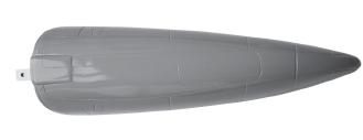
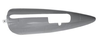
2 This instruction manual is designed to help you build a great flying aeroplane. Please read this manual thoroughly before starting assembly of your MOSQUITO MK VI. Use the parts listing below to identify all parts. WARNING. Please be aware that this aeroplane is not a toy and if assembled or used incorrectly it is capable of causing injury to people or property. WHEN YOU FLY THIS AEROPLANE YOU ASSUME ALL RISK & RESPONSIBILITY. If you are inexperienced with basic R/C flight we strongly recommend you contact your R/C supplier and join your local R/C Model Flying Club. R/C Model Flying Clubs offer a variety of training procedures designed to help the new pilot on his way to successful R/C flight. They will also be able to advise on any insurance and safety regulations that may apply. TOOLS & SUPPLIES NEEDED. Thick cyanoacrylate glue. 30 minute epoxy. 5 minute epoxy. Hand or electric drill. Assorted drill bits. Modelling knife. Straight edge ruler. 2mm ball driver. Phillips head screwdriver. 220 grit sandpaper. 90 square or builder s triangle. Wire cutters. Masking tape & T-pins. Thread-lock. Paper towels. PARTS LISTING. FUSELAGE ASSEMBLY (1) Fuselage. WING ASSEMBLY (1) Right wing half with pre-installed aileron. (1) Left wing half with pre-installed aileron. Tail section assembly (1) Vertical stabilizer with preinstalled rudder. (1) Horizontal stabilizer with preinstalled elevator halves. Some more parts. HARDWARE PACK COWLING. Landing gear... SUGGESTION. To avoid scratching your new airplane, do not unwrap the pieces until they are needed for assembly. Cover your workbench with an old towel or brown paper, both to protect the aircraft and to protect the table. Keep a couple of jars or bowls handy to hold the small parts after you open the bag. NOTE. Please trial fit all the parts. Make sure you have the correct parts and that they fit and are aligned properly before gluing! This will assure proper assembly. MOSQUITO MK VI ARF is hand made from natural materials, every plane is unique and minor adjustments may have to be made. However, you should find the fit superior and assembly simple. The painted and plastic parts used in this kit are fuel proof. However, they are not tolerant of many harsh chemicals including the following: paint thinner, C/A glue accelerator, C/A glue debonder and acetone. Do not let these chemicals come in contact with the colors on the covering and the plastic parts. 2


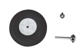
3 Caution: this model is not a toy! If you are a beginner to this type of powered model, please ask an experienced model flyer for help and support. If you attempt to operate the model without knowing what you are doing you could easily injure yourself or somebody else. Please keep your safety and well-being in mind at all times. Important: before you start construction Even if you have already built a large number of RC models please read right through these instructions and check all the kit components against the parts list. We have taken great trouble to keep construction as simple as possible, without making any compromises in the area of safety. Note regarding the film covering Minor creases or bubbles may develop in the film covering due to major fluctuations in weather conditions (temperature, humidity etc.); in rare cases you may even find a slight warp in a component. These minor faults are in the nature of film-covered built-up wooden structures, and can easily be corrected using a heat gun, as commonly used for modelling. Creases: Blow warm air over the area and rub down with a soft cloth. Wing warp: Hold the panel twisted gently in the opposite direction to the warp, and apply warm air to remove the creases from the covering. SAFETY PRECAUTION. + This is not a toy + Be sure that no other flyers are using your radio frequency. +The glow plug clip must be securely attached to the glow plug. + Do not flip the propeller with your fingers. + Keep loose clothing and wires away from the propeller. + Do not st art the motor if people are near. Do not stand in line with the side of the propeller. REPLACEMENT LARGE PARTS B A A. Cowlings. B. Wing panel. C. Fuselage. D. Horizontal stabilizer. E. Vertical stabilizer. F. Decal sheet. G. Aluminium wing dihedral brace. REPLACEMENT SMALL PARTS 1 2 D C G 5 E F Caution! do not heat the film more than is absolutely necessary. If the air or the iron is too hot, the film may melt and holes may be formed. This model is highly pre-fabricated and can be built in a very short time. However, the work which you have to carry out is important and must be done carefully. The model will only be strong and fly well if you complete your tasks competently - so please work slowly and accurately. When self-tapping screws have to be screwed into wood, apply a little white glue to prevent them shaking loose: just squirt white glue into the hole and fit the screw Fiberglass cover first fuselage. 2. Wheel (60mm). 3. Fiberglass cover first wing panel. 4. Spinner. 5. Retractable landing gear. 6. Tail gear. 6 3

 Install the")

 Install the metal")


4 INSTALLING THE AILERON - FLAP SERVO CONTROL HORN. INSTALLING THE AILERON - SERVO CONTROL HORN. 1) Install the rubber grommets and brass eyelets onto the aileron servo. 2) Install the metal connector onto servo arm. C/A glue. Flap Epoxy glue Bottom side of left wing Push C/A glue. Aileron C/A glue. C/A glue. Flap 4


5 3) Install the aileron servo as same as picture. C/A glue. Remove covering. Epoxy glue. C/A glue. Bottom of left. Repeat the procedure for the other wing half. 5


6 INSTALLINGCONTROL HORN OF THE AILERON Aileron Flap Bottom side. Micro control connector. - Using a ruler & pen to draw a straight line as below picture. Bottom side 4) Attach the micro control connector to the servo arms. Be sure to use the lock tie but it could free rotation. Straight line Remove covering 59mm Tracing a line with your finger and using a modeling knife remove a (3mm) wide strip on to the aileron control horn pre-cut slot-mounting. Aileron control horn slot C/A glue. Insert aileron control horn to the aileron. Pushrod wire aileron control horn. Flap control horn. 6


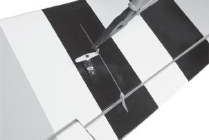
7 aileron control horn. Cut Aileron C/A glue. INSTALLING FLAP SERVO-CONTROL HORN. Remove covering Aileron control horn. Flap Bottom side Secure 7


8 Insert flap control horn as picture above. Flap control horn Secure Pushrod wire Flap control horn Cut 15mm Remove covering on pre-cut slot -mounting flap control horn. C/A glue 8


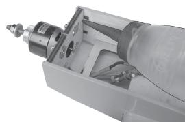
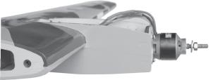
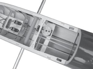
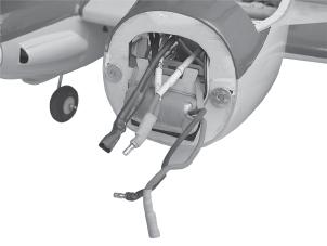
9 3x 15mm. Aileron Secure Flap Bottom side Repeat the procedure for the other wing half. INSTALLING ELECTRIC MOTOR. See pictures below: Epoxy glue Motor mount wood: 9
10 10

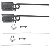
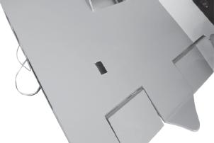
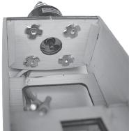
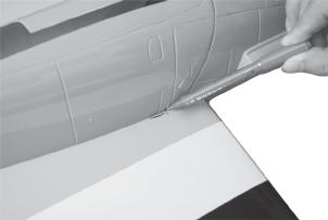
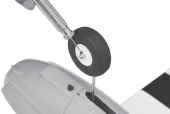
11 INSTALLING RETRACTABLE LANDING GEAR. Remove covering 11


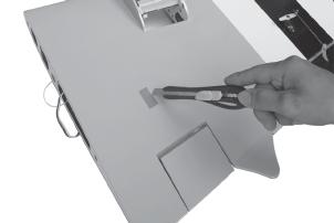
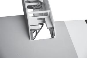
12 Cut out and reomver the balsa plywood as picture to place for the retract landing gear mounts. cut here Mark point Drill a hole 1.5 mm (diameter) 3 mmx 15mm Secure 12


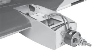
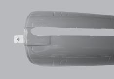
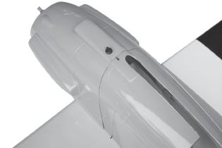
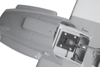
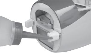
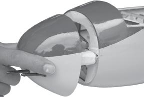
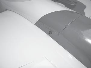
13 3 mmx 15mm ENGINE NACELLE-COWLING INTALLATION. Install the engine cowling as same as picture below. Bottom side Pushrod retract Cowling Bottom nacelle Remove covering through balsa wood on to pre-cut slot of bottom wing as picture below. Secure Mark point Bottom side Top side Secure 13


14 50mm Epoxy glue Center line 3 x 15mm Center line Secure Left side INSTALLING THE BOTTOM NACELLE 14


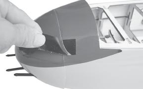
15 Pre-cut slot Pre-cut slot Pre-cut slot Cut C/A glue Bottom nacelle C/A glue 15


16 Left side Right side Mark line Mark line Left side Right side Mark line Mark line Right side Left side Right side 16


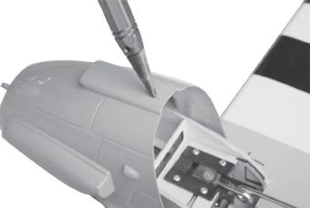
17 Push down & push on C/A glue 11mm Mark point Center line Mark point 17


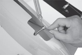
18 Drill a hole with 4mm diameter. Secure Secure 18


 Install the metal")
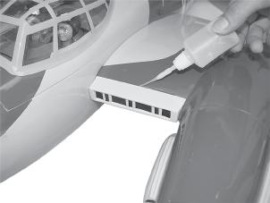
19 Top side Repeat the procedure for the other engine cowl. Another wing halft as same as process. INSTALLING THE SPINNER Install the spinner as same as picture below. 3 x 12mm. Top side Bottom side SERVO INSTALLATION. Secure 1) Install the rubber grommets and brass eyelets onto the elevator servo and nose gear servo. 2) Install the metal connector onto servo arm. Servo for retract only 19


 Mark the shape of the")

20 C/A glue HORIZONTAL STABILIZER INSTALLATION. 1) Using a modeling knife, cut away the covering from the fuselage for the stabilizer and remove it. C/A glue Remove covering 2) Draw a center line onto the horizontal stabilizer. Then put the horizontal into the fuselage. Top Center line. Top elevator. 3) Mark the shape of the vertical on the left and right sides onto the horizontal stabilizer using a left-tip pen. Bottom C/A glue Mark line 20


21 4) Remove the stabilizer. Using the lines you just drew as a guide, carefully remove the covering from between them using a modeling knife. When cutting through the covering to remove it, cut with only enough pressure to only cut through the covering it s self. Cutting into the balsa structure may weaken it. This could lead to possible failure during flight. Remove covering 5) When you are sure that everything is aligned correctly, mix up a generous amount of 30 minute epoxy. Apply a thin layer to the top and bottom of the stabilizer mounting area and to the stabilizer mounting platform sides in the fuselage. Slide the stabilizer in place and re-align. Double check all of your measurements one more time before the epoxy cures. Remove any excess epoxy using a paper towel and rubbing alcohol and hold the stabilizer in place with T-pins or masking tape. C/A glue Bottom 6. After the epoxy has fully cured, remove the masking t ape or T-pins used to hold the stabilizer in place and carefully inspect the glue joints. Use more epoxy to fill in any gaps that may exits that were not filled previously and clean up the excess using a paper towel and rubbing alcohol. Epoxy glue C/A glue ELEVATOR CONTROL HORN INSTALLATION. Installing elevator control horn as same as picture below. Elevator control horn. 21


22 ELEVATOR PUSHROD INSTALLATION. Elevator pushrod install as same as picture below. Remove covering on the precut-slot Elevator pushrod Elevator pushrod C/A glue Cut Elevator control horn Elevator control horn 22


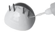
23 Secure Elevator pushrod Rudder pushrod MOUNTING THE TAIL WHEEL BRACKET. Bend and cut after 3 x 12mm Mark point Elevator servo 23


24 Secure the tail wheel bracket in place using three 3mm x 12mm wood screws. Be careful not to overtighten the screws. Remark RUDDER CONTROL HORN INSTALLATION. Rudder pushrod Rudder control horn Remove covering Secure 24


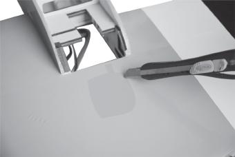
25 VERTICAL INSTALLATION. 1. Put the rudder in the fuse lage as same as picture below. Tail wheel wire 2. Mark the shape of the vertical on the left and right side of the rudder on to the horizontal stabilizer using a felt-tip pen. Mark point C/A glue 3. Now, remove the rudder and using a modeling knife, carefully cut just inside the marked lines and remove the film of the rudder. Just as you did with the horizontal stabilizer, make sure you only press hard enough to cut the film, not the balsa rudder. Also carefully remove the covering from the horizontal fin as below the lines which you drew as same picture below. 25


26 Remove covering Remove covering When cutting through the covering to remove it, cut with only enough pressure to only cut through the covering itself. Cutting into the balsa structure may weaken it. 4. Put the vertical stabilizer back in place. Using a triangle, check to ensure that the vertical stabilizer is aligned 90 degree to the horizontal stabilizer. Horizontal Stabilizer. 90º Vertical Stabilizer. Remove covering 5. When you are sure that everything is a aligned correctly, mix up a generous amount of 30 minute epoxy. Apply a thin layer to the slot in the mounting platform and to the vertical stabilizer mounting area. Set the stabilizer in place and re-align. Double check all of your measurements once more before the epoxy cures. Remove any excess epoxy using a paper towel and rubbing alcohol and hold the stabilizer in place with T- pins or masking tape. Allow the epoxy to fully cure before proceeding. Epoxy glue Remove covering Epoxy glue 26


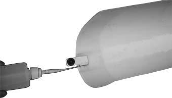
27 Epoxy glue 18 mm Bend 90 degree Cut C/A glue Mark point 21mm Epoxy glue Push C/A glue. Carefully make a 90 degree bend down at the mark point which was made. Cut off the excess wire, leaving about 18mm beyond the bend. 27


28 C/A glue Check to mark sure the wing and stabilizer are paralell. If they are not, lightly sand the opening in the fuselage for the stabilizer until the stabilizer is paralell to the wing. Elevator pushrod Elevator pushrod Gun Bend and cut after Fiber glass cover 28


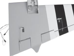
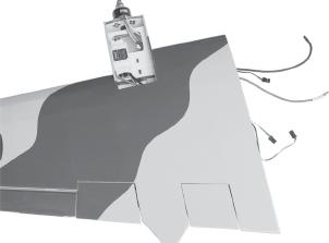
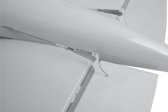
29 Apply epoxy and C/A glue Apply tape ATTACHMENT WING-FUSELAGE. See pictures below: RETRACT PUSHROD INSTALLATION Retract servo Apply epoxy Apply epoxy Metal conector (25mm) Push Servo arm 29


30 Secure Cut wing bolt secure Retract pushrod Retract pushrod look at in side - on the top size of fuselage. 30


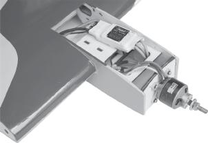
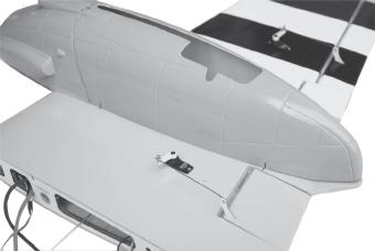
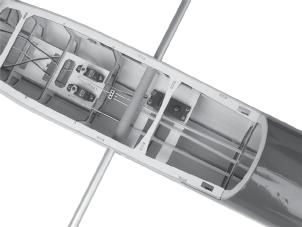
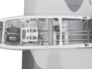
31 Retract pushrod look at - on the bottom size of wing. INSTALLING THE RECEIVER AND BATTERY. See picture below. Tie wrap. Tie wrap. Receiver Battery 31
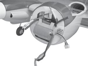
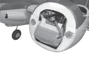
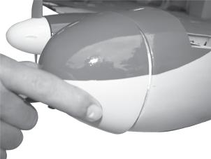
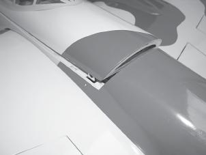
32 Secure Fiberglass cover first wing panel. C/A glue Installing the canopy as some as picture below. 32
 Mount the wing to the fuselage.")


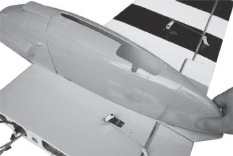
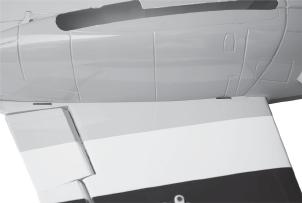
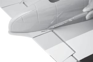
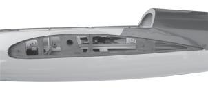
33 Fiberglass cover BALANCING. 1) It is critical that your airplane be balanced correctly. Improper balance will cause your plane to lose control and crash. THE CENTER OF GRA VITY IS LOCA TED 95MM BACK FROM THE LEADING EDGE OF THE WING. 2) Mount the wing to the fuselage. Using a couple of pieces of masking tape, place them on the top side of the wing 95mm back from the leading edge, at the fuselage sides. 3. Turn the airplane upside down. Place your fingers on the masking tape and carefully lift the plane. Accurately mark the balance point on the top of the wing on both sides of the fuselage. The balance point is located 95mm back from the leading edge. This is the balance point at which your model should balance for your first flights. Later, you may wish to experiment by shifting the balance up to 10mm forward or back to change the flying characteristics. Moving the balance forward may improve the smoothness and arrow- like tracking, but it may then require more speed for take off and make it more difficult to slow down for landing. Moving the balance aft makes the model more agile with a lighter and snappier feel. In any case, please start at the location we recommend. With the wing attached to the fuselage, all parts of the model installed ( ready to fly), and empty fuel tanks, hold the model at the marked bala first attempt to balance the model by changing the position of the receiver battery and receiver. If you are unable to obtain good balance by doing so, then it will be necessary to add weight to the nose or tail to achieve the proper balance point. 33
34 PRE-FLIGHT CHECK. CG 95mm 1) Completely charge your transmitter and receiver batteries before your first day of flying. 2) Check every bolt and every glue joint in your plane to ensure that everything is tight and well bonded. CONTROL THROWS. 1) We highly recommend setting up a plane using the control throws listed. 2) The control throws should be measured at the widest point of each control surface. 3) Check to be sure the control surfaces move in the correct directions. Ailerons : 10mm up 10mm down. Elevator : 10mm up 10mm down. Rudder : 15mm right 15mm left. 3) Double check the balance of the airplane. 4) Check the control surface. 5) Check the receiver antenna. It should be fully extended and not coiled up inside the fuselage. 6) Properly balance the propeller. We wish you many safe and enjoyable flights with your MOSQUITO MK VI
Instruction Manual book
 Instruction Manual book ITEM CODE BH53. SPECIFICATION Wingspan : 1,250mm 49.21 in. Length : 930mm 36.61in. Weight : 1.1kg 2.42 Lbs. Parts listing required (not included). Battery: 3 CELLS-LI-POLY-11.1V-2,500
INSTRUCTION MANUAL BOOK.
 INSTRUCTION MANUAL BOOK. SPECIFICATION Wingspan : 164 cm 64.57in. Length : 135 cm 53.15 in. Weight : 3.3kg 7.26 lbs. Servo : 7 servos. Radio : 4 channels. Engine : 61 cu.in-2 stroke. 91 cu.in-4 stroke.
PROCTOR. Instruction Manual Book 95% ALMOST READY TO FLY. Item code: BH154. SPECIFICATION ALL BALSA - PLY WOOD CONSTRUCTION. COVERED WITH ORACOVER
 Instruction Manual Book PROCTOR Item code: BH154. ALL BALSA - PLY WOOD CONSTRUCTION. COVERED WITH ORACOVER 95% ALMOST READY TO FLY SPECIFICATION Wingspan: 1,360 mm (53.54 in). Length: 1,480 mm(58.27 in).
Instruction Manual. Specification:
 Instruction Manual H I G Specification: Wingspan: 133 cm (52.3 inches) Length : 104 cm (40.9 inches) Weight : 1830gr Engine : 25-32 two stroke Radio : 4 channel - 4 servo H W I N G KIT CONTENTS: We have
HAWKER HURRICANE. Instruction Manual Book 95% ALMOST READY TO FLY. Item code: BH147. SPECIFICATION
 Instruction Manual Book Item code: BH147. HAWKER HURRICANE ALL BALSA - PLY WOOD CONSTRUCTION. COVERED IN A HEAT-SHRINK FILM WITH PRINTED. 95% ALMOST READY TO FLY SPECIFICATION Wingspan: 1,520 mm (59.84
NOORDUYN NORSEMAN. Instruction Manual Book 95% ALMOST READY TO FLY. Item code: BH157. SPECIFICATION
 Instruction Manual Book Item code: BH157. NOORDUYN NORSEMAN ALL BALSA - PLY WOOD CONSTRUCTION. COVERED WITH ORACOVER. 95% ALMOST READY TO FLY SPECIFICATION - Wingspan: 1840 mm (72.44 in). - Length: 1180
PERCIVAL P-56 PROVOST
 Instruction Manual Book. PERCIVAL P-56 PROVOST OLEO STRUTS LANDING GEAR. ALL BALSA - PLY WOOD CONSTRUCTION. COVERED WITH ORACOVER Glow and EP 95% ALMOST READY TO FLY SPECIFICATION: - Wingspan: 1,644mm
BUCKER BU 131 JUNGMANN ALL BALSA - PLY WOOD CONSTRUCTION. COVERED WITH ORACOVER
 Instruction Manual Book. BUCKER BU 131 JUNGMANN ALL BALSA - PLY WOOD CONSTRUCTION. COVERED WITH ORACOVER Glow and EP 95% ALMOST READY TO FLY SPECIFICATION: - Wingspan: 1,850 mm (72.83 in). Length: 1,660
Hand-made Almost Ready to Fly R/C Model Aircraft ASSEMBLY MANUAL
 Hand-made Almost Ready to Fly R/C Model Aircraft ASSEMBLY MANUAL Specifications Wingspan -----------------------.148 cm--------------- 58.3 in. Wing area ----------------------- 3474sq. cm ---- 538.4sq
INSTRUCTIONS FOR FINAL ASSEMBLY
 MS: 11 INSTRUCTIONS FOR FINAL ASSEMBLY Graphics and specfications may change without notice. Specifications: Wingspan -------------------------------------------- 156 cm, 61.42 in. Wing area ---------------------------------
FAIREY ALBACORE. Instruction Manual Book. Glow and EP. Item code: BH % ALMOST READY TO FLY SPECIFICATION:
 Instruction Manual Book. FAIREY ALBACORE ALL BALSA - PLY WOOD CONSTRUCTION. COVERED IN A HEAT-SHRINK FILM WITH PRINTED. Glow and EP 95% ALMOST READY TO FLY SPECIFICATION: - Wingspan: 1,693mm (66.65in).
MUSTANG P-51. Hand-made Almost Ready to Fly R/C Model Aircraft ASSEMBLY MANUAL
 MUSTANG P-51 Hand-made Almost Ready to Fly R/C Model Aircraft ASSEMBLY MANUAL Specifications Wingspan---------------------------------------- 60.5 in----------------------- 153.7cm. Wing area-------------------------------------
JUNKERS JU87- B2 STUKA
 Instruction Manual Book Item code: BH169. JUNKERS JU87- B2 STUKA OLEO STRUTS LANDING GEAR. ALL BALSA - PLY WOOD CONSTRUCTION. COVERED IN A HEAT-SHRINK FILM WITH PRINTED. 95% ALMOST READY TO FLY SPECIFICATION:
A S S E M B L Y M A N U A L
 A S S E M B L Y M A N U A L Kit features. Ready-made minimal assembly & finishing required. Ready-covered covering. Photo-illustrated step-by-step Assembly Manual. Specifications Wingspan --------------------------
INCLUDED IN THIS KIT: SPECIFICATION: NEEDED BUILDING TOOLS: REQUIRED EQUIPMENT:
 Please review this entire manual before beginning assembly. By doing so it will help you better understand each step as you progress in the actual building of your kit, and you will do a better job in
FUJI FA-200 AERO SUBARU
 FUJI FA-200 AERO SUBARU SEMI SCALE SPORT MODEL AERO SUBARU Assembly and Operations Manual Please review this manual throughly Before assembling or Operating The AERO SUBARU Semi scale sport model We ve
RYAN STA SAFETY PRECAUTIONS. "Sport Scale E-Power ARF" For Intermediate and Advanced Fliers. This radio control model is not a toy!
 RYAN STA "Sport Scale E-Power ARF" For Intermediate and Advanced Fliers. SAFETY PRECAUTIONS This radio control model is not a toy! First-time builders should seek advice from people with model building
Citabria Pro. Aerobatic Parkflyer. by Joel Dirnberger
 Citabria Pro Aerobatic Parkflyer by Joel Dirnberger Revision C: December 21, 2004 Citabria Pro Building Instructions Length: Wingspan: Wing Area: Flying Weight: Wing Loading: Functions: Specifications:
C-180 Builder s Manual
 C-180 Builder s Manual. May 20, 2002 Last revised July 11, 2002 Copyright! 2002 Douglas Binder, Mountain Models www.mountainmodels.com sales@mountainmodels.com (719) 630-3186 1 Required Equipment! Xacto
43in EPP Acrocub Instruction Manual
 43in EPP Acrocub Instruction Manual Specifications Wingspan: 43.3in (1100mm) Length: 41.3in (1050mm) Flying Weight: Approx. 1.5lb (670g) Dear Customer, Congratulations on your purchase of 43in EPP Acrocub
INCLUDED IN THIS KIT: SPECIFICATION: NEEDED BUILDING TOOLS: REQUIRED EQUIPMENT:
 Please review this entire manual before beginning assembly. By doing so it will help you better understand each step as you progress in the actual building of your kit, and you will do a better job in
Specifications. Before commencing assembly, please read these instructions thoroughly.
 INSTRUCTION MANUAL Before commencing assembly, please read these instructions thoroughly. Specifications Wing Span: 8.5 in / 30 mm Wing Area: 330 sq in /.3 sq dm Flying Weight: 6 oz / 70 g Fuselage Length:
uin RC FPRC ZERO Specificationss Empty Weight
 Flying Pengu uin RC FPRC ZERO Specificationss Wing Span 42.75 (1085 mm) Fuselage length 30.5 ( 775 mm) Empty Weight 9.5 10 oz. (150 160g) Estimated Flying Weight 20 255 oz. (320 400g) Wing Area: 151 sq.
DORNIER DO 27 SEMI SCALE SPORT MODEL DORNIER DO 27. Assembly and Operations Manual
 DORNIER DO 27 SEMI SCALE SPORT MODEL DORNIER DO 27 Assembly and Operations Manual Please review this manual throughly Before assembling or Operating The DORNIER DO 27 Semi scale sport model We ve used
LANDING GEAR. 1. Fit landing gear into slots on bottom of fuselage.
 LANDING GEAR 1. Fit landing gear into slots on bottom of fuselage. 4. Use channel-lock pliers to press blind nuts into position (note: drilled hole should be slightly smaller than shaft of blind nut for
DORNIER DO 27 SEMI SCALE SPORT MODEL DORNIER DO 27. Please review this manual throughly Before Assembling or Operating The DORNIER DO 27
 DORNIER DO 27 SEMI SCALE SPORT MODEL DORNIER DO 27 Assembly and Operations Manual Please review this manual throughly Before Assembling or Operating The DORNIER DO 27 Semi Scale Sport Model We ve used
(Build Instructions)
") (Build Instructions) Specifications * Wingspan: 58cm * Length: 50cm * Flying Weight: 59 grams * Channels: 3 (Rudder Elevator Throttle) * Suggested Receiver: 4Ch Micro * Motor: 8mm GearDrive * Prop: GWS
(Build Instructions) Specifications * Wingspan: 58cm * Length: 50cm * Flying Weight: 59 grams * Channels: 3 (Rudder Elevator Throttle) * Suggested Receiver: 4Ch Micro * Motor: 8mm GearDrive * Prop: GWS
Corvus Racer CC
 Corvus Racer 540 35CC Item No:L-G035008 Specifications Wing Span Length Wing Area Flying Weight Glow Gasoline Electric Radio mm mm 1200sq in (77.4sqdm) 9.9-12lbs(4.5-5.5kg) 91-1.20(2C) 1.10-1.40(4C) 20-40cc
FUSELAGE CONSTRUCTION
 FUSELAGE CONSTRUCTION Note: prior to building and gluing on the work surface use protective covering on your building surface. (wax paper or clear wrap) Fit the laser cut Fuselage Front and Fuselage Rear
ULS Cherokee. Ultra Low Speed aircraft for indoor RC flying. Zippkits. Specifications: Required to complete:
 Zippkits ULS Cherokee Ultra Low Speed aircraft for indoor RC flying. Specifications: Span- 28 inches Wing Area- 151 Sq/In Wing Loading- 3.0 ounces/ft Weight- 3.5 ounces RTF Build time- 1-2 Hours Radio-
HIGH-END TECHNOLOGY. Electric ducted fan Starfighter
 HIGH-END TECHNOLOGY RC Electric ducted fan Starfighter First we want to thank and congratulate you with your decision in buying one of our Kits. The Starfighter puts together very easily so there is not
MECOA EZ-4061 Trainer
 MECOA EZ-4061 Trainer EZ-4061 is a newly designed, Almost Ready to Fly kit. It is an extremely easy to control trainer with strong construction and excellent aerodynamic performance. This is a great choice
F3A -70E ASSEMBLY MANUAL
 F3A -70E ASSEMBLY MANUAL The new F3A-70E, was designed in an extremely lightweight structure, the all wood airframe, and the new revolutionary Lift Generator on landing gear give the F3A-70E an impressive
CARL GOLDBERG PRODUCTS, LTD.
 Eagle 400 WARNING A radio-controlled model is not a toy and is not intended for persons under 16 years old. Keep this kit out of the reach of younger children, as it contains parts that could be dangerous.
TWEETY 25 INSTRUCTION MANUAL. Almost Ready to Fly Nitro/Electric Aerobat FEATURES SPECIFICATIONS
 TWEETY 25 Almost Ready to Fly Nitro/Electric Aerobat INSTRUCTION MANUAL SPECIFICATIONS FEATURES WINGSPAN: 45.7 (1160mm) LENGTH: 38.6 (980mm) WING AREA: 370 sq in(24 sq dm) FLYING WEIGHT: Approx. 3.3 lbs
High performance 90mm fiberglass jet
 High performance 90mm fiberglass jet Assembly manual For intermediate and advanced fliers only! Specs Wingspan: 1255mm Fuselage length: 1250mm Flying weight: 2600-3000g Wing area: 22.6 dm² Wing loading:
SebArt professional line
 SebArt professional line Wind S 110 ARF ASSEMBLY MANUAL The new Wind S 110 ARF was designed by Italy aerobatic pilot, Sebastiano Silvestri. This professional ARTF kit is the result of Sebastiano s 20 years
Corvus Racer Colour schemes. AeroPlus RC Copyright 2013 All Rights Reserved
 Corvus Racer 540 59 Item No:A E050003 Specifications WING SPAN: 59"(1500mm) LENGTH: 54.1"(1374mm) WING AREA: 654sq.in.(42.2sq.dm.) FLYING WEIGHT: 4.6 5.3lbs(2000 2300g) Electric:Brushless outrunner 8Oz.
F-16 Falcon 70mm EDF
 F-16 Falcon 70mm EDF Instruction manual Specifications: Winspan: 640 mm Length: 990 mm Weight: 900-1100 gram Ducted fans 70mm x 1 Required tools and components:. 4 ch. Computer Radio system w/ 2 servos.
Super Sky Surfer 2000 Assembly Instructions
 Super Sky Surfer 2000 Assembly Instructions Note: Plug and Play version of the Sky Surfer comes with fuselage pre-glued and motor/servos installed. If you wish to route antennas or wires through the tail,
28in Super EVA Foam. F-22 Raptor Kit. Specifications. Wingspan: 27.5in (700mm) Length: 38.3in (975mm) Flying Weight: Approx. 1.
 Length: 38.3in (975mm) Flying Weight: Approx. 1.") 28in Super EVA Foam F-22 Raptor Kit Specifications Wingspan: 27.5in (700mm) Length: 38.3in (975mm) Flying Weight: Approx. 1.2lbs (530g) Dear Customer, Congratulations on your purchase of 28in F22 Raptor
28in Super EVA Foam F-22 Raptor Kit Specifications Wingspan: 27.5in (700mm) Length: 38.3in (975mm) Flying Weight: Approx. 1.2lbs (530g) Dear Customer, Congratulations on your purchase of 28in F22 Raptor
ASSEMBLY & OPERATIONS MANUAL
 TM TM AERO SUBARU 40-52 ARF ECS SEMI SCALE MODEL WITH POLYCOTE ECS ENHANCED GRAPHICS SYSTEM #VMA-S140B (blue as shown) #VMA-S140R (red) This model may be produced in a number of different graphic schemes
PITTS S2S CONSTRUCTION
 PITTS S2S CONSTRUCTION FUSELAGE CONSTRUCTION 1) Place the right fuselage side over the plan and mark the former positions. Place the left side over the right side and mark the former positions. Glue F1
ParkJet Builder s Manual
 ParkJet Builder s Manual Thank you for purchasing the ParkJet. The ParkJet is a profile ducted fan airplane that can be flown in a larger park. The ParkJet was initially designed by Scott Stoops and modified
25mm EPP SU31. Instruction Manual. Specifications
 25mm EPP SU31 Instruction Manual Specifications Wingspan: 39.4in (1000mm) Length: 42in (1070mm) Wing Area: 448sq in (28.9sq dm) Flying Weight: Approx. 1.5lb (650-710g) Dear Customer, www.valuehobby.com/su31-epp.html
Thank you for your purchase of the Lee Ulinger, FoamtanaS, Yak-55, or Extra 330 3D Depron foam, Aerobatic airplane.
 Thank you for your purchase of the Lee Ulinger, FoamtanaS, Yak-55, or Extra 330 3D Depron foam, Aerobatic airplane. Tools you will need to build Recommended additional items: #11 hobby knife Motor: Hacker
STEP 1 STEP 2 STEP 3. Page 2
 INSTRUCTION MANUAL Congratulations on your purchase of the Bullet ARTF - the first Almost Ready to Fly version of this classic lowwinger. Based on the original and timeless Bullet design, the new Ripmax
Sbach 1,2m 3D/aerobatic EPP model Building instructions
 Sbach 1,2m 3D/aerobatic EPP model Building instructions Please refer to the Diagram sheet Diagrams A, B Press 2 carbon strips (1x3x1000 mm) into the grooves in the sides of the fuselage central part (the
Edge 540 V3 35CC. Scheme A. Item No:L G Specifications. Flying Weight
 Edge 540 V3 35CC Item No:L G035016 Specifications Wing Span Length Wing Area Flying Weight Glow Gasoline Electric Radio Description 76 (1930mm) 74 (1879mm) 1200sq in(77.4sqdm) 9.9 12lbs(4.5 5.5kg) 91 1.20(2C)
Ryan STA Sport Scale Model Aircraft Assembly and Instruction Manual
 Ryan STA Sport Scale Model Aircraft Assembly and Instruction Manual Warning: This radio controlled model is not a toy. It requires skill to fly and is not recommended for the novice pilot. It should not
CARL GOLDBERG PRODUCTS, LTD.
 Chipmunk 400 WARNING A radio-controlled model is not a toy and is not intended for persons under 16 years old. Keep this kit out of the reach of younger children, as it contains parts that could be dangerous.
Parts Identification
 We are excited to introduce the Model Aero Aqua Sport. This is an excellent sport flyer, equally at home flying from grass fields, water, or even snow! The unique V-tail gives the Aqua Sport a distinctive
Instruction Manual. Item No: AL001
 Instruction Manual Item No: AL001 Specifications: Wingspan: 2037mm (80.2 in) Length: 1677mm (66 in) Wing Area: 65.5dm2 (1015.3 sq in) Flying Weight: 7.6kg (16.7 lbs) Engine(not incl.): 45-50cc Gas Radio(not
Switchback Sport Builder s Manual
 Switchback Sport Builder s Manual Thank you for purchasing the Switchback Sport. The Switchback Sport has been designed for the novice to intermediate pilot who wants a plane with good performance that
Assembly Manual / Airframe 65 Vyper SAFETY in Assembly SAFETY in Flying
 1 Assembly Manual / Airframe 65 Vyper Thank you for purchasing this 3DHobbyShop ARF RC aircraft. If you have any issues, questions, concerns or problems during assembly, please contact our tech department
Piper Cherokee /3 scale. Construction Manual
 Piper Cherokee 140 1/3 scale Construction Manual STAB CONSTRUCTION 1. Remove foam cores from cradle and place on flat surface. Inspect pieces before you epoxy halves together making sure leading and trailing
Specifications. Before commencing assembly, please read these instructions thoroughly. INSTRUCTION MANUAL
 INSTRUCTION MANUAL Before commencing assembly, please read these instructions thoroughly. Specifications Wing Span: 50 in / 170 mm Wing Area: 484 sq in / 31. sq dm Flying Weight: 3.5 lbs / 1600 g Fuselage
EXTRA 330SC 60CC. Item No:H G Specifications cc gas DA50,DA60, DLE55, DLE60(twin), 3W55. Description
, 3W55. Description") EXTRA 330SC 60CC Item No:H G060011 Specifications Wing Span Length Wing Area Flying Weight Gasoline Radio Description Carbon Fibre : 92" (2347mm) 84 1/2 " (2060mm) 1526.8 sq in(98.5sq dm) 16 17lbs(7300
EXTRA 330SC 60CC Item No:H G060011 Specifications Wing Span Length Wing Area Flying Weight Gasoline Radio Description Carbon Fibre : 92" (2347mm) 84 1/2 " (2060mm) 1526.8 sq in(98.5sq dm) 16 17lbs(7300
BOOMERANG TORUS. Aerobatic Sport Jet for 20 to 34 lbs (P80 to P160) thrust turbines.
 thrust turbines.") BOOMERANG TORUS Aerobatic Sport Jet for 20 to 3 lbs (P80 to P160) thrust turbines. Specifications: Span... 83" (2209mm.) Span with Wingtip Tanks 90" (2286mm.) Length...87" (2108mm.) Weight 29 Lbs.(13.15
BOOMERANG TORUS Aerobatic Sport Jet for 20 to 3 lbs (P80 to P160) thrust turbines. Specifications: Span... 83" (2209mm.) Span with Wingtip Tanks 90" (2286mm.) Length...87" (2108mm.) Weight 29 Lbs.(13.15
Aure. Radio required : 3 channels, 4 servos airplane radio. Specifications. * Specifications are subject to change without notice.
 A L M O S T- R E A D Y- T O - F LY Aure INSTRUCTION MANUAL Radio required : 3 channels, 4 servos airplane radio Specifications Wing Span Wing Area Flying Weight Fuselage Length 81.5 in / 2070mm 572.0 sq
HIGH-END TECHNOLOGY. Electric ducted fan rafale
 HIGH-END TECHNOLOGY RC Electric ducted fan rafale First we want to thank and congratulate you with your decision in buying one of our Kits. The Rafale puts together very easily so there is not much explanation
T-15 EDF INSTRUCTION MANUAL. Wingspan.31in. Weight..2.5 lb. EDF...70mm 12 Blade ToughJets, LLC Kittery, ME Page 1 of 22.
 TM T-15 EDF INSTRUCTION MANUAL Specifications Wingspan.31in Length..41.75in Wing Area 515 sq in EDF...70mm 12 Blade Weight..2.5 lb Radio...3 channel Motor...Brushless Battery 14.8v 2200mah 40c 2013 ToughJets,
94 Yak 54 ARF WARNING
 94 Yak 54 ARF WARNING A radio-controlled model is not a toy and is not intended for persons under 16 years old. Keep this kit out of the reach of younger children, as it contains parts that could be dangerous.
INSTRUCTION MANUAL. Specifications. Wing Area Flying Weight Fuselage Length. 28 oz / 800 g 30.0 in / 760 mm
 ALMOST-READY-TO-FLY INSTRUCTION MANUAL Requires : -channel radio w/ micro servos, Outrunner Motor w/ Propeller Adaptor 0A Brushless ESC, 3 cells 11.1V 100 mah Li - Po battery & charger. Wing Span Wing
Stream NXT - assembly instructions
 Stream NXT - assembly instructions Recommended settings CG (measured from root leading edge): Speed/launch camber (+down, near the wing root): Cruise camber (+down, near the wing root): Thermal camber
Specifications Wingspan: 43cm Flying Weight: 33 grams (with battery) Channels: 3 Suggested Receiver: 4Ch Micro Motor: 7mm Brushed Geardrive
 Channels: 3 Suggested Receiver: 4Ch Micro Motor: 7mm Brushed Geardrive") Specifications Wingspan: 43cm Flying Weight: 33 grams (with battery) Channels: 3 Suggested Receiver: 4Ch Micro Motor: 7mm Brushed Geardrive Airframe Kit (Included Contents) * Airframe Parts Sheets (Depron)
Specifications Wingspan: 43cm Flying Weight: 33 grams (with battery) Channels: 3 Suggested Receiver: 4Ch Micro Motor: 7mm Brushed Geardrive Airframe Kit (Included Contents) * Airframe Parts Sheets (Depron)
Your kit contains the following parts. Please check your kit for any missing or damaged parts before starting construction.
 Your kit contains the following parts Please check your kit for any missing or damaged parts before starting construction COMPLETE KIT PARTS LIST 1 Plan Sheet #1 1 Plan Sheet #2 2 Decal Sheet 2 White Tissue
Zlin Z-526 AFS INSTRUCTION MANUAL SAFETY PRECAUTIONS. Specification:
 Zlin Z-5 AFS Specification: Length Wing Span Wing Area :75 mm(7.") :05 mm(") :7.sq.dm.9sq.ft Wing Loading :70.9g/sq.dm.oz/sq.ft Flying Weight :5.kg(.9lbs) Radio :ch & servos Engine: :cc-cc INSTRUCTION
Building Instructions. Scarlet RC model aircraft. Order No. 1308/00. Specification: approx mm. rudder, flaps, throttle.
 Building Instructions RC model aircraft Order No. 1308/00 Specification: Wingspan Length Wing area All-up weight Wing loading RC functions approx. 3000 mm approx. 1270 mm approx. 53.5 dm² approx. 1.45
105" TIGER MOTH ARF INSTRUCTION MANUAL VERSION 1.0
 105" TIGER MOTH ARF INSTRUCTION MANUAL VERSION 1.0 Step 1. Installation of the aileron servos 1) Mount aileron servo to servo mounting blocks with servo s screws. Install servo mounting plate with screws.
S.E.5a (Build Instructions)
") S.E.5a (Build Instructions) Specifications Wingspan: 38 cm Length: 31cm Flying Weight: 41 Channels: 3 (Rudder Elevator Throttle) Suggested Receiver: 3Ch Brick Motor: 7mm Geared Motor Airframe Only Kit
S.E.5a (Build Instructions) Specifications Wingspan: 38 cm Length: 31cm Flying Weight: 41 Channels: 3 (Rudder Elevator Throttle) Suggested Receiver: 3Ch Brick Motor: 7mm Geared Motor Airframe Only Kit
TIGER SHARK-40 ARF ASSEMBLY MANUAL
 TIGER SHARK-40 ARF ASSEMBLY MANUAL Kangke Industrial USA, Inc. 65 East Jefryn Blvd. Deer Park NY 11729 http://www.kangkeusa.com E-mail: info@kangkeusa.com Tel: 1-877-203-2377 Fax: 1-631-274-3296 Congratulations!
Skymaster ARF F-18E Instructions Manual
 Skymaster ARF F-18E Instructions Manual first: Take out the front servos mount, install front fuel tank before installing nose cone connect nose cone to fuselage by 6 screw Take out the 6 screws and Bottom
RESolution V2 Manual
 RESolution V2 Manual Note for the German Manual: Yellow Bottle thick CA Pink Bottle Med CA Blue tube 5 minute Epoxy Green tube 90 Minute Epoxy Construction of the Fuselage Step 1: Cover the plan with a
90 WING SPAN P-51D MUSTANG (COPYRIGHT PROTECTED 2014) ALL RIGHTS RESERVED
 ALL RIGHTS RESERVED") 90 WING SPAN P-51D MUSTANG (COPYRIGHT PROTECTED 2014) ALL RIGHTS RESERVED GENERAL INSTRUCTIONS This design is basically an enlargement of the very popular fun scale Mustang 60 Size. You can build it light
90 WING SPAN P-51D MUSTANG (COPYRIGHT PROTECTED 2014) ALL RIGHTS RESERVED GENERAL INSTRUCTIONS This design is basically an enlargement of the very popular fun scale Mustang 60 Size. You can build it light
This pictorial document contains assembly recommendations including some fit and finish details that will be helpful when building this airplane
 This pictorial document contains assembly recommendations including some fit and finish details that will be helpful when building this airplane Problems found with this kit and a flight performance review
SNIPE 2 Recommendations for assembly
 Accessory kit: 1. The list of parts and materials to build: Parts set: 1 - Launching peg; 2 - Aileron clevises (with M2.5 thread); 3 - Stabilizer control horn; 4 - Rudder control horn; 5 - Set of screws
Taylorcraft Indoor / Cul-De-Sac Flyer
 Taylorcraft Indoor / Cul-De-Sac Flyer Taylocraft Specifications Wingspan: 28.0 in. Wing Area: 117 sq. in. Weight (Ready to Fly): 3.0 3.1 oz. Wing Loading: 3.7 3.8 oz. / sq. ft. LIABILITY RELEASE In that
AT channel 6 servos
 Wing Span: Wing Area: Fuselage Length: Flying weight: Power system: Radio: 60.7in/1540mm 561 sq in/36.3 sq dm 44.1in/1120mm 6.9 Ibs/ 3100g 46(2C0/71(4C) 5 channel 6 servos AT6-46 INSTALLING AILERONS Begin
RADIO CONTROL MODEL / RC FLUGMODELL INSTRUCTION MANUAL
 RADIO CONTROL MODEL / RC FLUGMODELL INSTRUCTION MANUAL SPECIFITIONS Wingspan...57.5 in. / 146cm Length...50 in. / 127cm Engine...46 2T /.70 4T or Electric equivalent. Radio...4 ~ 6 channel Almost ready
30% Edge 540T Almost Ready to Fly
 Lanier R/C 30% Edge 540T Almost Ready to Fly WARNING! THIS IS NOT A TOY! THIS IS NOT A BEGINNERS AIRPLANE This R/C kit and the model you will build from it is not a toy! It is capable of serious bodily
35 Magnum. Instruction Manual
 EPP EPP 35 35 Magnum Rebel Z Instruction Manual This is how your kit will arrive When cutting the hardware package open use caution. The contents are semi-coiled to fit in the box. They will spring open
E-AERO EPP PITTS KIT From BP HOBBIES. Parts Included in kit
 E-AERO EPP PITTS KIT From BP HOBBIES Parts Included in kit Thank you for purchasing the BP Hobbies/E-aero EPP Pitts. Please take the time to read through the instruction manual before beginning the build.
1/6 PA-25 PAWNEE. *Specifications are subject to change without notice.*
 1/6 PA-25 PAWNEE INSTRUCTION MANUAL [ A335 Kit ] Wing Span : 72 in / 1830 mm Wing Area : 736 sq in / 47.5 sq dm Flying Weight : 6.6 lbs / 3000 g Fuselage Length : 48 in / 1220 mm Requires : "Glow Power"
Cheeper Assembly instruction
 1. Equipment, materials and tools for assembly.......2 2. Assembly.....3 3. Setting of the model.....11 1. Equipment, materials and tools for assembly 1 Wing; 2 Fuselage; 3 Stabilizer; 4 Fin; 5 Dowel for
Spitfire Mk.IX ARF. Electric retract system. TopRCModel-USA.com
 Electric retract system Thank you very much for purchasing our TRCM optional electric retract set, all our products were passed strict QC before they shipped out to the customers. In order to avoid probably
FOKKER D.VII 1:7.4. No.EP-46K. MTH HOBBY PRODUCTS INDUSTRIAL CO., LTD. MTH HOBBY 2015
 No.EP-46K FOKKER D.VII 1:7.4 MTH HOBBY PRODUCTS INDUSTRIAL CO., LTD. www.mth.com.tw mthhobby@mth.com.tw MTH HOBBY 2015 SPECIFICATION: Wing span: 1200mm Wing area: 41 dm Length: 990mm Weight: 1400g, including
Magpie. Foam Trainer. Magpie Specifications
 Magpie Foam Trainer Magpie Specifications Length: 34in. Wingspan (SF): 46in. Wing Area (SF): 414in 2 Wingspan (SP): 40in. Wing Area (SP): 360in 2 Weight (without battery): 12oz. Thank you for purchasing
MXS R 30CC. Item No:L G Specifications. 67 1/2"(1720mm) (2C) (4C) 26 35cc gas DLE 30/35RA MLD35 JC30Evo.
 (2C) (4C) 26 35cc gas DLE 30/35RA MLD35 JC30Evo.") MXS R 30CC Item No:L G030008 Specifications Wing Span Length Wing Area Flying Weight Glow Gasoline Electric Radio Description Covering Material Carbon Fibre : 75"(1915mm) 67 1/2"(1720mm) 1023sq in(66sq
MXS R 30CC Item No:L G030008 Specifications Wing Span Length Wing Area Flying Weight Glow Gasoline Electric Radio Description Covering Material Carbon Fibre : 75"(1915mm) 67 1/2"(1720mm) 1023sq in(66sq
Dandy Sport Builder s Manual
 Dandy Sport Builder s Manual Thank you for purchasing the Dandy Sport. The Dandy Sport has been designed as an easy to build aileron trainer. Take your time and enjoy building this plane. Specifications:
Hot Stik ARF WARNING. Copyright 2005 Carl Goldberg Products LTD CARL GOLDBERG PRODUCTS, LTD.
 Hot Stik ARF INSTRUCTIONS WARNING A radio-controlled model is not a toy and is not intended for persons under 16 years old. Keep this kit out of the reach of younger children, as it contains parts that
Cover the wing trailing edge and the aileron leading edge with strapping tape as shown.
 Cover the wing trailing edge and the aileron leading edge with strapping tape as shown. The aileron hinges are done using strapping tape on the top and bottom surfaces of the ailerons as shown. Make sure
JTM 90mm EDF Viper Jet Installation Manual
 JTM 90mm EDF Viper Jet Installation Manual Provided by ERJets www.erjets.com 1 Disclaimer: Welcome onboard! This radio controlled jet is not a toy. It has the capability of flying in high speed and therefore
FLITZEBOGEN-2 Assembly instructions
 FLITZEBOGEN-2 Assembly instructions Trim the end of the fuselage to the length of 925mm from the nose. Be careful to avoid splitting the carbon fibers. Sand the base of the stab mount in preparation for
Extra 330LT CC. 2 Colour schemes H-G120001A ORACOVER FERRARI RED # ORACOVER WITH # ORACOVER BLACK # ORACOVER SILVER #
 Extra 330LT 85-125CC Item No:A-G120001 Specs: WING SPAN: LENGTH: WING AREA: FLYING WEIGHT: ENGINE: RADIO: Description Covering Material Carbon Fibre: 111 (2833mm) 100" (2530mm) 2139sq in (138sq dm) 25.3-28lbs
SwitchBack Senior. SwitchBack Senior Specifications
 SwitchBack Senior SwitchBack Senior Specifications Wingspan: 55.4 in. Length: 41 in. Wing Area: 597 sq. in. Weight (Ready to Fly): 34 to 37 oz. Wing Loading: 8.2 to 8.9 oz. / sq. ft. Version 1.05, March
L 410 UVP-E Turbolet. Recommended equipment and guide for the building of RC model aircraft.
 L 410 UVP-E Turbolet Recommended equipment and guide for the building of RC model aircraft. - 1 - History of L-410 It has been 45 years since the first small commercial L-410 prototype took off. The first
87 Extra 330 ARF WARNING
 87 Extra 330 ARF WARNING A radio-controlled model is not a toy and is not intended for persons under 16 years old. Keep this kit out of the reach of younger children, as it contains parts that could be
LANIER - Double Trouble - INSTRUCTIONS. Tail 1 T1 ¼ Balsa 1 T2 ¼ Balsa 2 T3 ¼ Balsa 1 T4 ¼ Balsa 1 T5 ¼ Balsa 1 T6 ¼ Balsa 2 J1 ¼ Balsa 2 J2 Lite ply
 Tail 1 T1 ¼ Balsa 1 T2 ¼ Balsa 2 T3 ¼ Balsa 1 T4 ¼ Balsa 1 T5 ¼ Balsa 1 T6 ¼ Balsa 2 J1 ¼ Balsa 2 J2 Lite ply Other Parts 2 Aluminum Gear 1 3/32 Music wire tail skid 2 Elevator and J-plane joiner wire
Revolution 3D-mini ARF
 Revolution 3D-mini ARF 1 Included Hardware 4 Dubro Micro Control Horns #DUB848 2.32 x 18" Linkage Wire (Music Wire) 1 1.5 x 1.25 x 1/8 Balsa Ply (for motor mount) 1 5" piece of Velcro (Optional recommended,