S.E.5a (Build Instructions)
|
|
|
- Cecily Pope
- 5 years ago
- Views:
Transcription
 Suggested Receiver: 3Ch Brick Motor: 7mm Geared Motor")
 * Carbon pushrods * Wheels and rubber tyre rings * Fine sand paper * Control")
 Needed to")


1 S.E.5a (Build Instructions) Specifications Wingspan: 38 cm Length: 31cm Flying Weight: 41 Channels: 3 (Rudder Elevator Throttle) Suggested Receiver: 3Ch Brick Motor: 7mm Geared Motor Airframe Only Kit (Included Contents) * Airframe Covering Parts (balsa) * Airframe Skeleton (hardwood) * Carbon pushrods * Wheels and rubber tyre rings * Fine sand paper * Control linkages Complete Kit (Also contains these items) * Receiver (brick style 3ch) * Motor 7mm Dual Geared * 140mm Propeller * Motor and receiver pre-wired (no soldering) Needed to Complete * Thick CA Glue * Micro Phillips Head Screwdriver * Hobby Knife * Ruler * Household Pins * Hobby Masking or Other Tape * Receiver Transmitter Charger Battery * Tweezers * Patience * Keen Eyesight * Steady Hands Battery Options The Nanotech 300mah 1S battery is recommended for best balance. If using the Nanotech 130mah or similar battery, you will also need to add some ballast to the nose.


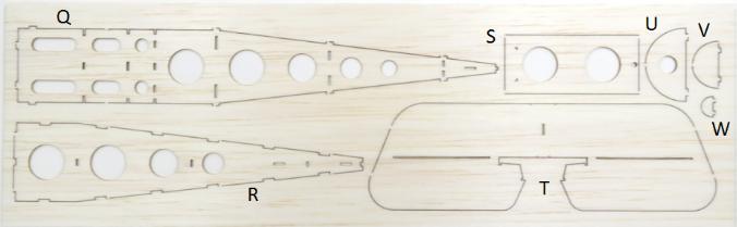
2 Before You Start This airframe has been designed to fit together easily with all components precision drilled and CNC cut from high quality balsa and paulownia wood. However, you will be working with very small components, so you will need patience and keen eyesight. We recommend working in a very well lit area and taking a break between stages to rest the eyes and hands. Most of all, take your time, enjoy the building experience and you will be proud of what you have produced in the end. First, refer to this and the following page to ensure that you have all the required airframe components in your kit.

3


 you may need to widen the gaps and give the tabs a bit of a trim to allow them to slip")

4 Step 01 Removing the Parts Assemble these parts for the first stage of the fuselage. When removing the parts from the sheets take your time and use a hobby knife instead of pressing them out with your fingers. Refer to the images below and glue the various parts in place. Make sure that after gluing the parts on top, you turn it over and clear out the glue from any slots which the bottom parts fit into. Glue the bulkheads in place first and then the side rails. For the side rails (part I) you may need to widen the gaps and give the tabs a bit of a trim to allow them to slip in easily. The small part (b) can be glued in place last. Insert it at an angle from the back to slide it in and then straighten it up to engage the tabs on the side rails. Ensure that when you glue in place the front motor mount section that the motor mount cutout section points to the right not the left. This gives a little right thrust on the motor.


5 The completed top section Pointing slightly to right Part r is the door hatch. Glue the magnet in place. Step 02 The Fuselage Frame


6 Use a ruler to press down on the body and bend each side piece at this point slightly Glue both sides in place but don t continue over the top yet. Glue in place the bottom surface and the two side pieces (part H) which go either side of the bottom hatch.


7 Step 03 Fuselage Covering Glue the parts below in place starting with part N the thinner one. Then glue part M in place. Finally glue part 5 in place. Be careful that the glue on the rear of part M doesn t block the two rectangular holes in the body former where the bottom hatch cover needs to fit. For the hatch cover before you glue the magnet in place check how it attracts to the other magnet in the fuselage so you don t glue the magnet in the wrong way. Finally, you may need to trim or sand the hatch cover and the holes in the fuselage where the locating tabs fit to allow it to fit more easily. Also use some scrap balsa to strengthen in by gluing on cross supports against the grain (the gap in the middle is required to clear the spar in the fuselage)


8 Step 04 Base Plate and Engine Cowl With your finger, dab some water on both sides of the fuselage frame and also on the top cover sheet (part 1). Allow the water to soak in and the balsa will be come easily bendable, The top edges of the fuselage sides will need to be trimmed until the meet flush and sit down on the fuselage formers. Use hobby masking tape to bend the sides over in place and set somewhere to allow the wood to dry (not in the sun). At this stage the pieces have not been glued just allowing to dry in the correct shape. They will be glued in place later after they dry. Step 05 Fitting the Base Plate For the tail section also give it a slight bend and let it dry. You can tape it in place on the airframe to dry It will also need to be trimmed later once the airframe sides are glued in place. Once the fuselage sides are dry glue them in place and secure with hobby tape while drying. The top section can now be glued in place. But first, it must be trimmed around the cockpit area and also down the sides. Either trim ½ millimeter at a time or sand it back so that it fits in place and sits down against the body formers. Once the fit is correct, glue it in place and tape to hold it with modeling masking tape. Step 06 Fuselage Top Cover


9 Step 07 Stabilizer Brace Glue part 3 in place but when you do, only glue it at the front. Do not glue it on the bottom to the fuselage sides. Later, the fuselage sides will be cut where the dotted line is and the slice removed to make way for the tailplane to slide in. For this reason we do not want this part glued on the bottom. After it has dried well sand the part down carefully so it matches the fuselage shape. Assemble the parts listed below to build the engine cowl. Build the frame first noting that the thinner U shaped piece (Part P) is glued in place first and the thicker similar shaped piece then goes on the front of that.


.")
10 Wet the piece of balsa to be bent around the frame on both sides and slowly work it into a curved shape. Then without gluing, tape it to the frame and let it dry to this shape. After the piece is fully dry it can be glued in place. Note: This part is needed to keep the cowl straight and aligned while gluing on the covering. But it will be cut away once the cowl has fully dried. The latches on the bottom can then also be glued in place. You may need to sand or file the gaps to allow them to slide in easily. Endure that they slide all the way in to be flush as shown in the image on the right. You may need to sand or trim the hinges and the slots they fit into if they don t exactly line up or it is hard to press the cowl into place. Glue the battery plate in place (Part C). Now gently cut away the section at the back as shown. Note: Rear spar has been cut away once the cowl assembly is fully dry. This is required to allow it so slide in place when the battery is fitted. Your fuselage should now look like this. Give it a light sand to smooth off any joins.

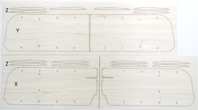
11 Apply the waterslide transfers as shown in the image on the left. Lay out your parts the same as in the picture (look at the wing tips and match the longer edge and shorter edge). Note that the shorter wings on the top of the image near the fuselage are actually the top wings (there is a middle section missing which actually makes them longer than the bottom ones once fitted to the plane). So the stickers on the top wing (nearest the fuselage) are on the top of the wings. The stickers on the bottom wing are on the underside. First cut the water slide stickers out from the sheet. Cut exactly around the edges of the shapes. Soak them in a bowl of water till they slide on the paper easily and slide them directly off the paper onto the surfaces. Dab them with a tissue to remove excess water don t wipe them. Allow to fully dry before continuing. Note: The vertical stabilizer is not glued in yet just attached in this image for demonstration. Ribs - Glue in the wing ribs in the positions shown above. The top wing has been flipped over in this image. Note that on the shorter wing (top wing), the second slots in from the tips are actually for the struts, not the ribs. On the bottom wings the slots for the struts actually line up with one of the ribs. After gluing in this rib, turn the wing over and make sure that you clear any glue from the strut anchor slots. After they have dried you may like to lightly sand around the edges of the wings and round off the edge on the top side. Step 08 Wing Braces To mount the wing braces you must cut away the pre cut sections in the fuselage as shown in the image on the top left. You don t need to cut at the ends of the pre-cut lines. Just cut a small section out in the middle and then see how much you need to cut out to allow the braces to fit in neatly. These can be glued in or screwed in with the screws provided. We suggest screwing them in for easy removal if needed later.


12 Glue in place the cross brace and the middle section (Part G) Step 09 Attaching The Wings The next task is to glue on the wings and wing struts. Follow the images below to attach the top and bottom wings. When gluing the wings in place, tape them with modeling masking tape as shown in the above video to align the two surfaces. Continue with the lower wings and wing struts, and allow them to dry completely before continuing.


 Don t glue in place the control horns till you verify which sides your receivers elevator and rudder pushrods will go")
13 Step 10 Hinging The Control Surfaces Glue in place part i into the tail plane. As this part is important for the strength of the elevators, it s a good idea to smear a thin layer of glue on both sides where it joins to the balsa. Glue on the hinge strips as shown here keeping them clear of the balsa tabs which join the moving surfaces to the tailplane surfaces. These tabs will be cut out later to allow the surfaces to move. Also cut along the dotted line to make the horizontal stabilizer slot. Sand either side as needed so the horizontal stabilizer sits level. Cut a slot slightly to one side here to allow the bottom hinge from the fin to slot into. (check which side you actually glued the hinge on the vertical stabilizer first) Don t glue in place the control horns till you verify which sides your receivers elevator and rudder pushrods will go on. It s a good idea to set up your radio gear and lay it next to the plane and actually move the rudder and elevator sticks to confirm which side the control horn needs to be on for each. Also, note that you should do this with the plane resting upside down on the bench as the receiver board will be mounted upside down in the bottom of the plane.


14 If you have purchased the complete kit version of this plane, the Receiver 24R6CLV11 DSM2 Compatible Linear 5Ch Brick receiver board will be included. To use this receiver you will need to reverse the direction of the rudder and elevator servos by adjusting settings on your transmitter. Glue the control horns in place as shown here. Note: the control horn with the longer base is for the rudder and the one with a shorter base is for the elevator. Step 11 The Undercarriage Attach the undercarriage as shown below. You may have to trim or sand the gaps in the joint to ensure that the strut inserts all the way in to the position indicated on the image on the left. To make the wheels, there are three discs to each one. The slightly smaller disc goes in between the two others to make a small groove in the middle which the o-ring sits in. Glue these together with the plastic part inserted to keep them aligned. Allow to dry fully before using a small amount of glue to attach the o-rings. Work slowly and gently when attaching the o-rings. Cut some 2mm lengths of the heat shrink tube and use these on the inside of the wheel as


15 spacers. The outer one can have some glue added to keep it in place. Also glue the carbon axel to the balsa strip. Construct the gun and wind shield as shown here. It is better to glue the gun to the top wing and then glue the gun base to the fuselage so they are touching. Make sure that a minimal amount of carbon rod is protruding from the back of the gun mount. This will allow room for the windshield to be mounted. The exhausts are made from the following pieces. Construct them as shown below.


. Two 1mm pieces of offcuts glued in place.")


16 Colour them black with a felt pen and glue them on to the engine cowl in the position marked. Mount the motor as shown here. You will need to add some down thrust by placing 2 pieces of wood under the rear edge of the motor mount. Use a 1mm thick pieces of hardwood offcut from the parts template sheets. Cut it to be 9mm long and 3mm wide and glue in place as shown below before mounting the motor (attach propeller before mounting motor). Two 1mm pieces of offcuts glued in place. This amount of down-thrust is required Don t press the propeller all the way on the shaft. Leave about 5mm gap between the rear of the prop and the gear face. You will need to sand down the thick block on the front of the plane on the bottom edge to make more clearance for the prop. See this tutorial on how to safely attach a prop to a geardrive shaft without bending the shaft. Also attach the Velcro dot as shown in the image on the right above to hold the battery in place.
 diagram at the bottom of this document and test the position of your gear to make sure it will balance at the correct point.")


17 In the next section we will be mounting the receiver. First, refer to the COG (balance point) diagram at the bottom of this document and test the position of your gear to make sure it will balance at the correct point. Mount ther receiver as far forward as possible using the strip of velcro or even better by gluing it in place. The image below shows the correct position. This is a slow and delicate job so take your time. A pair of tweesers will make the job much easier. Attach only this control linkage to the ends of the two control rods. Use a dab of glue to tack them in place and cut a short length of heat shrink from the tube to cover them with. Heat the heat shrink with a soldering iron or something else hot. Then insert these and connect them to the receiver as shown above. Leave the control surface parts as they are for now. The next thing you need to do is set up your transmitter. Turn it on and connect the battery to the receiver and check it is all working correctly. Look at which way the pushrods are moving and reverse the servo direction on the transmitter settings if needed.


18 Most importantly, before you attach the control surfaces check that you have the settings such as trims set to zero on the trasnsmitter. Finally use some heat source such as a soldering iron to shrink the heat shrink on the control surface linkages.. DO NOT use the transmitter to move the control surfaces yet! Step 12 Control Surfaces You must first cut away the tabs on the elevator and rudder surfaces to allow tyhem to move.


19 The correct point for the centre of balance is shown below. Ensure your plane is balanced at this point. This is a scale aircraft and as in the design of the actual aircraft, the nose is very short. In the actual aircraft, a very heavy motor sat up the front. However, in a model, the motor tends to be much lighter comparatively. You may therefore need to add some additional ballast to the nose of the plane to make it balance at the desired point. Centre of balance 29mm from the leading edge of the top wing. Control Surface Deflection Use the images below as a guide to how much maximum deflection you will need on the control surfaces. Do not exceed this amount of throw on the rudder as it will cause plane to roll to an excessive amount. You will most likely need to dial down your throws on your transmitter to around 50 to 60 percent. We also suggest that you set the differential to about 35% if your transmitter supports this function. We recommend using a 300mah battery to add the needed ballast to the front of the plane. If you have purchased the Complete Kit version, the adapter below will be included in the kit. A 130mah battery will also be adequate to power this aircraft. However, if you are using this size battery you will need to add more ballast to the front of the plane.


20 Note: Alternate setup. Instead of a receiver brick, you may choose to use a micro receiver with a brushed speed controller and servos. The dotted square in the receiver mounting board can be cut out and servos mounted instead. The recommended parts for this type of setup are shown below. Alternate Setup Parts List. Gearbox 7mm Base Mount Prop 140 mm Plastic ESC Brushed Micro 1S 3A Servo 5320 Black DT Rx34d Receiver Unit (Another receiver option) Receiver 4Ch R415 DSMX DSM2 Compatible


21 A sample flight video A little windy for this bird, but still able to be flown outside. Further Optional Modifications This model can also be converted to use a conventional receiver with micro servos instead of the standard brick type receiver with linear servos. It can also be modified to have ailerons on the lower wing. Please see the page below on our website for instructions. Copyright MicronWings 2016: All rights reserved. This manual is for personal use only. No unauthorized copying or digital distributing permitted without permission from MicronWings.
(Build Instructions)
") (Build Instructions) Specifications * Wingspan: 58cm * Length: 50cm * Flying Weight: 59 grams * Channels: 3 (Rudder Elevator Throttle) * Suggested Receiver: 4Ch Micro * Motor: 8mm GearDrive * Prop: GWS
(Build Instructions) Specifications * Wingspan: 58cm * Length: 50cm * Flying Weight: 59 grams * Channels: 3 (Rudder Elevator Throttle) * Suggested Receiver: 4Ch Micro * Motor: 8mm GearDrive * Prop: GWS
Specifications Wingspan: 43cm Flying Weight: 33 grams (with battery) Channels: 3 Suggested Receiver: 4Ch Micro Motor: 7mm Brushed Geardrive
 Channels: 3 Suggested Receiver: 4Ch Micro Motor: 7mm Brushed Geardrive") Specifications Wingspan: 43cm Flying Weight: 33 grams (with battery) Channels: 3 Suggested Receiver: 4Ch Micro Motor: 7mm Brushed Geardrive Airframe Kit (Included Contents) * Airframe Parts Sheets (Depron)
Specifications Wingspan: 43cm Flying Weight: 33 grams (with battery) Channels: 3 Suggested Receiver: 4Ch Micro Motor: 7mm Brushed Geardrive Airframe Kit (Included Contents) * Airframe Parts Sheets (Depron)
Citabria Pro. Aerobatic Parkflyer. by Joel Dirnberger
 Citabria Pro Aerobatic Parkflyer by Joel Dirnberger Revision C: December 21, 2004 Citabria Pro Building Instructions Length: Wingspan: Wing Area: Flying Weight: Wing Loading: Functions: Specifications:
C-180 Builder s Manual
 C-180 Builder s Manual. May 20, 2002 Last revised July 11, 2002 Copyright! 2002 Douglas Binder, Mountain Models www.mountainmodels.com sales@mountainmodels.com (719) 630-3186 1 Required Equipment! Xacto
INCLUDED IN THIS KIT: SPECIFICATION: NEEDED BUILDING TOOLS: REQUIRED EQUIPMENT:
 Please review this entire manual before beginning assembly. By doing so it will help you better understand each step as you progress in the actual building of your kit, and you will do a better job in
High performance 90mm fiberglass jet
 High performance 90mm fiberglass jet Assembly manual For intermediate and advanced fliers only! Specs Wingspan: 1255mm Fuselage length: 1250mm Flying weight: 2600-3000g Wing area: 22.6 dm² Wing loading:
ULS Cherokee. Ultra Low Speed aircraft for indoor RC flying. Zippkits. Specifications: Required to complete:
 Zippkits ULS Cherokee Ultra Low Speed aircraft for indoor RC flying. Specifications: Span- 28 inches Wing Area- 151 Sq/In Wing Loading- 3.0 ounces/ft Weight- 3.5 ounces RTF Build time- 1-2 Hours Radio-
INCLUDED IN THIS KIT: SPECIFICATION: NEEDED BUILDING TOOLS: REQUIRED EQUIPMENT:
 Please review this entire manual before beginning assembly. By doing so it will help you better understand each step as you progress in the actual building of your kit, and you will do a better job in
uin RC FPRC ZERO Specificationss Empty Weight
 Flying Pengu uin RC FPRC ZERO Specificationss Wing Span 42.75 (1085 mm) Fuselage length 30.5 ( 775 mm) Empty Weight 9.5 10 oz. (150 160g) Estimated Flying Weight 20 255 oz. (320 400g) Wing Area: 151 sq.
LANDING GEAR. 1. Fit landing gear into slots on bottom of fuselage.
 LANDING GEAR 1. Fit landing gear into slots on bottom of fuselage. 4. Use channel-lock pliers to press blind nuts into position (note: drilled hole should be slightly smaller than shaft of blind nut for
Sbach 1,2m 3D/aerobatic EPP model Building instructions
 Sbach 1,2m 3D/aerobatic EPP model Building instructions Please refer to the Diagram sheet Diagrams A, B Press 2 carbon strips (1x3x1000 mm) into the grooves in the sides of the fuselage central part (the
Stearman PT-17 KIT WARRANTY
 Stearman PT-17 KIT # K-306 Assembly Instructions Version 2 02-17-16 Designed by Tom Herr WARRANTY Sig Manufacturing Co, Inc. guarantees this kit to be free from defects in both material and workmanship
PITTS S2S CONSTRUCTION
 PITTS S2S CONSTRUCTION FUSELAGE CONSTRUCTION 1) Place the right fuselage side over the plan and mark the former positions. Place the left side over the right side and mark the former positions. Glue F1
VT-ALLROUNDER V4 1500MM CORO 3/4 Channel Trainer Airplane
 Congratulations on your purchase of the VT- AllRounder 1500MM Trainer Airplane Kit.. Hope these build instructions help you complete the build. Though the build itself doesn't take much time, just be sure
E-AERO EPP PITTS KIT From BP HOBBIES. Parts Included in kit
 E-AERO EPP PITTS KIT From BP HOBBIES Parts Included in kit Thank you for purchasing the BP Hobbies/E-aero EPP Pitts. Please take the time to read through the instruction manual before beginning the build.
Super Sky Surfer 2000 Assembly Instructions
 Super Sky Surfer 2000 Assembly Instructions Note: Plug and Play version of the Sky Surfer comes with fuselage pre-glued and motor/servos installed. If you wish to route antennas or wires through the tail,
HIGH-END TECHNOLOGY. Electric ducted fan Starfighter
 HIGH-END TECHNOLOGY RC Electric ducted fan Starfighter First we want to thank and congratulate you with your decision in buying one of our Kits. The Starfighter puts together very easily so there is not
FUSELAGE CONSTRUCTION
 FUSELAGE CONSTRUCTION Note: prior to building and gluing on the work surface use protective covering on your building surface. (wax paper or clear wrap) Fit the laser cut Fuselage Front and Fuselage Rear
Parts Identification
 We are excited to introduce the Model Aero Aqua Sport. This is an excellent sport flyer, equally at home flying from grass fields, water, or even snow! The unique V-tail gives the Aqua Sport a distinctive
Zlín Z-37A Čmelák ("Bumblebee ) 850 mm. Assembly Instructions and recommended equipment of the RC model
 850 mm. Assembly Instructions and recommended equipment of the RC model") Zlín Z-37A Čmelák ("Bumblebee ) 850 mm Assembly Instructions and recommended equipment of the RC model 1 Technical information: Wingspan: Overall Length: Flying weight: RC Functions: 850 mm 610 mm ~380
Zlín Z-37A Čmelák ("Bumblebee ) 850 mm Assembly Instructions and recommended equipment of the RC model 1 Technical information: Wingspan: Overall Length: Flying weight: RC Functions: 850 mm 610 mm ~380
Print template tiles and put together with clear tape to complete template.
 Print template tiles and put together with clear tape to complete template. Cut each pattern out with scissors or use a razor and strait edge ruler. Use the ruler as a guide for the razor to get nice strait
ParkJet Builder s Manual
 ParkJet Builder s Manual Thank you for purchasing the ParkJet. The ParkJet is a profile ducted fan airplane that can be flown in a larger park. The ParkJet was initially designed by Scott Stoops and modified
Taylorcraft Indoor / Cul-De-Sac Flyer
 Taylorcraft Indoor / Cul-De-Sac Flyer Taylocraft Specifications Wingspan: 28.0 in. Wing Area: 117 sq. in. Weight (Ready to Fly): 3.0 3.1 oz. Wing Loading: 3.7 3.8 oz. / sq. ft. LIABILITY RELEASE In that
EPP Rebel Z 35. White Red w/ Blue Orange w/ Blue Orange w/burgundy Other. Specs. Color - Bottom White Black Checkers Silver Checkers Other Checkers
 EPP Rebel Z 35 Specs AUW ~10.0oz Width 35.28 Length 34.67 Wing Area 1.44 sqft Horz Area 2.35 sqft Vert Area.91 sqft
Corvus Racer CC
 Corvus Racer 540 35CC Item No:L-G035008 Specifications Wing Span Length Wing Area Flying Weight Glow Gasoline Electric Radio mm mm 1200sq in (77.4sqdm) 9.9-12lbs(4.5-5.5kg) 91-1.20(2C) 1.10-1.40(4C) 20-40cc
F3A -70E ASSEMBLY MANUAL
 F3A -70E ASSEMBLY MANUAL The new F3A-70E, was designed in an extremely lightweight structure, the all wood airframe, and the new revolutionary Lift Generator on landing gear give the F3A-70E an impressive
F-16 Falcon 70mm EDF
 F-16 Falcon 70mm EDF Instruction manual Specifications: Winspan: 640 mm Length: 990 mm Weight: 900-1100 gram Ducted fans 70mm x 1 Required tools and components:. 4 ch. Computer Radio system w/ 2 servos.
Switchback Sport Builder s Manual
 Switchback Sport Builder s Manual Thank you for purchasing the Switchback Sport. The Switchback Sport has been designed for the novice to intermediate pilot who wants a plane with good performance that
34" PELICAN by CRASH TEST HOBBY
 34" PELICAN by CRASH TEST HOBBY The Pelican is a 34" trainer that can level its own wings and put its nose on the horizon once trimmed and balanced. It can handle more wind than most EZ flying planes in
4. Bevel the LE face of HS1-HS11 to match the horizontal stab leading edge sweep angle.
 BEFORE YOU BUILD 1. Unroll each sheet of the plans. Roll them inside out so that they will lie flat on the building surface. 2. Assemble the tools that you will need to build each section so that they
NASTY Build Guide. Supplies needed
 NASTY Build Guide Supplies needed Blucore or Depron Foam. Blucore (Fan Fold Foam) is available at Lowes. Approximately $25 for 50 feet of Blucore. Depron can be ordered on the internet for slightly more.
TIGER MOTH 120 ASSEMBLY INSTRUCTIONS
 TIGER MOTH 120 ASSEMBLY INSTRUCTIONS SPECIFICATIONS Wing Span: Length: Radio: Flying Weight: 1920mm 1580mm 4 channel with 6 servos 4200g AILERON ASSEMBLY 1 Start by removing the servo cover from the bottom
THE APOGEE A 100-INCH AMA DURATION SAILPLANE FROM DYNAFLITE
 THE APOGEE A 100-INCH AMA DURATION SAILPLANE FROM DYNAFLITE Apogee is the intermediate sailplane designed to be competitive in AMA duration contests. Effective spoilers, rudder and full flying stabilizer
Thank you for your purchase of the Lee Ulinger, FoamtanaS, Yak-55, or Extra 330 3D Depron foam, Aerobatic airplane.
 Thank you for your purchase of the Lee Ulinger, FoamtanaS, Yak-55, or Extra 330 3D Depron foam, Aerobatic airplane. Tools you will need to build Recommended additional items: #11 hobby knife Motor: Hacker
EXTRA 330SC 60CC. Item No:H G Specifications cc gas DA50,DA60, DLE55, DLE60(twin), 3W55. Description
, 3W55. Description") EXTRA 330SC 60CC Item No:H G060011 Specifications Wing Span Length Wing Area Flying Weight Gasoline Radio Description Carbon Fibre : 92" (2347mm) 84 1/2 " (2060mm) 1526.8 sq in(98.5sq dm) 16 17lbs(7300
EXTRA 330SC 60CC Item No:H G060011 Specifications Wing Span Length Wing Area Flying Weight Gasoline Radio Description Carbon Fibre : 92" (2347mm) 84 1/2 " (2060mm) 1526.8 sq in(98.5sq dm) 16 17lbs(7300
Magpie. Foam Trainer. Magpie Specifications
 Magpie Foam Trainer Magpie Specifications Length: 34in. Wingspan (SF): 46in. Wing Area (SF): 414in 2 Wingspan (SP): 40in. Wing Area (SP): 360in 2 Weight (without battery): 12oz. Thank you for purchasing
96 WING SPAN SPITFIRE (COPYRIGHT PROTECTED 2014) ALL RIGHTS RESERVED
 ALL RIGHTS RESERVED") 96 WING SPAN SPITFIRE (COPYRIGHT PROTECTED 2014) ALL RIGHTS RESERVED GENERAL INSTRUCTIONS Should you elect to use the recommended Door Skin, which is 1/8 mahogany plywood measuring 36 x 88. Have it cut
96 WING SPAN SPITFIRE (COPYRIGHT PROTECTED 2014) ALL RIGHTS RESERVED GENERAL INSTRUCTIONS Should you elect to use the recommended Door Skin, which is 1/8 mahogany plywood measuring 36 x 88. Have it cut
Venturi EVO 2 FPV. Thank you for purchasing the Venturi EVO FPV wing
 Thank you for purchasing the Venturi EVO FPV wing The Venturi FPV is designed for First Person Viewing (FPV) and for UAV/Drone experimentation. There is a power system for this model, see the website for
Dandy Sport Builder s Manual
 Dandy Sport Builder s Manual Thank you for purchasing the Dandy Sport. The Dandy Sport has been designed as an easy to build aileron trainer. Take your time and enjoy building this plane. Specifications:
Edge 540 V3 35CC. Scheme A. Item No:L G Specifications. Flying Weight
 Edge 540 V3 35CC Item No:L G035016 Specifications Wing Span Length Wing Area Flying Weight Glow Gasoline Electric Radio Description 76 (1930mm) 74 (1879mm) 1200sq in(77.4sqdm) 9.9 12lbs(4.5 5.5kg) 91 1.20(2C)
LoLo. A sporty parkflyer with an Old Timer flair! Designed by: Tres Wright Kitted by: Park Scale Models
 LoLo A sporty parkflyer with an Old Timer flair! Designed by: Tres Wright Kitted by: Park Scale Models http://www.parkscalemodels.com/ Assembly Instructions General Information The laser cutting process
HIGH-END TECHNOLOGY. Electric ducted fan rafale
 HIGH-END TECHNOLOGY RC Electric ducted fan rafale First we want to thank and congratulate you with your decision in buying one of our Kits. The Rafale puts together very easily so there is not much explanation
RYAN STA SAFETY PRECAUTIONS. "Sport Scale E-Power ARF" For Intermediate and Advanced Fliers. This radio control model is not a toy!
 RYAN STA "Sport Scale E-Power ARF" For Intermediate and Advanced Fliers. SAFETY PRECAUTIONS This radio control model is not a toy! First-time builders should seek advice from people with model building
COMET 24" HELLCAT REPRODUCTION ASSEMBLY GUIDE
 COMET 24" HELLCAT REPRODUCTION A RUBBER POWERED 24" WING SPAN MODEL BY PAUL BRADLEY ASSEMBLY GUIDE AUGUST 2016 CHANGES MADE TO THE ORIGINAL The following changes were made to the original Comet kit structural
ALBATROSS by CRASHTESTHOBBY.COM
 ALBATROSS by CRASHTESTHOBBY.COM The Albatross is a unique slow flyer designed to put its nose on the horizon and level its own wings without a pilot. It is very quiet and designed to use inexpensive electronics.
1/6 PA-25 PAWNEE. *Specifications are subject to change without notice.*
 1/6 PA-25 PAWNEE INSTRUCTION MANUAL [ A335 Kit ] Wing Span : 72 in / 1830 mm Wing Area : 736 sq in / 47.5 sq dm Flying Weight : 6.6 lbs / 3000 g Fuselage Length : 48 in / 1220 mm Requires : "Glow Power"
Ryan STA Sport Scale Model Aircraft Assembly and Instruction Manual
 Ryan STA Sport Scale Model Aircraft Assembly and Instruction Manual Warning: This radio controlled model is not a toy. It requires skill to fly and is not recommended for the novice pilot. It should not
28in Super EVA Foam. F-22 Raptor Kit. Specifications. Wingspan: 27.5in (700mm) Length: 38.3in (975mm) Flying Weight: Approx. 1.
 Length: 38.3in (975mm) Flying Weight: Approx. 1.") 28in Super EVA Foam F-22 Raptor Kit Specifications Wingspan: 27.5in (700mm) Length: 38.3in (975mm) Flying Weight: Approx. 1.2lbs (530g) Dear Customer, Congratulations on your purchase of 28in F22 Raptor
28in Super EVA Foam F-22 Raptor Kit Specifications Wingspan: 27.5in (700mm) Length: 38.3in (975mm) Flying Weight: Approx. 1.2lbs (530g) Dear Customer, Congratulations on your purchase of 28in F22 Raptor
Pfalz E1 Monoplane 48 EZ Build Version
 Pfalz E1 Monoplane 48 EZ BUILD Pfalz E1 Monoplane 48 EZ Build Version R/C Scale Model Instructions CONTACT INFORMATION Designed by M.K. Bengtson Prototype by Robert Hoffman Manufactured and Distributed
Instruction Manual book
 Instruction Manual book ITEM CODE BH53. SPECIFICATION Wingspan : 1,250mm 49.21 in. Length : 930mm 36.61in. Weight : 1.1kg 2.42 Lbs. Parts listing required (not included). Battery: 3 CELLS-LI-POLY-11.1V-2,500
Build and fly this exact scale 43-in. control-line version of the popular Cessna private plane.
 Seeing double? Clever photography gives that illusion but actually it s only the model 140 in the foreground. Author Stahl (right) does fly both the job he is holding and his real Cessna 14 pictured in
Introducing The Cloud Models Westland Whirlwind
 Produced by Cloud Models,Deopham Road,Morley,Wymondham, Norfolk,NR18 9AA E-mail sales@cloudmodels.com web site cloudmodels.com Introducing The Cloud Models Westland Whirlwind By Tricks Thank you for purchasing
RESolution V2 Manual
 RESolution V2 Manual Note for the German Manual: Yellow Bottle thick CA Pink Bottle Med CA Blue tube 5 minute Epoxy Green tube 90 Minute Epoxy Construction of the Fuselage Step 1: Cover the plan with a
MECOA EZ-4061 Trainer
 MECOA EZ-4061 Trainer EZ-4061 is a newly designed, Almost Ready to Fly kit. It is an extremely easy to control trainer with strong construction and excellent aerodynamic performance. This is a great choice
DRAFT COPY BUILDING INSTRUCTIONS FOR BLACKBURN BUCCANEER S2 VERSION 1 (BETA BUILD) BY MARK DOUGLAS
 BY MARK DOUGLAS") BUILDING INSTRUCTIONS FOR BLACKBURN BUCCANEER S2 VERSION 1 (BETA BUILD) BY MARK DOUGLAS COPYRIGHT MARK DOUGLAS 2011 THIS IS A "SHORT" KIT FOR EXPERIENCED BUILDERS AND FLYERS ONLY, DESIGNED BY A SHED DWELLING
BUILDING INSTRUCTIONS FOR BLACKBURN BUCCANEER S2 VERSION 1 (BETA BUILD) BY MARK DOUGLAS COPYRIGHT MARK DOUGLAS 2011 THIS IS A "SHORT" KIT FOR EXPERIENCED BUILDERS AND FLYERS ONLY, DESIGNED BY A SHED DWELLING
TWEETY 25 INSTRUCTION MANUAL. Almost Ready to Fly Nitro/Electric Aerobat FEATURES SPECIFICATIONS
 TWEETY 25 Almost Ready to Fly Nitro/Electric Aerobat INSTRUCTION MANUAL SPECIFICATIONS FEATURES WINGSPAN: 45.7 (1160mm) LENGTH: 38.6 (980mm) WING AREA: 370 sq in(24 sq dm) FLYING WEIGHT: Approx. 3.3 lbs
STEP 1 STEP 2 STEP 3. Page 2
 INSTRUCTION MANUAL Congratulations on your purchase of the Bullet ARTF - the first Almost Ready to Fly version of this classic lowwinger. Based on the original and timeless Bullet design, the new Ripmax
35 Magnum. Instruction Manual
 EPP EPP 35 35 Magnum Rebel Z Instruction Manual This is how your kit will arrive When cutting the hardware package open use caution. The contents are semi-coiled to fit in the box. They will spring open
Extra 330LT CC. 2 Colour schemes H-G120001A ORACOVER FERRARI RED # ORACOVER WITH # ORACOVER BLACK # ORACOVER SILVER #
 Extra 330LT 85-125CC Item No:A-G120001 Specs: WING SPAN: LENGTH: WING AREA: FLYING WEIGHT: ENGINE: RADIO: Description Covering Material Carbon Fibre: 111 (2833mm) 100" (2530mm) 2139sq in (138sq dm) 25.3-28lbs
Millennium RC presents The New and Improved (now even easier to build and cover!) SSX X-Trainer Build Kit
 SSX X-Trainer Build Kit") Millennium RC presents The New and Improved (now even easier to build and cover!) SSX X-Trainer Build Kit Wing span: Approx. 42 Wing Area: 504 sq. in. Wing Loading: 6.71 oz/ sq. ft. Introduction: The Slow
Millennium RC presents The New and Improved (now even easier to build and cover!) SSX X-Trainer Build Kit Wing span: Approx. 42 Wing Area: 504 sq. in. Wing Loading: 6.71 oz/ sq. ft. Introduction: The Slow
The BIPE NX Assembly Manual
 The BIPE NX Assembly Manual Specifications Wing Span: 34 inches Wing Area: 550 in 2 Fuselage Length: 36 inches Weight (ready to fly): 20 to 24 oz. Wing Loading: 5.2 to 6.3 oz/ft 2 Designed by Jim Vigani
RSM DISTRIBUTION Presents
 RSM DISTRIBUTION Presents MOSQUITO By Jack Sheeks Photo _ Jack Sheeks Semi Scale Twin Stunter Wing Span: 58" Length: 37-3/4 Area: 579 sq. in. Engine: Two.35 -.40 www.rsmdistribution.com Call (951) 678
White Red w/ Blue Orange w/ Blue Burgundy w/ Orange Other
 Specs AUW ~6.5oz Width 32.875 Length 29.50 Wing Area 1.35 sqft Horz Area 2.22 sqft Vert Area 1.26 sqft Suggested Hardware ~25g 90 watt Motor 12 amp ESC Servos 6g+ (4) 2s LiPo (300-500mAh) 4ch Radio/Rx
84 WING SPAN MESSERSCHMITT BF-109
 84 WING SPAN MESSERSCHMITT BF-109 (COPYRIGHT PROTECTED 2014) ALL RIGHTS RESERVED MEISTER 84 ME-109 SIERRA GEAR UPDATE PLEASE NOTE: THE MAIN GEAR MOUNTING PLATE FROM SIERRA IS NOT SQUARE. YOU HAVE TO ROUND
MercurE Mini Old Timer Electric Model
 MercurE Mini Old Timer Electric Model MercurE Specifications Wingspan: 31.6 in. Length: 20.6 in. Wing Area: 153 sq. in. Weight (Ready to Fly): 4.9 to 5.4 oz. Wing Loading: 4.6 5.1 oz. / sq. ft. Version
Hobby Lobby Zip Supplementary instructions Please refer to the included drawings while using these assembly instructions
 Materials needed: 15 or 30 minute epoxy Medium CA Masking tape Scotch tape Servo Tape Wax paper Tools Needed: Pencil or marker Flat building surface Hobby knife or razor blade 7/64" or 3mm drill bit 3/16"
1. Build the bottom first - make sure your table is flat. Build the entire plane using foam safe CA and kicker. The best technique is to spray kicker
 Wxá zç uç `tçué 1. Build the bottom first - make sure your table is flat. Build the entire plane using foam safe CA and kicker. The best technique is to spray kicker on one part and apply a sparing amount
Revolution 3D-mini ARF
 Revolution 3D-mini ARF 1 Included Hardware 4 Dubro Micro Control Horns #DUB848 2.32 x 18" Linkage Wire (Music Wire) 1 1.5 x 1.25 x 1/8 Balsa Ply (for motor mount) 1 5" piece of Velcro (Optional recommended,
Cleveland Quickie Luscombe Silvaire
 Cleveland Quickie Luscombe Silvaire This plan package is not a 100% copy of the original kit. As you make your way through the instructions you will see the differences. Here s just a few of them: The
Your kit contains the following parts. Please check your kit for any missing or damaged parts before starting construction.
 Your kit contains the following parts Please check your kit for any missing or damaged parts before starting construction COMPLETE KIT PARTS LIST 1 Plan Sheet #1 1 Plan Sheet #2 2 Decal Sheet 2 White Tissue
3D Fun Flyer Build Guide 30 Span
 3D Fun Flyer Build Guide 30 Span Designed by Me_Wantee RC Groups Thread http://www.rcgroups.com/forums/showthread.php?t=659911&pp=25 My Setup Motor Axi 2212/34 Prop 10 x 4.7 Speedie 18A Servos are eflight
Instruction Manual book
 Instruction Manual book ITEM CODE: BH50. SPECIFICATION Wingspan : 1,600 mm 62.99 in. Length : 1,230 mm 48.43 in. Weight : 2.5 kg 5.5 Lbs. Radio : 06 channels. Servo : 07 servos. Electric Motor : ( 02pcs
Sky Eagle. User Guide. Cautionary and Warning Statements
 Sky Eagle User Guide 60089 V0613 Cautionary and Warning Statements This kit is designed and intended for educational purposes only. Use only under the direct supervision of an adult who has read and understood
90 WING SPAN P-51D MUSTANG (COPYRIGHT PROTECTED 2014) ALL RIGHTS RESERVED
 ALL RIGHTS RESERVED") 90 WING SPAN P-51D MUSTANG (COPYRIGHT PROTECTED 2014) ALL RIGHTS RESERVED GENERAL INSTRUCTIONS This design is basically an enlargement of the very popular fun scale Mustang 60 Size. You can build it light
90 WING SPAN P-51D MUSTANG (COPYRIGHT PROTECTED 2014) ALL RIGHTS RESERVED GENERAL INSTRUCTIONS This design is basically an enlargement of the very popular fun scale Mustang 60 Size. You can build it light
SZD-10 bis CZAPLA ASSEMBLY MANUAL IN PICTURES
 1 RUDDER Plan and parts: 2 Assembly steps: Photo above: glue together rudder spar, ribs and trailing edge. Clamp spar to a flat surface (chipboard on the photo) and make sure the straight aligment of the
MOUNTAIN MODELS P-51 Mustang. 1/12 Scale Electric Park Flyer. Copyright Mountain Models
 1 MOUNTAIN MODELS www.mountainmodels.com P-51 Mustang 1/12 Scale Electric Park Flyer Wingspan: 37, Wing Area: 254 sq. in., Weight: 15 to 19.5 oz Instructions Version 1.4, May 23, 2007 Kit Contents: 2 1.
FLITZEBOGEN-2 Assembly instructions
 FLITZEBOGEN-2 Assembly instructions Trim the end of the fuselage to the length of 925mm from the nose. Be careful to avoid splitting the carbon fibers. Sand the base of the stab mount in preparation for
SebArt professional line
 SebArt professional line Wind S 110 ARF ASSEMBLY MANUAL The new Wind S 110 ARF was designed by Italy aerobatic pilot, Sebastiano Silvestri. This professional ARTF kit is the result of Sebastiano s 20 years
A Piaggio-inspired park flyer
 Clark Salisbury's SkyTwin A Piaggio-inspired park flyer B efore I discuss building the SkyTwin, I should explain my reasons for designing, building, and flying such an aircraft. I have always been fascinated
COMET SENIOR DART REPRODUCTION ASSEMBLY GUIDE
 COMET SENIOR DART REPRODUCTION A RUBBER POWERED 24" WING SPAN MODEL BY PAUL BRADLEY ASSEMBLY GUIDE JANUARY 2018 CHANGES MADE TO THE ORIGINAL The following changes were made to the original Comet kit structural
Corvus Racer Colour schemes. AeroPlus RC Copyright 2013 All Rights Reserved
 Corvus Racer 540 59 Item No:A E050003 Specifications WING SPAN: 59"(1500mm) LENGTH: 54.1"(1374mm) WING AREA: 654sq.in.(42.2sq.dm.) FLYING WEIGHT: 4.6 5.3lbs(2000 2300g) Electric:Brushless outrunner 8Oz.
Instruction Manual. Specification:
 Instruction Manual H I G Specification: Wingspan: 133 cm (52.3 inches) Length : 104 cm (40.9 inches) Weight : 1830gr Engine : 25-32 two stroke Radio : 4 channel - 4 servo H W I N G KIT CONTENTS: We have
Pfalz E1 48. R/C Scale Model Instructions CONTACT INFORMATION. The Pfalz E1 was designed by M.K. Bengtson Prototype by Jack Richardson
 Pfalz E1 48 Pfalz E1 48 R/C Scale Model Instructions CONTACT INFORMATION The Pfalz E1 was designed by M.K. Bengtson Prototype by Jack Richardson Manufactured and Distributed by: Bengtson Company e mail:
43in EPP Acrocub Instruction Manual
 43in EPP Acrocub Instruction Manual Specifications Wingspan: 43.3in (1100mm) Length: 41.3in (1050mm) Flying Weight: Approx. 1.5lb (670g) Dear Customer, Congratulations on your purchase of 43in EPP Acrocub
EPP EAGLE THE RC RAPTOR
 EPP EAGLE THE RC RAPTOR Installation Manual FLYEAGLE2007@GMAIL.COM TM Step 1: Verify that all the EPP Eagle pieces are included in the Kit. Before we start. Step 2: Identify the pieces need to assemble
Building Tips This model can be built using the following types of adhesives:
 Page 1 Building Tips This model can be built using the following types of adhesives: Epoxy (with or without microballons) Odorless cyanoacrylate (CA) with accelerator UHU Creativ for Styrofoam (or UHU
Spacewalker Instruction Read these instructions carefully before use. Please keep these instruction after assembling.
 Spacewalker Instruction Read these instructions carefully before use. Please keep these instruction after assembling. Ord. No. 00 6137! Safety precautions This radio control model is not a toy! Not suitable
MiniacRC MIGHTY MINI P40 WARHAWK
 Hand-Cutting and Skins) MiniacRC MIGHTY MINI P40 WARHAWK FliteTest style RC model Build Instructions Make sure that the orientation for molded pieces such as the scoop rings and landing gear housings are
REX SCOUT D6. R/C Scale Model Instructions
 REX SCOUT D6 R/C Scale Model Instructions CONTACT INFORMATION The Rex Scout D6 was designed by M.K. Bengtson Manufactured and Distributed by: Bengtson Company e-mail: sales@aerodromerc.com Web Site: www.aerodromerc.com
25mm EPP SU31. Instruction Manual. Specifications
 25mm EPP SU31 Instruction Manual Specifications Wingspan: 39.4in (1000mm) Length: 42in (1070mm) Wing Area: 448sq in (28.9sq dm) Flying Weight: Approx. 1.5lb (650-710g) Dear Customer, www.valuehobby.com/su31-epp.html
BUILDING THE FUSELAGE FRAME 6
 KIT 305 DHC-2 BEAVER COPYRIGHT 2011 BY PAUL K. GUILLOW, INC. WWW.GUILLOW.COM Before starting the construction of your model, study the plan and construction procedure carefully so that you will have a
Parkflyer F6F Hellcat
 Parkflyer F6F Hellcat Page 1 of 19 MOLT MODELS Background Design Philosophy When I was first introduced to this hobby seventeen years ago I saw my first WWII warbird and I was hooked. Several years later
Sirius instruction manual
 Sirius instruction manual Thank you for purchasing the eagle wing plane.the sirius is designed for First-Person-Vision (FPV) application spec ifically. Due to the high wingand push prop design, the on-board
CARL GOLDBERG PRODUCTS, LTD.
 Eagle 400 WARNING A radio-controlled model is not a toy and is not intended for persons under 16 years old. Keep this kit out of the reach of younger children, as it contains parts that could be dangerous.
Pfalz E1 36. R/C Scale Model Instructions CONTACT INFORMATION. The Pfalz E1 was designed by M.K. Bengtson Prototype by Ian Easton
 Pfalz E1 36 Pfalz E1 36 R/C Scale Model Instructions CONTACT INFORMATION The Pfalz E1 was designed by M.K. Bengtson Prototype by Ian Easton Manufactured and Distributed by: Bengtson Company e mail: sales@aerodromerc.com
This pictorial document contains assembly recommendations including some fit and finish details that will be helpful when building this airplane
 This pictorial document contains assembly recommendations including some fit and finish details that will be helpful when building this airplane Problems found with this kit and a flight performance review
SPUNKY ASSEMBLY MANUAL
 SPUNKY ASSEMBLY MANUAL Please read the tips section at the back of this manual regarding the use of laser cut parts. The proper removal and preparation of these parts is important. When laser cut, some
Assembly Manual / Airframe 65 Vyper SAFETY in Assembly SAFETY in Flying
 1 Assembly Manual / Airframe 65 Vyper Thank you for purchasing this 3DHobbyShop ARF RC aircraft. If you have any issues, questions, concerns or problems during assembly, please contact our tech department
MXS R 30CC. Item No:L G Specifications. 67 1/2"(1720mm) (2C) (4C) 26 35cc gas DLE 30/35RA MLD35 JC30Evo.
 (2C) (4C) 26 35cc gas DLE 30/35RA MLD35 JC30Evo.") MXS R 30CC Item No:L G030008 Specifications Wing Span Length Wing Area Flying Weight Glow Gasoline Electric Radio Description Covering Material Carbon Fibre : 75"(1915mm) 67 1/2"(1720mm) 1023sq in(66sq
MXS R 30CC Item No:L G030008 Specifications Wing Span Length Wing Area Flying Weight Glow Gasoline Electric Radio Description Covering Material Carbon Fibre : 75"(1915mm) 67 1/2"(1720mm) 1023sq in(66sq
Zlín Z-37A Čmelák ("Bumblebee ) mm. Assembly Instructions and recommended equipment of the RC model
 mm. Assembly Instructions and recommended equipment of the RC model") Zlín Z-37A Čmelák ("Bumblebee ) - 1 530mm Assembly Instructions and recommended equipment of the RC model Technical information: Wingspan: 1530 mm Overall Length: 920 mm Flying weight: ~1 700g RC Functions:
Zlín Z-37A Čmelák ("Bumblebee ) - 1 530mm Assembly Instructions and recommended equipment of the RC model Technical information: Wingspan: 1530 mm Overall Length: 920 mm Flying weight: ~1 700g RC Functions: