EZNEC Antennas for Home & Field Day
|
|
|
- Lee Malone
- 5 years ago
- Views:
Transcription
1 EZNEC Antennas for Home & Field Day By Jack Morgan KF6T
2 A quick tour of EZNEC Using 3D coordinates

3 Using 3D Coordinates Add a 72 foot dipole 30 feet above ground The dipole is centered on the origin, plus and minus 36 ft The dipole is aligned directly over the X-axis so Y = 0 EZNEC XYZ coordinates are shown in yellow

4 The EZNEC home screen Frequency is set to 7.15 Dipole is fed in center Dimensions are entered in the wires table Look at VSWR first

5 Wires table - Left end data Right end data Wire dia #Segs

6 VSWR sweep setup box Resulting VSWR too low in freq!

7 Wires List Making it shorter - 36 ft down to 33 (66 feet overall)

8 Resonance point now appears to be 7.1 mhz We need to tighten the frequency scan and take a closer look

 VSWR 1.")
9 Scanning 7.0 to 7.3 mhz with.025 mhz steps (gives 12 points) VSWR 1.53:1 (77 ohms)

10 3D View - 40m dipole at 30 feet - A nice cloud warmer 2D View w/data 3D View of antenna pattern

11 40m dipole at 50 feet 40m dipole at 70 feet
12 Plot Overlays Green trace = 30 ft Purple trace = 50 ft Black trace = 70 ft 50 feet looks to be best compromise for Field Day Outer ring is 7.6 dbi

13 40 meter sloper top 40 ft, 10 ft


14 Comparing our sloper to 50 ft high dipole dipole wins! 40 meter sloper pattern


15 40 Meter Rotary Dipole 54 foot element toroidal loading
16 40 Meter Rotary Dipole Full size is too big 67 Shorter (38-42 feet) loaded designs have higher VSWR and don t cover all of the band The sweet spot is at 54 This design uses toroidal loading coils


17 40 Meter Rotary Dipole Toroidal loading coil on element Raychem gooey shrink tubing very compact, strong w/low wind resistance

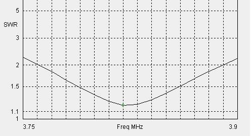
18 40 Meter Rotary Dipole Fiberglass reinforced center section Direct feed 50 ohms VSWR < 1.5:1 typ full band
19 80/75 Meter Sloper One tall support Remotely Switched - 80 to 75 Minimal support side pull


20 80/75 Meter Sloper 3820

21 80/75 Meter Sloper Switch box sits on 20 PVC pole Relay shorts out 6 uh inductor for 75 m
 of my 80m Delta Loop")

22 80/75 Switchbox Located at the bottom (middle) of my 80m Delta Loop Direct feed 50 ohm Relay inserts 10 uh for operation on 80 Folded balun shown


23 40 m 2 el inverted V Hang from catenary between two trees Solid performer at K6AO FD site 5 yrs Dims: 50 ft 30 ft high spacing 25 ft DE ½ L 34 ft Ref ½ L 32 ft Gain ~ 8 dbi
24 20 m 2 el Hammock Spreaders 2 ABS Insulators ½ PVC Wind stable 50 ohm direct feed Gain 10 dbi F/B 16 db


25 20 m 2 el Hammock Good VSWR with no matching Gain: 10 dbi at 30 above ground


26 15 m 2 el Square Boom Quick field assembly K6AO FD site 2007 Self aligning elements Direct feed 50 ohm ½ in aluminum tubing Novel element clamps July 2008 QST Cover Plaque Award winner


27 15 m 2 el Square Boom DE assembly - insulator and balun Reflector assembly EMT clamps


28 15 m 2 el Square Boom Gain >10 dbi, F/B ~ 15 db Direct feed low VSWR
29 Summary - EZNEC Using EZNEC is a fast way to develop or modify antennas. It gives you a feel about what is critical and what is not. You can see interactions between your antennas. The results are generally accurate in the real world. Download the free demo program and get started! FIELD DAY Do a site survey and note available trees or other supports Use Google Earth to measure ground distances Decide on best antennas for the site features
High Performance 40 Meters Vertical Without Radials
 High Performance 40 Meters Vertical Without Radials This shortened easy-to-build vertical, with no-radials, is made from surplus military camouflage poles. It has gain and wave angle comparable to a full-sized
Chapter 6 Antenna Basics. Dipoles, Ground-planes, and Wires Directional Antennas Feed Lines
 Chapter 6 Antenna Basics Dipoles, Ground-planes, and Wires Directional Antennas Feed Lines Some General Rules Bigger is better. (Most of the time) Higher is better. (Most of the time) Lower SWR is better.
ANTENNA DESIGN FOR FREE USING MMANA-GAL SOFTWARE
 ANTENNA DESIGN FOR FREE USING MMANA-GAL SOFTWARE 1. AVAILABLE ANTENNA DESIGN SOFTWARE EZNEC and 4nec2 are based upon the Numerical Electromagnetics Code, or NEC, which is a popular antenna modelling system
The Fabulous Dipole. Ham Radio s Most Versatile Antenna
 The Fabulous Dipole Ham Radio s Most Versatile Antenna 1 What is a Dipole? Gets its name from its two halves One leg on each side of center Each leg is the same length It s a balanced antenna The voltages
Solar Powered Portable Field Day Station. KG5EAO Rick Bono May 28, 2016
 Solar Powered Portable Field Day Station KG5EAO Rick Bono May 28, 2016 Field Day To work as many stations as possible on any and all amateur bands (excluding the 60, 30, 17, and 12-meter bands) and in
A short, off-center fed dipole for 40 m and 20 m by Daniel Marks, KW4TI
 A short, off-center fed dipole for 40 m and 20 m by Daniel Marks, KW4TI Version 2017-Nov-7 Abstract: This antenna is a 20 to 25 foot long (6.0 m to 7.6 m) off-center fed dipole antenna for the 20 m and
Development of a noval Switched Beam Antenna for Communications
 Master Thesis Presentation Development of a noval Switched Beam Antenna for Communications By Ashraf Abuelhaija Supervised by Prof. Dr.-Ing. Klaus Solbach Institute of Microwave and RF Technology Department
Basic Wire Antennas. Part II: Loops and Verticals
 Basic Wire Antennas Part II: Loops and Verticals A loop antenna is composed of a single loop of wire, greater than a half wavelength long. The loop does not have to be any particular shape. RF power can
Antennas! November 2018
 1 Antennas! November 2018 Agenda 6PM Show and Tell plus Demos in the Park 7PM Welcome: new members and visitors Announcements Antenna Overview Alpha Loop Antenna N6IET Vertical Colinear WB6MMQ Whip Dipole
Pacific Antenna 20 and 40M Lightweight Dipole Kit
 Pacific Antenna 20 and 40M Lightweight Dipole Kit Antenna diagram showing configuration and lengths when assembled 7 8 16 9 16 9 Description The Pacific Antenna lightweight dual band dipole kit provides
J-Poles. Mythbusting J-Pole Antennas
 Mythbusting J-Pole Antennas For an antenna to work correctly, it must do two things well 1) Accept power from the feed line impedance match, SWR (ideally) 1:1 2) Radiate power in a pattern that is useful
Portable Vertical Antenna for 75m & 40m
 Portable Vertical Antenna for 75m & 40m BOXBORO August 2012 Jacques VE2AZX Web: ve2azx.net 1 Objectives 1- Portable Antenna for 75m et 40m 2- Low radiation angle for DX 3- Efficient 4- Easy to install.
ANTENNAS Wires, Verticals and Arrays
 ANTENNAS Wires, Verticals and Arrays Presented by Pete Rimmel N8PR 2 1 Tonight we are going to talk about antennas. Anything that will conduct electricity can be made to radiate RF can be called an antenna.
Yagi Antenna Tutorial. Copyright K7JLT 1
 Yagi Antenna Tutorial Copyright K7JLT Yagi: The Man & Developments In the 920 s two Japanese electrical engineers, Hidetsugu Yagi and Shintaro Uda at Tohoku University in Sendai Japan, investigated ways
Beams and Directional Antennas
 Beams and Directional Antennas The Horizontal Dipole Our discussion in this chapter is about the more conventional horizontal dipole and the simplified theory behind dipole based designs. For clarity,
Alpha Delta Communications, Inc. Model DX-OCF Off-Center-Fed 7 Band Antenna
 Alpha Delta Communications, Inc. Model DX-OCF Off-Center-Fed 7 Band Antenna 75/80, 40, 20, 17, 12, 10, and 6 meters (50.0-51.0 MHz) NO TUNER REQUIRED! Installation Instructions One leg is 45 ft., the other
The New and Improved Carolina Windom Antenna and ½ Wave End Fed 20 Meter Vertical and Sloping Wire Antennas. EZNEC analysis by Pete Rimmel, N8PR
 The New and Improved Carolina Windom Antenna and ½ Wave End Fed 20 Meter Vertical and Sloping Wire Antennas EZNEC analysis by Pete Rimmel, N8PR Keeps RF off the Coax below this point / (part of)/ That
Pacific Antenna 20 and 40M Lightweight Dipole Kit
 Pacific Antenna 20 and 40M Lightweight Dipole Kit Diagram showing configuration and approximate lengths 8 3 16 9 16 9 8 3 Description The Pacific Antenna lightweight dual band, trap dipole kit provides
Pacific Antenna 20 and 40M Lightweight Dipole Kit
 Pacific Antenna 20 and 40M Lightweight Dipole Kit Diagram showing configuration and approximate lengths 8 6 16 9 16 9 8 6 Description The Pacific Antenna lightweight dual band, trap dipole kit provides
Coming next: Wireless antennas for beginners
 Coming next: Wireless antennas for beginners In other rooms: Logbook of the World (Sussex Suite) SO2R contest operation (Stable Suite) Wires for your wireless: Simple wire antennas for beginners dominic
A 2 ELEMENT 30 METER PARASITIC VERTICAL ARRAY PROJECT
 A 2 ELEMENT 30 METER PARASITIC VERTICAL ARRAY PROJECT Having killed off the 5B-DXCC purely using LOTW, it was time for the addition of a new band. 30 meters was selected based on lack of sunspots and a
Other Arrays CHAPTER 12
 CHAPTER 12 Other Arrays Chapter 11 on phased arrays only covered arrays made of vertical (omnidirectional) radiators. You can, of course, design phased arrays using elements that, by themselves, already
JK-65 Five Element 6M Yagi
 JK-65 Five Element 6M Yagi PO Box 266, Croton Falls, NY 10519-0266 845.228.8700 (TEL) 845.279.5526 (FAX) info@jkantennas.com Page 1 of 8 JK Antennas Limited Warranty and Liability JK Antennas ( Manufacturer
M2 Antenna Systems, Inc. Model No: 2M4
 M2 Antenna Systems, Inc. Model No: 2M4 SPECIFICATIONS: Model... 2M4 Frequency Range... 144 To 148 MHz *Gain... 9.6 dbi Front to back... 20 db Typical Beamwidth... E=54 H=74 Feed type... T Match Feed Impedance....
Cushcraft. Amateur Radio Antennas LFA-6M5EL. 6 Meter 5 Element Loop Feed Antenna INSTRUCTION MANUAL
 Cushcraft Amateur Radio Antennas LFA-6M5EL 6 Meter 5 Element Loop Feed Antenna INSTRUCTION MANUAL CAUTION: Read All Instructions Before Operating Equipment VERSION 1A Cushcraft Amateur Radio Antennas 308
ANTENNAS. I will mostly be talking about transmission. Keep in mind though, whatever is said about transmission is true of reception.
 Reading 37 Ron Bertrand VK2DQ http://www.radioelectronicschool.com ANTENNAS The purpose of an antenna is to receive and/or transmit electromagnetic radiation. When the antenna is not connected directly
Working Bouvet with the Innovative and Cheap N6MW, Bill Wortman
 Working Bouvet with the Innovative and Cheap N6MW, Bill Wortman Trying to work the upcoming early 2018 Bouvet Dxpedition for an all time new one (ATNO as we say) is a serious challenge for those with only
M2 Antenna Systems, Inc. Model No: KT31WARC
 M2 Antenna Systems, Inc. Model No: KT31WARC SPECIFICATIONS: Model... KT31WARC Frequency Range... 10.1-10.15 MHz **Selectable Frequency Range... 14.0-14.35 MHz **Selectable... (175 KHz / 2:1 VSWR Nominal)
Multiband Vertical Antenna Project 2004 by Harold Melton, KV5R
 2004 by Harold Melton, KV5R Page 1 of 5 Printed 1/14/2004 05:02:00 PM Multiband Vertical Antenna Project 2004 by Harold Melton, KV5R Purpose If you could only have two antennas, what would they be? It
End Fed Half Wave Antenna Coupler
 End Fed Half Wave Antenna Coupler The finished End Fed Half Wave antenna coupler. Centre fed half wave dipoles make great, simple and effective antennas for the HF bands. Sometimes however, the centre
A Reversible Vertical Moxon for 20M
 A Reversible Vertical Moxon for 20M I decided to try a vertical moxon rectangle at my new QTH which has limited rear garden space. The rear garden runs roughly NW to SE, so a reversible moxon gives useful
4/29/2012. General Class Element 3 Course Presentation. Ant Antennas as. Subelement G9. 4 Exam Questions, 4 Groups
 General Class Element 3 Course Presentation ti ELEMENT 3 SUB ELEMENTS General Licensing Class Subelement G9 Antennas and Feedlines 4 Exam Questions, 4 Groups G1 Commission s Rules G2 Operating Procedures
Antennas 101 Don t Be a 0.97 db Weakling! Ward Silver NØAX
 Antennas 101 Don t Be a 0.97 db Weakling! Ward Silver NØAX Overview Antennas 101 2 Overview Basic Antennas: Ground Plane / Dipole How Gain and Nulls are Formed How Phased Arrays Work How Yagis Work (simplified)
Construction Guide: Spiderbeam 40m Add-On Dipole
 6. Spiderbeam 40m Dipole Required Material for Both Versions: Pos QTY Description 1 1210cm Wireman CQ-532 Copperweld Wire 2 986cm Wireman CQ-534 Copperweld Wire 3 210cm Enamel-Insulated Copper Wire 1.5mm
Users Manual. 200W HF/50MHz Band Auto Antenna Tuner. Model HC-200AT
 Users Manual 200W HF/50MHz Band Auto Antenna Tuner Model HC-200AT Caution 1. Never remove or open the tuner cover while transmitting. When there is RF in the circuits of the tuner, there will be high voltage
Antenna Design for FM-02
 Antenna Design for FM-02 I recently received my FM-02 FM transmitter which I purchased from WLC. I researched the forum on what antennas where being used by the DIY community and found a nice write-up
A IVE-BAND, TWO-ELEMENT H QUAD
 A IVE-BAND, TWO-ELEMENT H QUAD Two quad designs are described in this article, both nearly identical. One was constructed by KC6T from scratch, and the other was built by Al Doig, W6NBH, using modified
M2 Antenna Systems, Inc. Model No: 20M6-125
 M2 Antenna Systems, Inc. Model No: 20M6-125 SPECIFICATIONS: Model... 20M6-125 Frequency Range... 14.0 14.350 MHz *Gain, (FS) / Over gnd... 11.19dBi / 16.6dBi @70 Front to back... 25 db Typical Beamwidth...
USERS MANUAL for the. FB5 Antenna. a personal non-commercial project of the Florida Boys
 USERS MANUAL for the FB5 Antenna a personal non-commercial project of the Florida Boys AB4ET Dec.2003 1 The FB5 Antenna USERS MANUAL INDEX 1.0. Introduction 2.0. Design 3.0. Construction 4.0. Electrical
I recently came across a No-Counterpoise antenna described by designed by Peter Millis M3KXZ and based on an original design by K9ESE.
 M3KXZ 'no counterpoise' antenna I recently came across a No-Counterpoise antenna described by designed by Peter Millis M3KXZ and based on an original design by K9ESE. Details of the antenna can be found
Tuned Loop Antenna 20 through 10 meters
 Tuned Loop Antenna 20 through 10 meters - Revised: 2015-11-06 At K0MPH, a tuned loop antenna is used on the 20, 15 and 10 meter bands. I was inspired by George Badger, February 2008 QST - The W6TC DX Loop,
6 MTR 4 EL SIX BAND QUAD. Bob Hume KG6B AUG 23, 2004
 6 MTR 4 EL SIX BAND QUAD Bob Hume KG6B AUG 23, 24 This paper is an extension of a prior paper titled "Design of a Five Band Quad and Its Coax Feed System" which described a large 4 EL (5 EL on 1 Meters)
M2 Antenna Systems, Inc. Model No: 20M5LD
 M2 Antenna Systems, Inc. Model No: 20M5LD SPECIFICATIONS: Model... 20M5LD Frequency Range... 14.0 14.350 MHz *Gain (Full Band)... 10.2 dbi Typical Front to back... 23 db Typical Beamwidth... E=50 / H=66
Remote Controller. (Controller: Provided in kit form) * Power Supply Required: Approx. 13VDC 0.2~0.4A (Not Required for CD160Jr)
 * Power Supply Required: Approx. 13VDC 0.2~0.4A (Not Required for CD160Jr)") 1.8MHz(3-CH),1.9MHz(1-CH) 1.8/1.9MHz Super-Compact Dipole Antenna CD160-x, CD160L Model CD160 Antenna Tuning Unit BS83 Remote Controller (Controller: Provided in kit form) * Power Supply Required: Approx.
1.8MHz(3-CH),1.9MHz(1-CH) 1.8/1.9MHz Super-Compact Dipole Antenna CD160-x, CD160L Model CD160 Antenna Tuning Unit BS83 Remote Controller (Controller: Provided in kit form) * Power Supply Required: Approx.
M2 Antenna Systems, Inc. Model No: 2M7
 M2 Antenna Systems, Inc. Model No: 2M7 SPECIFICATIONS: Model... 2M7 Frequency Range... 144 To 148 MHz *Gain... 12.3 dbi Front to back... 20 db Typical Beamwidth... E=43 H=50 Feed type... T Match Feed Impedance....
TZ-RD-1740 Rotary Dipole Instruction Manual
 TZ-RD-1740 17/40m Rotary Dipole Instruction Manual The TZ-RD-1740 is a loaded dipole antenna for the 40m band and a full size rotary dipole for the 17m band. The antenna uses an aluminium radiating section
9el 144MHZ LFA YAGI ASSEMBLY & INSTALLATION MANUAL
 1 9el 144MHZ LFA YAGI ASSEMBLY & INSTALLATION MANUAL 2 WARNING EXTREME CAUTION SHOULD BE TAKEN WHEN CONSTRUCTING AND ERECTING ANTENNA SYSTEMS NEAR POWER AND TELEPHONE LINES. SERIOUS INJURY OR DEATH CAN
Antennas Demystified Antennas in Emergency Communications. Scott Honaker N7SS
 Antennas Demystified Antennas in Emergency Communications Scott Honaker N7SS Importance of Antennas Antennas are more important than the radio A $5000 TV with rabbit ears will have a lousy picture Antennas
CHAPTER 8 ANTENNAS 1
 CHAPTER 8 ANTENNAS 1 2 Antennas A good antenna works A bad antenna is a waste of time & money Antenna systems can be very inexpensive and simple They can also be very expensive 3 Antenna Considerations
M2 Antenna Systems, Inc. Model No: 10-30LP8
 M2 Antenna Systems, Inc. Model No: 10-30LP8 VSWR 2:1 TYPICAL VSWR @ 70 FT. 2:1 1.5:1 1.5:1 1.2:1 1.2:1 10 14 MHz 11 12 13 17 15 16 18 19 20 21 22 23 24 25 26 27 28 29 30 SPECIFICATIONS: Model...10-30LP8
Cray Valley Radio Society. Real Life Wire Antennas
 Cray Valley Radio Society Real Life Wire Antennas 1 The basic dipole The size of an antenna is determined by the wavelength of operation In free space: ~3x10 8 m/s Frequency x Wavelength = Speed of Light,
ANTENNA BASICS FOR BEGINNERS
 ANTENNA BASICS FOR BEGINNERS PART 2 -DIPOLES DIPOLES -General MULTIBAND DIPOLES RF CHOKES 1 DIPOLES Several different variations of the dipole are also used, such as the folded dipole, short dipole, cage
HOW TO BUILD A THREE LEG TERMINATED DIPOLE T3FD COVERING
 HOW TO BUILD A THREE LEG TERMINATED DIPOLE T3FD COVERING 160 10Meters Tony KA2UFO 8/2018 REV 1.0 8/29/2018 Tony KA2UFO 8/2018 Page 1 Introduction Presented here are design and build notes for a Three Leg
Directive Systems & Engineering 2702 Rodgers Terrace Haymarket, VA
 Directive Systems & Engineering 2702 Rodgers Terrace Haymarket, VA 20169 1628 www.directivesystems.com 703 754 3876 K1JX DESIGNED 6 ELEMENT 50 MHZ YAGI, DSEJX6 50 INTRODUCTION The Directive Systems DSEJX6-50
Nick Garner N3WG and George Zafiropoulos KJ6VU
 Nick Garner N3WG and George Zafiropoulos KJ6VU Introduction Over the last few years, there has been a significant increase in the number of radio amateurs interested in portable operating. This is due
W6NL Moxon on Cushcraft XM240
 W6NL Moxon on Cushcraft XM240 0 db = 10.73 dbi 7.050 MHz 2.00 99.5% Efficiency High F/B 300+ khz VSWR BW SWR 1.50 1.00 7 7.1 7.2 7.3 MHz - 1 - Construction of W6NL Moxon on Cushcraft XM240 Dave Leeson,
Newcomers And Elmers Net: Wire Antennas Robert AK3Q
 Newcomers And Elmers Net: Wire Antennas 02-07-16 Robert AK3Q Wire antennas represent one of the greatest values in the radio hobby world. For less than the cost of a good meal out on the town you can buy
TBARC Programs Antenna Modeling with 4NEC2. By Randy Rogers AD7ZU 2010
 TBARC Programs Antenna Modeling with 4NEC2 By Randy Rogers AD7ZU 2010 Getting Started 4NEC2 is a completely free windows based tool suite to aid in the design and optimization of antenna systems 4NEC2
M2 Antenna Systems, Inc. Model No: 2M5WL
 M2 Antenna Systems, Inc. Model No: 2M5WL SPECIFICATIONS: Model... 2M5WL Frequency Range... 144 To 148 MHz *Gain... 16.84 dbi Front to back... 22 db Typical Beamwidth... E=26 H=29 Feed type... T Match Feed
# -antenna (hash) 4 direction switchable array
 4 direction switchable array") # -antenna (hash) 4 direction switchable array Feasibility study Paper on CCF & OHDXF cruise 4.1.2012 Pekka Ketonen 4.2.2012 OH1TV 1 4 direction, instant switching 4.2.2012 OH1TV 2 Features Instant direction
# -antenna (hash) 4 direction switchable array Feasibility study Paper on CCF & OHDXF cruise 4.1.2012 Pekka Ketonen 4.2.2012 OH1TV 1 4 direction, instant switching 4.2.2012 OH1TV 2 Features Instant direction
Connecting Your Rig To The Aether
 Connecting Your Rig To The Aether 1 Ward Harriman (AE6TY) Pacificon 18 1: of course, there is no Aether! Presentation Goals Review a common design to reinforce forgotten knowledge. Use that design to demonstrate
A fool with a tool is still a fool. Measurements of an antenna loading coil by Frank F/N4SPP
 A fool with a tool is still a fool Measurements of an antenna loading coil by Frank F/N4SPP I have constructed a center-loaded mini-dipole, and used two of those to create a 2-element mini yagi beam antenna.
Design of a Delta Loop September 26, 2016
 Design of a Delta Loop September 26, 2016 by K0ZR Introduction Why a Delta loop? A Delta loop can be made to radiate a horizontal or vertically polarized signal. In most cases one chooses the vertical
The Long Wire Loop: an Omnidirectional, Multiband, Low Angle Radiator. By Steve Cerwin, WA5FRF
 The Long Wire Loop: an Omnidirectional, Multiband, Low Angle Radiator By Steve Cerwin, WA5FRF Introduction: Something Old and Something New As the name implies, long wire loop is a marriage of the venerable
What is a BALUN or UNUN:
 What is a BALUN or UNUN: A device to connect different types of antennas to various feed lines. Can transform impedances, choke common mode or change balanced to unbalanced BALUN Balanced to Unbalanced
Traveling Wave Antennas
 Traveling Wave Antennas Antennas with open-ended wires where the current must go to zero (dipoles, monopoles, etc.) can be characterized as standing wave antennas or resonant antennas. The current on these
INSTRUCTION MANUAL VB-66DX. 6-Meter 6-Element Beam. Preparation For Assembly. General Description
 VB-66DX 308 Industrial Park Road Starkville, MS 39759 USA Ph: (662) 323-9538 FAX: (662) 323-6551 6-Meter 6-Element Beam INSTRUCTION MANUAL General Description The Hy-Gain Model 66DX is a full sized 6-
Portable HF Antennas. Think Like A Backpacker. George - KJ6VU
 Portable HF Antennas Think Like A Backpacker George - KJ6VU WWW. HAMRADIO360.COM WWW. PACKTENNA.COM PODCAST www.kj6vu.com My Personal Goals Operate more HF Get out and hike more Improve my CW skills Build
M2 Antenna Systems, Inc. Model No: 436CP30
 M2 Antenna Systems, Inc. Model No: 436CP30 SPECIFICATIONS: Model... 436CP30 Frequency Range... 432 To 440 MHz *Gain... 15.50 dbic Front to back... 18 db Typical Elipticity... 1.5 db Typical Beamwidth...
Build a 12/17 Meter Trap Dipole Phil Salas AD5X
 Build a 12/17 Meter Trap Dipole Phil Salas AD5X Introduction Why a 12/17 meter rotatable dipole? Well, many folks have verticals for the lower bands, and multi-band dipoles or beams for 20-, 15-, and 10
AD5X. The 43-Foot Vertical. Phil Salas - AD5X Phil Salas AD5X. Richardson, Texas
 The 43-Foot Vertical Phil Salas - AD5X ad5x@arrl.net Outline Why a vertical? Ground Losses and Antenna Efficiency Why a 43-foot vertical? SWR-related coax and unun losses Matching Networks for 160- and
General Product Brochure
 General Product Brochure SteppIR Antennas 2112 116th Ave NE #1-5 Bellevue, WA 98004 Tel: 425.453.1910 sales@steppir.com www.steppir.com SteppIR - Why Compromise? The SteppIR antenna was conceived to solve
EH-20 20m antenna. By VE3RGW
 EH-20 20m antenna By VE3RGW Equivalent circuit of EH-20 antenna system. Upper cylinder Lower cylinder Phasing coil Common mode radiator Tune coil RF choke or 14MHz trap 50ohm coaxial cable 0-150pF (case
BUILD A HIGH PERFORMANCE TWO ELEMENT TRI-BAND CUBICAL QUAD. By Bob Rosier K4OCE INTRODUCTION THEORY AND GENERAL INFORMATION
 BUILD A HIGH PERFORMANCE TWO ELEMENT TRI-BAND CUBICAL QUAD INTRODUCTION By Bob Rosier K4OCE Lots of DX can be worked with a dipole at the QRP level, however, a beam will obviously give you additional gain
Jacques Audet VE2AZX. Nov VE2AZX 1
 Jacques Audet VE2AZX VE2AZX@amsat.org Nov. 2006 VE2AZX 1 - REASONS FOR USING A BALUN - TYPES OF BALUNS - CHECK YOUR BALUN WITH AN SWR ANALYZER - MEASURING THE IMPEDANCE OF A NUMBER OF FERRITES - IMPEDANCE
The Vertical Buddi Beam on 20m using no Coils.
 The Vertical Buddi Beam on 20m using no Coils. design by Lou Rummel KE4UYP In this article I am going to describe a totally new way to construct and use a very old design the two element Yagi antenna.
Install as much wire/tubing as possible Electrically short antennas Minimize matching losses Good ground for verticals Maximizes antenna efficiency
 Jim Wolf KR9U Install as much wire/tubing as possible Electrically short antennas Minimize matching losses Good ground for verticals Maximizes antenna efficiency Far-away ground conditions determine low
General License Class Chapter 6 - Antennas. Bob KA9BHD Eric K9VIC
 General License Class Chapter 6 - Antennas Bob KA9BHD Eric K9VIC Learning Objectives Teach you enough to get all the antenna questions right during the VE Session Learn a few things from you about antennas
One I had narrowed the options down, I installed some wire and started testing.
 Loft & Attic antennas for restricted spaces - M. Ehrenfried G8JNJ I ve recently been looking at designs for an efficient antenna that would fit in a loft. I hoped to find something that would work on with
N5PUV s 4 Band Fan Dipole Experiment. Using the New SRI (Stanford Research Institute) Method
 Method") N5PUV s 4 Band Fan Dipole Experiment Using the New SRI (Stanford Research Institute) Method Goals of Experiment Develop a Multi-band Antenna that does NOT require a tuner Build using the new, easier tuning
N5PUV s 4 Band Fan Dipole Experiment Using the New SRI (Stanford Research Institute) Method Goals of Experiment Develop a Multi-band Antenna that does NOT require a tuner Build using the new, easier tuning
6M HALO VERSON II + OPTIONAL 2M GROUND PLANE
 The halo is an omnidirectional, horizontally polarized antenna with about the same gain as a dipole but without the low elevation nulls off the ends (+5.5 to +3.5dBi variation for the Halo vs. +7.9 to
DB Duo-Monoband Beam 7 - Element, 12 and 17 Meter INSTRUCTION MANUAL. General Description
 308 Industrial Park Road Starkville, MS 39759 USA Ph: (662) 323-9538 FAX: (662) 323-6551 DB- 1217 Duo-Monoband Beam 7 - Element, 12 and 17 Meter INSTRUCTION MANUAL General Description The Hy-Gain DB-1217
Tuning a 160M full sized vertical with strong AM broadcast RF present on the antenna. Jay Terleski, WX0B
 Tuning a 160M full sized vertical with strong AM broadcast RF present on the antenna. Jay Terleski, WX0B I often get asked about how to match a ¼ WL vertical to a 50 ohm transmission line and what to do
Weekend Antennas No. 5 The "Compact Quad" Multiband Antenna
 Weekend Antennas No. 5 The "Compact Quad" Multiband Antenna When I relocated to Johannesburg I needed a new multiband HF antenna. Since I was staying in a rented house a tower was out of the question,
Resonant Antennas: Wires and Patches
 Resonant Antennas: Wires and Patches Dipole Antennas Antenna 48 Current distribution approximation Un-normalized pattern: and Antenna 49 Radiating power: For half-wave dipole and,, or at exact resonance.
M2 Antenna Systems, Inc. Model No: 435XP50
 M2 Antenna Systems, Inc. Model No: 435XP50 SPECIFICATIONS: Model... 435XP50 Frequency Range... 430 To 436 MHz *Gain... 19.2 dbi Front to back... 22 db Typical Cross pol. isolation... >20 db Typical Beamwidth...
M2 Antenna Systems, Inc. Model No: 10-30LP8
 M2 Antenna Systems, Inc. Model No: 10-30LP8 SPECIFICATIONS: Model... 10-30LP8 Frequency Range... 10-30 MHz Continuous *Gain free space / 65... 5.2 dbi / 10.5 dbi 10-30 Front to back... 15 db 10-30 MHz
M2 Antenna Systems, Inc. Model No: 40M3L
 M2 Antenna Systems, Inc. Model No: 40M3L SPECIFICATIONS: Model... 40M3L Frequency Range... 7.0-7.3 MHz X 150 khz Gain... 6.6 dbi Front to back... 23 db Beamwidth... E=62 Feed type... Hair pin match Feed
Antenna? What s That? Chet Thayer WA3I
 Antenna? What s That? Chet Thayer WA3I Space: The Final Frontier Empty Space (-Time) Four dimensional region that holds everything Is Permeable : It requires energy to set up a magnetic field within it.
Title: Four-Square Phased Array for Receiving Date: March 19, 2013 Reference: Low-Band DXing, Hi-Z Antennas, DX Engineering
 Background Written and internet resources are available to provide the needed background necessary to design and build your own four-square receiving array. Several commercial systems are available, however
M2 Antenna Systems, Inc. Model No: 450CP34
 M2 Antenna Systems, Inc. Model No: 450CP34 SPECIFICATIONS: Model... 450CP34 Frequency Range... 435 To 455 mhz *Gain... 16.0 dbi Front to back... 22 db Typical Beamwidth... 28 Circular Feed type... T Match
NVIS, Another Look. Tom Sanders, W6QJI Ed Bruette, N7NVP
 NVIS, Another Look Tom Sanders, W6QJI Ed Bruette, N7NVP Regional Communications N.V.I.S. Near Vertical Incidence Skywave What is NVIS? Near Vertical Incident Skywave Cloud Warmer Propagation Theory NVIS
AD5X. Low Cost HF Antennas & Accessories. Phil Salas - AD5X Phil Salas AD5X. Richardson, Texas
 Low Cost HF Antennas & Accessories Phil Salas - AD5X ad5x@arrl.net PVC Tubing PVC pipe: Considers the inside diameter (ID) of the pipe. For PVC pipe (schedule 40): 1/2" PVC pipe has an ID of 0.6" and an
2-element Single Mast Wire Beam with 4 Switchable Directions
 2-element Single Mast Wire Beam with 4 Switchable Directions Chavdar Levkov Jr. LZ1ABC, ch.levkov@gmail.com, Chavdar Levkov LZ1AQ, lz1aq@abv.bg We need a directional antenna field day style for 20 m band.
WHY YOU NEED A CURRENT BALUN
 HF OPERATORS WHY YOU NEED A CURRENT BALUN by John White VA7JW NSARC HF Operators 1 What is a Balun? A BALUN is a device typically inserted at the feed point of a dipole-like antenna wire dipoles, Yagi
FAST MAST ANTENNA SYSTEM
 FAST MAST ANTENNA SYSTEM FAST DEPLOYMENT RECEIVER HITCH 25 ANTENNA TOWER DEPLOY YOUR ANTENNA SYSTEM IN LESS THAN 5 MINUTES THE EXTENDS FROM 7.5 FT UP TO 25 FT OR ANY POINT INBETWEEN. CONSTRUCTED FROM HEAVY
How to Blow Up Your Balun
 How to Blow Up Your Balun (and other things too ) By Dean Straw, N6BV Sea-Pac June 7, 2014 Photos courtesy Jim Brown, K9YC 1 This is What I Intend to do Today I will examine stresses placed on common-mode
G3EJS portable antenna for the IC-703
 G3EJS portable antenna for the IC-703 Following a comment I have received several emails reqesting details of my antenna, so I have very quickly put this together, not very good, but sufficient for anyone
simple and robust feeding system. No phasing lines or matching devices to worry about. spiderbeam on 10m aluminium push-up pole
 The spiderbeam was developed as a DXpeditioner's dream antenna. It is a full size lightweight tribander yagi made of fiberglass and wire. The whole antenna weight is only kg (lbs), making it ideally suited
M2 Antenna Systems, Inc. Model No: YAGI ANTENNA
 M Antenna Systems, Inc. Model No: 4.5-7 YAGI ANTENNA SPECIFICATIONS: Model... 4.5-7 Frequency Range... 4.0 To 4.5 MHz *Gain... 0 To 7 dbi Front to back... 0 db over the rear 80 Beamwidth... E=44 H=50 typical