Team USAS CDR. Tom Bateman Barry Blakeley Adam Dean Jake Hanft Mike Sheek. Team USAS CDR 1
|
|
|
- Edwin Cobb
- 5 years ago
- Views:
Transcription
1 Team USAS CDR Tom Bateman Barry Blakeley Adam Dean Jake Hanft Mike Sheek Team USAS CDR 1
2 Presentation Overview Status of RFA s System Architecture Mechanical Design Elements Electrical Design Elements Software Design Elements Verification and Test Plans Project Management Team USAS CDR 2
3 Status of RFA s from PDR RFA Rationale Response Include a goal of a testbed with a validated model Provide additional capabilites of already existing COTS UAV stability systems Added the requirement of a simulated model of our system for test predictions and comparisons Revisit the dynamic range for data storage. Make sure the verification needs are met with low dynamic range 8 bytes = 1/256 MSB resolution. (Dynamics Usually > Bits) Made necessary adjustments for data storage needs Team USAS CDR 3
4 System Architecture Adam Dean Team USAS CDR 4
5 System Architecture Overview of Objectives USAS Goal Provide artificial pitch-rate damping for small UAV with the use of a microcontroller interfaced with a sensor package and the pitch control servo. The system will provide capability similar to existing stabilization gyro packages, with additional features and flexibility, such as in-flight gain control Team USAS CDR 5
6 System Architecture Overview of Requirements SAS Requirement Quantity Reason Artificial Pitch Axis Damping equivalent to 10% SM Primary Goal Inflight Command Override Return C.G. to full frontal position/ Disable Safety SAS Limited Control Authority ~ 10% Safety System Response Time ~ 10ms Airplane Pitch Bandwidth ~ 10Hz Automatic System Recovery Time << 250ms Pilot Reaction Time Data Sampling Rate >> 50 Hz Servo PRF Data Resolution >= 8 bit Max Servo Resolution Team USAS CDR 6
7 System Architecture Overview of Requirements Test Bed Aircraft Requirements changes since PDR are highlighted Requirement Quantity Reason Size (Generic) 0.60 in^3 Low cost/performance Wing Loading oz/ft^2 Flying qualities / Stall Speed TOGW 15 lb Max Flying qualities / Stall Speed / Payload Wingspan 72 in Size / Wing Loading Propulsion Electric Reduced noise & vibration, clean Payload Capacity (Electronics) 2.5 lb / 90 in^3 (PDR lb / 206 in^3) Electronics Payload Moveable CG +10% - 0% SM Testing Team USAS CDR 7
8 System Architecture Overview of Requirements Simulations Requirements changed since PDR are highlighted Requirement Reason Flight Dynamics Model Simulate the expected system response for test predictions and comparison to actual system data Aid in the design of control algorithm Wing Structural Model Insure the performance capablities of the aircraft Control System Software Simulation Validation of control software functionality prior to flight Team USAS CDR 8
9 System Architecture System Design SAS SAS System Element Purpose Quantity Reason Rate Gyro Measures the pitch rate of the airplane deg/s Control system calculations and algorithms Accelerometer Measures the airplane acceleration in the pitch axis g Control system calculations and algorithms Pressure Transducer Measure dynamic pressure with pitot-static tube 0-1 psi Calculate airspeed - used in the control system s software Microchip PIC1854F CPU Data processing Data Storage Storage of the measured flight quantities, pilot input, and control system output in flight 275 kb Testing, verification and data analysis Pilot Signal Transmission Gives the proper flight commands to the flight control system Command override Controller Signal Transmission Controls the movement of the c.g. apparatus and in-flight gain of the SAS Reduced pilot workload Team USAS CDR 9
10 System Architecture System Design Test Bed Aircraft Aircraft Characteristics Design Engine Type Electric Size 0.60 in^3 Wing Span 84 in. Wing Loading 37 oz/ft^2 Airfoil Root -S4233, Tip -SD7062 Material Fiberglass Composite Total Weight 13.5 lb +/- 5% Payload Capacity Electronics 90 in^3 Batteries 40 in^3 Avionics 52 in^3 Total 177 in^3 Structure Fiberglass Composite Shell w/ Plywood Bulkheads Fuselage Integrated Aluminum Backbone Modularity Moveable C.G. Adjustable Tail Volume Integrated Backbone Team USAS CDR 10

11 Team USAS CDR 11
12 System Architecture System Design C.G. Apparatus Parameter Relevant Specification Objective Notes Moveable Weight 1.08 lbs Attain +10% - 0% SM SM is linearly related to slew of Balance Weight Total Longitudinal Movement 11.5 in Attain +10% - 0% SM Use gear rack and pinion design to move apparatus Control Servo Futaba Sail-Winch Servo Torque oz-in Speed rad/s Max Revolutions - 6 Torque / Speed Gear wheel radius -.75 Needed revolutions Max Travel Time s Slide Mechanism 3/8 Diameter radial bearings Prevent apparatus from sticking Bearings will slide in grooves cut in backbone Position Measurement Servo Feedback Measurement Data Acquisition Eliminate need for external sensor Team USAS CDR 12
13 System Architecture Verification Analysis SAS Simulink model of simulated dynamic response Test Bed Aircraft Flying qualities determination spreadsheet C.G. location/manipulation stability spreadsheet Static wing loading simulation, test, and analysis Technology Demonstrator Aircraft (TDA) flight Team USAS CDR 13
14 Mechanical Design Elements Mike Sheek / Tom Bateman Team USAS CDR 14
15 Mechanical Design Outline Drawing Tree Stability Analysis Stability Configurations CG Apparatus Adjustable Tailboom Fuselage Design Wing Design Weight Analysis Team USAS CDR 15
16 Mechanical Design Elements Drawing Tree Team USAS CDR 16
17 UAV Stability Configurations Difference in positions of horizontal stabilizer with reference to wing root c/4 C r / 4 C rtail / 4 c Total distance traveled by moveable CG apparatus M_CG loc Forward Tail loc Aft Static Margin 10.0% CG aft of cr/4 (in) 2.49 Moveable CG wgt = 1.08 lb Aft Aft 0.0% 3.41 Forward Forward 5.7% 2.26 Aft Forward -4.3% 3.17 Team USAS CDR 17

18 CG Control Apparatus Backbone Roller Track Shuttle Assembly Limit Stop Rack Gear Ball Bearing Rollers Drive Servo Servo Battery Team USAS CDR 18

19 CG Control Apparatus (cont) Bearing Shaft Spur Gear Drive Servo Spacer Ball Bearing Roller Shuttle Frame Team USAS CDR 19

20 Adjustable Tailboom Stabilizer Vertical Fin Tailboom Backbone Rudder Servo Elevator Servo Tailboom Adapter Team USAS CDR 20


21 Fuselage Design Effectively integrate backbone concept to fuselage design Create non-structural fuselage shell with minimum weight Connect all components directly to backbone for structural support Lighten fuselage by ~20% from TDA Team USAS CDR 21

22 Nose Section Cutaway Electric Powerplant Control Linkage Main Battery 15x6 Propeller Backbone NWS Servo Nose gear Strut Nose gear Mount Team USAS CDR 22

23 Wing Design & Construction Team USAS CDR 23
24 Structural Design Normal Bending Moment Distribution M, lb-ft Spanw ise Station Distributed Load Approximated (test) Load Point Load at Tip Team USAS CDR 24

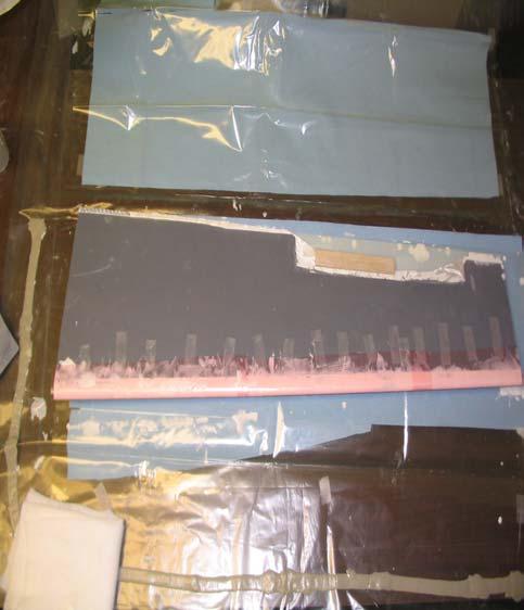
25 Wing Structural Load Test Digital pull scales Elastic bands Support structure Load straps Tip support Holding Jig Team USAS CDR 25

26 Wing Structural Load Test Wing Panel Under Fully Applied Load Team USAS CDR 26

27 Aileron Servo & Pitot-Static Probe Access Pitot-Static Probe Servo Bay Control Linkage Aileron Servo Access Panel / Servo Mount Team USAS CDR 27
28 Test Bed Weight Analysis Aircraft Subsystem Weight (kg) Weight (lb) Weight % Power plant Batteries % Wing % Fuselage / Backbone % Electric Power plant % Electronics % Moveable CG Apparatus % Tail % Landing Gears % Total % Team USAS CDR 28
29 Electrical Design Elements Jake Hanft Team USAS CDR 29

30 Electrical Design Elements Block Diagrams Microcontroller PIC18F458 Rate Gyro Pressure Transducer Electrical Schematics Chassis Power Analysis QuikFlash Board Data Acquisition Accelerometer Team USAS CDR 30
31 Controller Board Block Diagram PROCESS INTERRUPT PITCH DYNAMIC Z-AXIS DATA SWITCH RATE PRESSURE ACCELERATION PITCH COMMAND CG CONTROL GAIN CONTROL PWMD PWMD PWMD 0/1 A/D A/D A/D 0/1 A/D A/D A/D MICROCONTROLLER VDD 0/1 PWM A/D PWM A/D 0101 PITCH FEEDBACK CG CONTROL FEEDBACK PITCH COMMAND CG COMMAND COMMAND OVERRIDE V REF REG DATA ACQUISITION (EXTERNAL EEPROM (512k)) Legend POWER 6-9 VDC COMMANDS SENSORS V REF FEEDBACK OUTPUTS Team USAS CDR 31
32 Command Override Process PWM (C/O Signal) LPF 0.1 or 0.2 V + COMPARATOR - Digital Output (1/0) I/O Pin Vref (0.15 V) Team USAS CDR 32
33 PWM Decoder Process PWM + - LPF One-Shot Control Voltage Team USAS CDR 33
34 Sensor Board Block Diagram Rate LPF Out1 Filter, SF, Zero g offset VDC Accel LPF Out2 Pressure LPF Out3 Team USAS CDR 34
35 SAS Schematic Team USAS CDR 35
36 Sensor Board Schematics Team USAS CDR 36
37 Power Analysis Power Breakdown Standard 9 Volt battery ~ 200mAh 1/2 hour of flight time Bench testing required for regulator operation Component Microcontroller (PIC18F458) Rate Gyro (ADXRS150) Accelerometer (ADXL 150) Pressure Transducer (SDX Series) Voltage Regulator (LM340T-5.0) Operating Voltage Range (V) Current Draw (ma) to (8.0 Max) 4 to (3.0 Max) < 20 < Vin 20 8 Total 5 <300 Team USAS CDR 37
38 Data Acquisition Specification Parameter goal Reason Notes Sampling Rate > 50 Hz Servo PRF Resolution 10 bit ADC Resolution Minimum Channels 8 Signals to be monitored 1 Pilot Elevator Command Calculated Output Command 2 Pitch Rate CH No. 3 4 Control System Output Airspeed 5 CG Position 6 Gain Control 7 Pitch Feedback 8 CG Control Feedback Minimum Sampling Time 300s 1/2 Flight Duration Estimated endurance 10 min Minimum Storage Capacity 275kB 50Hz x 9ch x 300s x 2 byte/data point Team USAS CDR 38
39 System Noise Analysis Possible Sources of Noise Component System Input Plan of Action May have khz of noise during flight Propeller Engine Brushes 10,000 rpm 10 x rpm (100,000) Test system with engine on and off Vibrational Noise Pressure Noise ~10 khz ~10 khz Filter accordingly Team USAS CDR 39
40 Software Design Elements Tom Bateman Team USAS CDR 40
41 Control Process Flow Start (power on) Z-axis acceleration Dynamic pressure Pitch rate A/D A/D A/D Initialize variables Watchdog/ Brownout Bypass CG control Estimate commanded pitch rate 0/1 Data switch Pilot command Gain control CG control PWM PWM PWM Read sensor inputs Read command inputs Timing Loop Compute PR error Apply control gain Primary Control Algorithm Command override 0/1 Read feedback inputs Compute elevator deflection Elevator servo CG Servo Data switch A/D A/D 0/1 Command Override? Y Bypass pitch control N Apply SAS Authority Limiting Output elevator control signal PWM Pitch command CG command PWM Command CG to full forward 0101 Output data External acquisition EEPROM Team USAS CDR 41
42 Primary Control Algorithm Pseudo Code STEP DESC I/O IN / OUT TYPE QTY UNITS 1 Read pitch rate RG IN A/D bin 2 Read z acceleration ACC IN A/D bin 3 Read dynamic pressure PT IN A/D bin 4 Read PC servo feedback signal FB_P IN A/D bin 5 Read CG servo feedback signal FB_CG IN A/D bin 6 Read PC pilot command CMD_P IN A/D bin 7 Read CG position command CMD_CG IN A/D bin 8 Read gain control CMD_G IN A/D bin 9 Read command override state CMD_CO IN DIG 0, 1 bool 10 Read data acquisition state CMD_DA IN DIG 0, 1 bool 11 Scale pitch rate deg/s 12 Scale z acceleration g 13 Convert dynamic pressure to indicated airspeed ft/s 14 Convert PC feedback signal to position deg 15 Convert CG feedback to longitudinal position in 16 Convert pilot command to commanded position deg 17 Convert CG command to commanded position in 18 Convert gain control to numerical gain TBD Team USAS CDR 42
43 Primary Control Algorithm Pseudo Code STEP PROCESS NOTES 1 Compute estimated alpha az*2*w/(g*rho*v^2*a) = alpha 2 Compute SAS commanded elevator deflection scale factor 3 Estimate tail downwash lookup table or scale factor and alpha 4 Compute tail moment contribution flight mechanics 5 Compute wing moment contribution flight mechanics 6 Compute angular acceleration alpha_dot_dot = M / I 7 Integrate to find pitch rate Euler integration: d_alpha dot = alpha_dot_dot * dt 8 Compare computed PR to measured PR 9 Apply proportional gain to PR error 10 Differentiate measured pitch rate to find angular acceleration dpr / dt 11 Compare measured AA to computed AA 12 Apply derivative gain to AA error 13 Compute elevator deflection error 14 Apply elevator correction to pilot command 15 Output elevator command signal Team USAS CDR 43
44 Testing of Control Algorithm - Simulink Team USAS CDR 44
45 Simulink Model (Detail) Team USAS CDR 45

46 System Dynamic Response System Off Step Input System On System Off Turbulence System On Team USAS CDR 46
47 Simulink Model Final model will include: Random processes simulating system noise Individual sensor inputs Simulated pilot input through random process implementation Detailed control algorithm based off of aircraft dynamics and control models Team USAS CDR 47
48 Additional Testing of Software Complete hardware mock set-up Initiate disturbances to fuselage and tail assembly Analyze data to see system response Team USAS CDR 48
49 SAS Latency Analysis Include analysis based off of processor speed and estimated number of commands Team USAS CDR 49
50 Integration Plan Tom Bateman Team USAS CDR 50
51 Unit Test Plan Major Task Description Primary Goal Deliverables Basic Microcontroller (MC) Operations Perform basic I/O operations on the PIC18F4xx, including digital I/O, A/D input, PWM output and memory writes Familiarization Test and verify MC implementation of digital I/O, ADC, and PWM capabilities Advanced MC operations Perform PWM servo feedback control tests PWM input and output, ADC input, R/C Receiver interfacing, performance analysis Operate R/C controls with MC in the loop Sensors and signal conditioning Perform bench tests of sensors, determine signal conditioning requirements Familiarization, signal conditioning design Test and verify sensor outputs, signal ranges, SNR's, and signal conditioning hardware Advanced sensor operations Calibrate and test sensors in field environment, using PIC interface Unit test of sensors, flight certification Test and verify operation of MC and sensor package in flight Programming Write individual signal processing and control blocks Code development Test and verify operation of real time control software modules Support Operations Develop critical subsystems, such as command override processing, power conditioning, backup systems Electronic hardware design Develop, test, and verify operation of all necessary electronic hardware support elements Manufacturing Quality Control Implement quality assurance on critical airframe components Flight safety, mission performance Test and verification data on critical components, such as wing Evaluation Flight Testing Shakedown flight testing of airframe Pilot familiarization, aircraft trim adjustments, evaluation of flying qualities Qualitative flight test analysis Specification Flight Testing Detailed flight test of airframe Establish baseline aircraft performance characteristics All aircraft performance parameters applicable to SAS verification testing Structured Research Build and test individual sensor subsystems in ASEN 4519 Resource management Perform measurements with primary sensors using MC Team USAS CDR 51
52 Verification and Test Plans Barry Blakeley Team USAS CDR 52
53 Verification and Test Plans Systems to verify UAV flying qualities SAS performance Alternative test Team USAS CDR 53
54 Verification of Flying Qualities Hypothesis UAV will qualify at Level 1 or Level 2 on a modified Cooper-Harper scale Pilot compensation not a factor for desired performance. Team USAS CDR 54
55 Verification of Flying Qualities Pilot Rating Scale Rating Aircraft Characteristics Excellent highly desirable Good negligible deficiencies Fair some mildly unpleasant deficiencies Minor but annoying deficiencies Moderately objectionable deficiencies Very objectionable but tolerable deficiencies Major deficiencies Major deficiencies Major deficiencies Major deficiencies Demands on the Pilot Pilot compensation not a factor for desired performance Pilot compensation not a factor for desired performance Minimum pilot compensation required for desired performance Desired performance requires moderate pilot compensation Adequate performance requires considerable pilot compensation Adequate performance requires extensive pilot compensation Adequate performance not attainable with maximum tolerable pilot compensation. Controllability not in question Considerable pilot compensation is required for control Intense pilot compensation is required to retain control Control will be lost during some portion of required operation Team USAS CDR 55
56 Verification of Flying Qualities (continued) Measured Response Pilot compensation required to maintain attitude Controlled Experimental Variables Prefer wind speed < 5 mph Prefer ambient temperature 50ºF - 70ºF Pilot experience Wind speed < 25 mph Ambient temperature 35ºF Team USAS CDR 56
57 Verification of Flying Qualities (continued) Sensors Pilot assessment of aircraft flying qualities Team USAS CDR 57
58 Verification of Flying Qualities (continued) Test table Trial Maximum Throttle Setting (%) Maneuvers Control-surface check (pre-flight) Left and right turns Left and right aileron rolls Climb without stall Left and right turns Left and right aileron rolls Abrupt upward pitch Left and right turns Left and right aileron rolls Abrupt upward pitch Team USAS CDR 58
59 Verification of Flying Qualities (continued) Procedure Radio and servo check Conduct flying tests according to the test table The pilot will rate the UAV flying qualities Measurement Error Estimate N/A Analytical Prediction of Measured Responses N/A Team USAS CDR 59
60 Verification of Flying Qualities (continued) Plot and Analysis N/A Applicable Drawing USAS-T-01 Test-Bed Aircraft Team USAS CDR 60
61 Verification and Test Plans Systems to verify UAV flying qualities SAS performance Alternative test Team USAS CDR 61
62 Verification of Stability Augmentation Hypothesis Stability Augmentation System will provide pitch-rate damping equivalent to 10% static margin (SM) Measured Response Pitch-rate damping time constant Pitch rate oscillatory frequency Team USAS CDR 62
63 Verification of Stability Augmentation (continued) Controlled Experimental Variables Throttle setting Static margin Stretch goal: Vary tail volume to test dynamic stability Sensors Pressure transducer with pitot-static tube Rate gyro Accelerometer Team USAS CDR 63
64 Verification of Stability Augmentation (continued) Test Matrix SM (%) Throttle (%) Team USAS CDR 64
65 Verification of Stability Augmentation (continued) Procedure Fly in stable configuration with 50% throttle Pilot pitch command Enable augmentation system Fly in stable configuration with 50% throttle Pilot pitch command Fly in stable configuration with 75% throttle Pilot pitch command Reduce SM to 7.5% with 50% throttle Pilot pitch command Keep SM at 7.5% with 75% throttle Pilot pitch command Continue according to test matrix Team USAS CDR 65
66 Verification of Stability Augmentation (continued) Measurement Error Estimate ±1% Analytical Prediction of Measured Responses Simulink model Team USAS CDR 66
67 Verification of Stability Augmentation (continued) Plots and Analysis Damping vs. throttle Damping vs. SM Applicable drawing N/A Team USAS CDR 67
68 Verification and Test Plans Systems to verify UAV flying qualities SAS performance Alternative test Team USAS CDR 68
69 Alternative Test for Stability System Controlled Experimental Variable Static margin Test Table SM (%) Team USAS CDR 69
70 Alternative Test for Stability System (continued) Procedure Install fuselage and tail section in wind chamber Adjust SM according to test table Team USAS CDR 70
71 Alternative Test for Stability System (continued) Measurement Error Estimate ±1% Analytical prediction of Measure Responses Simulink model Team USAS CDR 71
72 Alternative Test for Stability System (continued) Plot and Analysis Damping vs. static margin Applicable drawing N/A Team USAS CDR 72
73 Project Management Plan Adam Dean Team USAS CDR 73
74 Organizational Responsibilities Task Lead Responsibility Program Manager Adam Dean Scheduling, Task Management, Project Progress Chief Financial Officer (CFO) Barry Blakeley Program Budget, Budget Projections, Budget Reports Website Maintanence Mike Sheek Website Maintenance/Updates Safety Engineer Tom Bateman Group and System Safety Control System Software Control System Hardware Moveable C.G. Apparatus Test-Bed Aircraft Flight Control/USAS Integration Projest Test and Evaluation Jake Hanft Jake Hanft Mike Sheek Tom Bateman Tom Bateman Barry Blakeley Development and functionality of the control system Functionality testing development, and integration of the control system hardware Design, Fabrication and Verification of the integrated movable C.G. apparatus Assessment of aerodynamic, and structural properties of the aricraft to determine flight characteristics and overall design Integration of the flight control system with the C.G. apparatus and the SAS Acquisitions of proper flight data to test the SAS and result evaluation and documentation Team USAS CDR 74
75 Project Organization Chart Chief Chief Financial Financial Officer Officer (CFO) (CFO) -Barry -Barry Blakeley- Blakeley- Safety Safety Engineer Engineer -Tom -Tom Bateman- Bateman- Project Project Manager Manager (PM) (PM) -Adam -Adam Dean- Dean- Website Website Maintenance Maintenance -Mike -Mike Sheek- Sheek- Control Control System System Software Software -Jake -Jake Hanft- Hanft- Movable Movable CG CG Apparatus Apparatus -Mike -Mike Sheek- Sheek- Control Control System System Hardware Hardware -Jake -Jake Hanft Hanft Test-Bed Test-Bed Aircraft Aircraft -Tom Bateman- -Tom Bateman- Flight Flight Control Control / / USAS USAS Integration Integration -Tom -Tom Bateman- Bateman- Project Project Test Test and and Evaluation Evaluation Team USAS CDR -Barry -Barry Blakeley- Blakeley- 75
76 Work Breakdown Structure 1.0 Program Management 2.0 System Engineering 3.0 Control System 4.0 Test-Bed Aircraft 6.0 C.G. Apparatus 7.0 Verification 8.0 Tests and Reporting 1.1 Scheduling 2.1System Integration 1.2 Budget Management (CFO) 1.3 Task Delegation and Organization 1.4 Weekly Time Sheet Collection 1.5 Website and Documentation 2.2 System Specifications 2.3 Design to Specs. Monitoring 3.1 Micro Controller 3.2 Control Theory 3.3 Power System 3.4 Software 3.5 Sensors (Rate Gyros, Accelerometer, etc.) 3.6 Data Acquisition 3.7 Integration 4.1Aero Dynamic Design 4.2 Structure 4.3 Fuselage Design 4.4 Backbone Design 4.5 Flight Controls 4.6 Tail/Tail- Boom Design 4.7 Fabrication 6.1 C.G. Apparatus Design 6.2 C.G. S/W 6.3 C.G. Manipulation Effects 7.1 SAS Simulation 7.2 Static Wing Loading Test 7.3 C.G. Control System Bench Test 7.4 TDA Flight Test 7.5 Test-Bed Aircraft Flight Test 7.6 C.G. Control System Flight Test 7.7 SAS Hardware Bench test 8.1 CDR 8.2 PDR 8.1 Fall Final Report 8.1 Spring Final Report 8.2 Test Plans 8.3 SAS Passive Inflight Test 8.2 SAS Active In-flight Test 8.3 Test analysis Team USAS CDR 76

77 Program Schedule Team USAS CDR 77

78 Program Schedule Team USAS CDR 78
79 Estimated Budget Breakdown Aircraft Stability System Movable CG Structure and hardware $ Sensors $ Position measurement $15.00 Radio and controls $ Software $0.00 Servo & battery $16.99 Propulsion and power source $ Microprocessor $0.00 Radio $ Miscellaneous $ Interface and Hardware $ Hardware $56.60 Data Acquisition $ Verification $ $2, $ $ Grand Total $3, PDR Estimate $3, Expenditures $1, Team USAS CDR 79
80 Specialized Facilities and Resources Wind Tunnel/Chamber Pitot Tube Calibration SAS Pre-Flight Test Aircraft Test Airspace Team USAS CDR 80

81 USAS First Flight Team USAS CDR 81
FLCS V2.1. AHRS, Autopilot, Gyro Stabilized Gimbals Control, Ground Control Station
 AHRS, Autopilot, Gyro Stabilized Gimbals Control, Ground Control Station The platform provides a high performance basis for electromechanical system control. Originally designed for autonomous aerial vehicle
User Manual Version 1.0
 1 Thank you for purchasing our products. The A3 Pro SE controller is the updated version of A3 Pro. After a fully improvement and optimization of hardware and software, we make it lighter, smaller and
Cefiro: An Aircraft Design Project in the University of Seville
 Cefiro: An Aircraft Design Project in the University of Seville Carlos Bernal Ortega, Andrés Fernández Lucena, Pedro López Teruel, Adrián Martín Cañal, Daniel Pérez Alcaraz, Francisco Samblás Carrasco
Status of Handling Qualities Treatment within Industrial Development Processes and Outlook for Future Needs
 Status of Handling Qualities Treatment within Industrial Development Processes and Outlook for Future Needs Dipl. Ing. R. Osterhuber, Dr. Ing. M. Hanel, MEA25 Flight Control Dr. Ing. Christoph Oelker,
1 P a g e. P13231 UAV Test Bed Setup Manual
 1 P a g e P13231 UAV Test Bed Setup Manual Table of Contents Introduction....3 Wings... 3-4 Pitot Tube....3 Aileron Fault...4 Accelerometers.4 Fuselage.. 5-8 GPS.5 FPV System..5 ArduPilot 7 GoPro 7 Rudder
A3 Pro INSTRUCTION MANUAL. Oct 25, 2017 Revision IMPORTANT NOTES
 A3 Pro INSTRUCTION MANUAL Oct 25, 2017 Revision IMPORTANT NOTES 1. Radio controlled (R/C) models are not toys! The propellers rotate at high speed and pose potential risk. They may cause severe injury
Design and Navigation Control of an Advanced Level CANSAT. Mansur ÇELEBİ Aeronautics and Space Technologies Institute Turkish Air Force Academy
 Design and Navigation Control of an Advanced Level CANSAT Mansur ÇELEBİ Aeronautics and Space Technologies Institute Turkish Air Force Academy 1 Introduction Content Advanced Level CanSat Design Airframe
INTEGRATION OF INSTRUMENTATION PAYLOAD ON A REMOTELY PILOTED AERIAL VEHICLE
 INTEGRATION OF INSTRUMENTATION PAYLOAD ON A REMOTELY PILOTED AERIAL VEHICLE R. Shivkumar*, H. Arya**, K. Sudhakar*** Department of Aerospace Engineering, IIT Bombay, Powai, Mumbai 4 76 National Systems
University of Minnesota. Department of Aerospace Engineering & Mechanics. UAV Research Group
 University of Minnesota Department of Aerospace Engineering & Mechanics UAV Research Group Paw Yew Chai March 23, 2009 CONTENTS Contents 1 Background 3 1.1 Research Area............................. 3
F3A -70E ASSEMBLY MANUAL
 F3A -70E ASSEMBLY MANUAL The new F3A-70E, was designed in an extremely lightweight structure, the all wood airframe, and the new revolutionary Lift Generator on landing gear give the F3A-70E an impressive
OughtToPilot. Project Report of Submission PC128 to 2008 Propeller Design Contest. Jason Edelberg
 OughtToPilot Project Report of Submission PC128 to 2008 Propeller Design Contest Jason Edelberg Table of Contents Project Number.. 3 Project Description.. 4 Schematic 5 Source Code. Attached Separately
Operating Handbook For FD PILOT SERIES AUTOPILOTS
 Operating Handbook For FD PILOT SERIES AUTOPILOTS TRUTRAK FLIGHT SYSTEMS 1500 S. Old Missouri Road Springdale, AR 72764 Ph. 479-751-0250 Fax 479-751-3397 Toll Free: 866-TRUTRAK 866-(878-8725) www.trutrakap.com
Various levels of Simulation for Slybird MAV using Model Based Design
 Various levels of Simulation for Slybird MAV using Model Based Design Kamali C Shikha Jain Vijeesh T Sujeendra MR Sharath R Motivation In order to design robust and reliable flight guidance and control
Classical Control Based Autopilot Design Using PC/104
 Classical Control Based Autopilot Design Using PC/104 Mohammed A. Elsadig, Alneelain University, Dr. Mohammed A. Hussien, Alneelain University. Abstract Many recent papers have been written in unmanned
Post-Installation Checkout All GRT EFIS Models
 GRT Autopilot Post-Installation Checkout All GRT EFIS Models April 2011 Grand Rapids Technologies, Inc. 3133 Madison Avenue SE Wyoming MI 49548 616-245-7700 www.grtavionics.com Intentionally Left Blank
A large prop insures high performance. Cleverly designed to give a realistic appearance
 Cleverly designed to give a realistic appearance A large prop insures high performance A Vought Fighter That Flies Complete Data from Which You Can Build an Excellent Performing Flying Scale Model of the
ARKBIRD-Tiny Product Features:
 ARKBIRD-Tiny Product Features: ARKBIRD System is a high-accuracy autopilot designed for fixed-wing, which has capability of auto-balancing to ease the manipulation while flying. 1. Function all in one
High performance 90mm fiberglass jet
 High performance 90mm fiberglass jet Assembly manual For intermediate and advanced fliers only! Specs Wingspan: 1255mm Fuselage length: 1250mm Flying weight: 2600-3000g Wing area: 22.6 dm² Wing loading:
Digiflight II SERIES AUTOPILOTS
 Operating Handbook For Digiflight II SERIES AUTOPILOTS TRUTRAK FLIGHT SYSTEMS 1500 S. Old Missouri Road Springdale, AR 72764 Ph. 479-751-0250 Fax 479-751-3397 Toll Free: 866-TRUTRAK 866-(878-8725) www.trutrakap.com
Development of Hybrid Flight Simulator with Multi Degree-of-Freedom Robot
 Development of Hybrid Flight Simulator with Multi Degree-of-Freedom Robot Kakizaki Kohei, Nakajima Ryota, Tsukabe Naoki Department of Aerospace Engineering Department of Mechanical System Design Engineering
Digiflight II SERIES AUTOPILOTS
 Operating Handbook For Digiflight II SERIES AUTOPILOTS TRUTRAK FLIGHT SYSTEMS 1500 S. Old Missouri Road Springdale, AR 72764 Ph. 479-751-0250 Fax 479-751-3397 Toll Free: 866-TRUTRAK 866-(878-8725) www.trutrakap.com
UAV: Design to Flight Report
 UAV: Design to Flight Report Team Members Abhishek Verma, Bin Li, Monique Hladun, Topher Sikorra, and Julio Varesio. Introduction In the start of the course we were to design a situation for our UAV's
TigreSAT 2010 &2011 June Monthly Report
 2010-2011 TigreSAT Monthly Progress Report EQUIS ADS 2010 PAYLOAD No changes have been done to the payload since it had passed all the tests, requirements and integration that are necessary for LSU HASP
ULS Cherokee. Ultra Low Speed aircraft for indoor RC flying. Zippkits. Specifications: Required to complete:
 Zippkits ULS Cherokee Ultra Low Speed aircraft for indoor RC flying. Specifications: Span- 28 inches Wing Area- 151 Sq/In Wing Loading- 3.0 ounces/ft Weight- 3.5 ounces RTF Build time- 1-2 Hours Radio-
Instruction Manual book
 Instruction Manual book ITEM CODE BH53. SPECIFICATION Wingspan : 1,250mm 49.21 in. Length : 930mm 36.61in. Weight : 1.1kg 2.42 Lbs. Parts listing required (not included). Battery: 3 CELLS-LI-POLY-11.1V-2,500
FORWARD FUSELAGE SIDES & REAR TOP SKINS
 FORWARD FUSELAGE SIDES & REAR TOP SKINS WORK REPORT Step No. Check Parts / Tools Qty Preparations. 1 [ ] 6F5-3 Upper Front Longerons 2 2 [ ] 6F5-5 Heel Support 1 3 [ ] 6F5-2 Front Floor Skin 1 3 [ ] Firewall
SELF STABILIZING PLATFORM
 SELF STABILIZING PLATFORM Shalaka Turalkar 1, Omkar Padvekar 2, Nikhil Chavan 3, Pritam Sawant 4 and Project Guide: Mr Prathamesh Indulkar 5. 1,2,3,4,5 Department of Electronics and Telecommunication,
SNIPE 2 Recommendations for assembly
 Accessory kit: 1. The list of parts and materials to build: Parts set: 1 - Launching peg; 2 - Aileron clevises (with M2.5 thread); 3 - Stabilizer control horn; 4 - Rudder control horn; 5 - Set of screws
Introduction. Overview. Outputs Normal model 4 Delta wing (Elevon) & Flying wing & V-tail 4. Rx states
 & Flying wing & V-tail 4. Rx states") Introduction Thank you for purchasing FrSky S6R/S8R (SxR instead in this manual) multi-function telemetry receiver. Equipped with build-in 3-axis gyroscope and accelerometer, SxR supports various functions.
Introduction Thank you for purchasing FrSky S6R/S8R (SxR instead in this manual) multi-function telemetry receiver. Equipped with build-in 3-axis gyroscope and accelerometer, SxR supports various functions.
SebArt professional line
 SebArt professional line Wind S 110 ARF ASSEMBLY MANUAL The new Wind S 110 ARF was designed by Italy aerobatic pilot, Sebastiano Silvestri. This professional ARTF kit is the result of Sebastiano s 20 years
90 WING SPAN P-51D MUSTANG (COPYRIGHT PROTECTED 2014) ALL RIGHTS RESERVED
 ALL RIGHTS RESERVED") 90 WING SPAN P-51D MUSTANG (COPYRIGHT PROTECTED 2014) ALL RIGHTS RESERVED GENERAL INSTRUCTIONS This design is basically an enlargement of the very popular fun scale Mustang 60 Size. You can build it light
90 WING SPAN P-51D MUSTANG (COPYRIGHT PROTECTED 2014) ALL RIGHTS RESERVED GENERAL INSTRUCTIONS This design is basically an enlargement of the very popular fun scale Mustang 60 Size. You can build it light
Citabria Pro. Aerobatic Parkflyer. by Joel Dirnberger
 Citabria Pro Aerobatic Parkflyer by Joel Dirnberger Revision C: December 21, 2004 Citabria Pro Building Instructions Length: Wingspan: Wing Area: Flying Weight: Wing Loading: Functions: Specifications:
ZupAir ZULU OWNER S MANUAL
 ZupAir ZULU OWNER S MANUAL 1 Introduction Thank you for purchasing the ZupAir Zulu. This glider has excellent performance, a terrific speed-range, responsive handling and great aerobatic capability. A
(Build Instructions)
") (Build Instructions) Specifications * Wingspan: 58cm * Length: 50cm * Flying Weight: 59 grams * Channels: 3 (Rudder Elevator Throttle) * Suggested Receiver: 4Ch Micro * Motor: 8mm GearDrive * Prop: GWS
(Build Instructions) Specifications * Wingspan: 58cm * Length: 50cm * Flying Weight: 59 grams * Channels: 3 (Rudder Elevator Throttle) * Suggested Receiver: 4Ch Micro * Motor: 8mm GearDrive * Prop: GWS
Understanding RC Servos and DC Motors
 Understanding RC Servos and DC Motors What You ll Learn How an RC servo and DC motor operate Understand the electrical and mechanical details How to interpret datasheet specifications and properly apply
Table of Contents. Introduction 3. Pictorials of the 40 and 50 Systems 4. List of Applicable Acronyms 6
 Table of Contents Introduction 3 Pictorials of the 40 and 50 Systems 4 List of Applicable Acronyms 6 System 40 Modes of Operation 7 System 40 Functional Preflight Procedures 10 System 40 In Flight Procedures
A Mini UAV for security environmental monitoring and surveillance: telemetry data analysis
 A Mini UAV for security environmental monitoring and surveillance: telemetry data analysis G. Belloni 2,3, M. Feroli 3, A. Ficola 1, S. Pagnottelli 1,3, P. Valigi 2 1 Department of Electronic and Information
The Pennsylvania State University. The Graduate School. College of Engineering
 The Pennsylvania State University The Graduate School College of Engineering INTEGRATED FLIGHT CONTROL DESIGN AND HANDLING QUALITIES ANALYSIS FOR A TILTROTOR AIRCRAFT A Thesis in Aerospace Engineering
The flying manual. Quique s Signature series 72 YAK 54
 Quique s Signature series 72 YAK 54 The flying manual Thank you for purchasing the most exiting aerobatic airplane of this class. This 72 YAK 54 is a scaled down version of the YAK-54 TOC model that my
August/5/2010 FY-20A FLIGHT STABILIZATION SYSTEM TECH INSTALLATION & OPERATION MANUAL
 August/5/2010 FEIYU TECH FY-20A FLIGHT STABILIZATION SYSTEM INSTALLATION & OPERATION MANUAL Dear Pilot, Thank you for purchasing the FY-20A stabilizer from FeiYu Tech. In order to achieve full potential
Cessna 185 INSTRUCTION MANUAL SAFETY PRECAUTIONS
 Cessna Specification: Length :0 mm(") Wing Span :00 mm(.") Wing Area :. sq. dm.9 sq. ft Wing Loading :7. g/sq. dm. oz/sq. ft Flying Weight :. kg(. lbs) Radio :ch&9 servos Engine :0 -cycle 0 -cycle INSTRUCTION
Roll Control for a Micro Air Vehicle Using Active Wing Morphing
 Roll Control for a Micro Air Vehicle Using Active Wing Morphing Helen Garcia, Mujahid Abdulrahim and Rick Lind University of Florida 1 Introduction Relatively small aircraft have recently been receiving
SMART BIRD TEAM UAS JOURNAL PAPER
 SMART BIRD TEAM UAS JOURNAL PAPER 2010 AUVSI STUDENT COMPETITION MARYLAND ECOLE POLYTECHNIQUE DE MONTREAL Summary 1 Introduction... 4 2 Requirements of the competition... 4 3 System Design... 5 3.1 Design
MA3. Miniature Absolute Magnetic Shaft Encoder Page 1 of 8. Description. Order Using #MA3 starting at $36.00 per unit. Features
 Page 1 of 8 Description The MA3 is a miniature rotary absolute shaft encoder that reports the shaft position over 360 with no stops or gaps. The MA3 is available with an analog or a pulse width modulated
Control System Design for Tricopter using Filters and PID controller
 Control System Design for Tricopter using Filters and PID controller Abstract The purpose of this paper is to present the control system design of Tricopter. We have presented the implementation of control
Design of a Simulink-Based Control Workstation for Mobile Wheeled Vehicles with Variable-Velocity Differential Motor Drives
 Design of a Simulink-Based Control Workstation for Mobile Wheeled Vehicles with Variable-Velocity Differential Motor Drives Kevin Block, Timothy De Pasion, Benjamin Roos, Alexander Schmidt Gary Dempsey
Design of a Miniature Aircraft Deployment System
 Project Customer Prof. Eric Frew Project Advisors Prof. Bill Emery Prof. Kurt Maute Design of a Miniature Aircraft Deployment System http://www.colorado.edu/aerospace/mads Leah Crumbaker Jason Farmer Michael
LANDING GEAR. 1. Fit landing gear into slots on bottom of fuselage.
 LANDING GEAR 1. Fit landing gear into slots on bottom of fuselage. 4. Use channel-lock pliers to press blind nuts into position (note: drilled hole should be slightly smaller than shaft of blind nut for
P-47D Thunderbolt. Two wheel retract system Make sure to assemble retracts as instructed below. 3-way pressure inlet INSTRUCTION MANUAL
 70 Adjustment. 7 The centre of the Gravity. Side View AILERON FLAP 0mm 0mm P-7D Thunderbolt AILERON FLAP 0mm 3mm Two wheel retract system Make sure to assemble retracts as instructed below. 3-way pressure
CX-1X Mini Heading-Hold Gyro System. Copyright 2014 KY MODEL Company Limited.
 CX-1X2000 Mini Heading-Hold Gyro System INSTRUCTION MANUAL www.copterx.com Copyright 2014 KY MODEL Company Limited. MENU 1. 2. 3. 4. 5. 6. 7. 8. 9. 10. Table of content Introduction Features Specifications
JU-87D Stuka INSTRUCTION MANUAL SAFETY PRECAUTIONS
 73 Adjustment. 7 Centre of Gravity. Side View AILERON FLAP 0mm 0mm JU-7D Stuka 30mm Top View AILERON FLAP 35mm 75 The front view when the drop tank and the bombs install completion. Specification: Length
Design and Functional Validation of a Mechanism for Dual-Spinning CubeSats
 Design and Functional Validation of a Mechanism for Dual-Spinning CubeSats Eric Peters, Pratik Davé, Ryan Kingsbury, Meghan Prinkey, Anne Marinan, Evan Wise, Christopher Pong, Kerri Cahoy, William Thalheimer,
Pilatus PC-9 INSTRUCTION MANUAL SAFETY PRECAUTIONS. Specification:
 Pilatus PC-9 Specification: Length: Wing span: Wing area: Wing loading: Flying weight: Radio: Engine: 9mm(7 ) 0mm(0 ) sq.dm(.9sq.ft) 0.g/sq.dm(.9oz/sq.ft).kg(7.bs) ch & servos 0 -cycle 0cc gasoline engine
Caution Notes. Features. Specifications. Installation. A3-L 3-axis Gyro User Manual V1.0
 Caution Notes Thank you for choosing our products. If any difficulties are encountered while setting up or operating it, please consult this manual first. For further help, please don t hesitate to contact
AC : OPTIMIZATION FROM A WORKING BASELINE: A DE- SIGN EDUCATION APPROACH
 AC 2012-4118: OPTIMIZATION FROM A WORKING BASELINE: A DE- SIGN EDUCATION APPROACH Dr. Nathan Delson, University of California, San Diego Nathan Delson s interests include mechatronics, biomedical devices,
S.E.5a (Build Instructions)
") S.E.5a (Build Instructions) Specifications Wingspan: 38 cm Length: 31cm Flying Weight: 41 Channels: 3 (Rudder Elevator Throttle) Suggested Receiver: 3Ch Brick Motor: 7mm Geared Motor Airframe Only Kit
S.E.5a (Build Instructions) Specifications Wingspan: 38 cm Length: 31cm Flying Weight: 41 Channels: 3 (Rudder Elevator Throttle) Suggested Receiver: 3Ch Brick Motor: 7mm Geared Motor Airframe Only Kit
Implementation of Nonlinear Reconfigurable Controllers for Autonomous Unmanned Vehicles
 Implementation of Nonlinear Reconfigurable Controllers for Autonomous Unmanned Vehicles Dere Schmitz Vijayaumar Janardhan S. N. Balarishnan Department of Mechanical and Aerospace engineering and Engineering
F - 4u Corsair (50cc)
") F - u Corsair (50cc) Specification: Length: 73(.3") Wing span: 0mm(5") Wing area: 7.00sq.dm(9.39sq.ft) Wing loading: 35.g/sq.dm(.5oz/sq.ft) Flying weight:.kg(.0lbs) Radio: ch & 0servos Engine: 50cc gasoline
F - u Corsair (50cc) Specification: Length: 73(.3") Wing span: 0mm(5") Wing area: 7.00sq.dm(9.39sq.ft) Wing loading: 35.g/sq.dm(.5oz/sq.ft) Flying weight:.kg(.0lbs) Radio: ch & 0servos Engine: 50cc gasoline
Sbach 1,2m 3D/aerobatic EPP model Building instructions
 Sbach 1,2m 3D/aerobatic EPP model Building instructions Please refer to the Diagram sheet Diagrams A, B Press 2 carbon strips (1x3x1000 mm) into the grooves in the sides of the fuselage central part (the
EEL 4914 Electrical Engineering Design (Senior Design) Final Design Report
 Final Design Report") EEL 4914 Electrical Engineering Design (Senior Design) Final Design Report April 21, 2008 Team Members: Project Title: Human Powered Submarine Control System Team Name: Swamp Thing Name: Charles Shupard
EEL 4914 Electrical Engineering Design (Senior Design) Final Design Report April 21, 2008 Team Members: Project Title: Human Powered Submarine Control System Team Name: Swamp Thing Name: Charles Shupard
STOL CH st Edition 1 st Revision Drawings Summary of changes from Edition 1 to Edition 1 Revision 1.
 STOL CH 750 1 st Edition 1 st Revision Drawings Summary of changes from Edition 1 to Edition 1 Revision 1. Page Date Drawing Title 75-G-0 01/10 Three View Drawing 75-G-1 01/10 Drawings Index 75-RX-1 05/09
F - 4u Corsair INSTRUCTION MANUAL SAFETY PRECAUTIONS. Two wheel retract system. Specification:
 Adjustment. 3 The centre of the Gravity. Never fly before checking CG s required position. In order to obtain the CG specified reposition the receiver and battery. ELEVATOR Top view F - u Corsair 0mm 0mm
A Piaggio-inspired park flyer
 Clark Salisbury's SkyTwin A Piaggio-inspired park flyer B efore I discuss building the SkyTwin, I should explain my reasons for designing, building, and flying such an aircraft. I have always been fascinated
Heterogeneous Control of Small Size Unmanned Aerial Vehicles
 Magyar Kutatók 10. Nemzetközi Szimpóziuma 10 th International Symposium of Hungarian Researchers on Computational Intelligence and Informatics Heterogeneous Control of Small Size Unmanned Aerial Vehicles
EPP Rebel Z 35. White Red w/ Blue Orange w/ Blue Orange w/burgundy Other. Specs. Color - Bottom White Black Checkers Silver Checkers Other Checkers
 EPP Rebel Z 35 Specs AUW ~10.0oz Width 35.28 Length 34.67 Wing Area 1.44 sqft Horz Area 2.35 sqft Vert Area.91 sqft
Flight Dynamics AE426
 KING FAHD UNIVERSITY Department of Aerospace Engineering AE426: Flight Dynamics Instructor Dr. Ayman Hamdy Kassem What is flight dynamics? Is the study of aircraft motion and its characteristics. Is it
Hawker hurricane MK.IIa
 Hawker hurricane MK.IIa Specification: Length :00 mm(") Wing Span :00 mm(") Wing Area :0. sq. dm.9 sq. ft Wing Loading :.9 g/sq. dm 5.9 oz/sq. ft Flying Weight :.kg(5 lbs) Radio :ch& servos Engine :0 INSTRUCTION
MGL Avionics. iefis. Integrated Autopilot. User and installation manual. Manual dated 14 November Page 1
 MGL Avionics iefis Integrated Autopilot User and installation manual Manual dated 14 November 2014 Page 1 Table of Contents General...4 Autopilot abilities...4 External autopilot systems...4 Internal autopilot
INCLUDED IN THIS KIT: SPECIFICATION: NEEDED BUILDING TOOLS: REQUIRED EQUIPMENT:
 Please review this entire manual before beginning assembly. By doing so it will help you better understand each step as you progress in the actual building of your kit, and you will do a better job in
Module 2: Lecture 4 Flight Control System
 26 Guidance of Missiles/NPTEL/2012/D.Ghose Module 2: Lecture 4 Flight Control System eywords. Roll, Pitch, Yaw, Lateral Autopilot, Roll Autopilot, Gain Scheduling 3.2 Flight Control System The flight control
STOL CH nd Edition Drawings July 20, 2010 Summary of changes from Edition 1 to Edition 2.
 STOL CH 750 2 nd Edition Drawings July 20, 2010 Summary of changes from Edition 1 to Edition 2. Page Date Drawing Title 75-G-0 07/10 Three View Drawing 75-G-1 07/10 Drawings Index 75-G-2 03/10 General
Aichi D3A1 INSTRUCTION MANUAL SAFETY PRECAUTIONS. Specification:
 Aichi D3A Specification: Length: 50mm(0. ) Wing span: 057mm( ) Wing area: 7.sq.dm(.sq.ft) Wing loading: 99.9g/sq.dm(3.oz/sq.ft) Flying weight: 7.kg(.7lbs) Radio: ch & 7servos Engine: 0 -cycle C.G: 35mm
New functions and changes summary
 New functions and changes summary A comparison of PitLab & Zbig FPV System versions 2.50 and 2.40 Table of Contents New features...2 OSD and autopilot...2 Navigation modes...2 Routes...2 Takeoff...2 Automatic
INSTRUCTION MANUAL. Specifications. Wing Area Flying Weight Fuselage Length. 28 oz / 800 g 30.0 in / 760 mm
 ALMOST-READY-TO-FLY INSTRUCTION MANUAL Requires : -channel radio w/ micro servos, Outrunner Motor w/ Propeller Adaptor 0A Brushless ESC, 3 cells 11.1V 100 mah Li - Po battery & charger. Wing Span Wing
412 th Test Wing. War-Winning Capabilities On Time, On Cost. Lessons Learned While Giving Unaugmented Airplanes to Augmentation-Dependent Pilots
 412 th Test Wing War-Winning Capabilities On Time, On Cost Lessons Learned While Giving Unaugmented Airplanes to Augmentation-Dependent Pilots 20 Nov 2012 Bill Gray USAF TPS/CP Phone: 661-277-2761 Approved
Fixed Wing Models 55
 Fixed Wing Models 55 Two Snap-Roll programs Automatic switching of control characteristics (access via Set-Up Menu) (access via Set-Up Menu) 56 Fixed Wing Models AUTOMATIC MANOEUVRE The switches to operate
Fokker 50 - Automatic Flight Control System
 GENERAL The Automatic Flight Control System (AFCS) controls the aircraft around the pitch, roll, and yaw axes. The system consists of: Two Flight Directors (FD). Autopilot (AP). Flight Augmentation System
This is an example of a Class 3 FAA/AST submittal package.
 This is an example of a Class 3 FAA/AST submittal package. It is ONLY a guideline. It will not guarantee either acceptance or approval by the FAA. Your project may require more or less information based
WIND TUNNEL FREE-FLIGHT TEST FOR FLIGHT DYNAMICS AND CONTROL SYSTEM EXPERIMENTS
 WIND TUNNEL FREE-FLIGHT TEST FOR FLIGHT DYNAMICS AND CONTROL SYSTEM EXPERIMENTS CEN F.*, LI Q.*,NIE B.-W.**,LIU Z.-T.**,SUN H.-S.** * Tsinghua University, ** China Aerodynamics Research and Development
Flight Dynamics and Control of an Aircraft With Segmented Control Surfaces
 AIAA-RSC2-2003-U-010 Flight Dynamics and Control of an Aircraft With Segmented Control Surfaces Mujahid Abdulrahim Undergraduate University of Florida Gainesville, FL AIAA 54 th Southeastern Regional Student
Detrum GAVIN-8C Transmitter
 Motion RC Supplemental Guide for the Detrum GAVIN-8C Transmitter Version 1.0 Contents Review the Transmitter s Controls... 1 Review the Home Screen... 2 Power the Transmitter... 3 Calibrate the Transmitter...
ARIES: Aerial Reconnaissance Instrumental Electronics System
 ARIES: Aerial Reconnaissance Instrumental Electronics System Marissa Van Luvender *, Kane Cheung, Hao Lam, Enzo Casa, Matt Scott, Bidho Embaie #, California Polytechnic University Pomona, Pomona, CA, 92504
SPAD. SPAD Derelict. Simple Plastic Airplane Design
 Derelict SPAD Simple Plastic Airplane Design SPAD Derelict The Derelict. This is our third design entry for an RCCA legal open "B" class plane. The main difference in this design is the choice of materials.
ASSESSMENT OF CONTROLLABILITY OF MICRO AIR VEHICLES. David A. Jenkins Peter G. Ifju Mujahid Abdulrahim Scott Olipra ABSTRACT
 ASSESSMENT OF CONTROLLABILITY OF MICRO AIR VEHICLES David A. Jenkins Peter G. Ifju Mujahid Abdulrahim Scott Olipra ABSTRACT In the last several years, we have developed unique types of micro air vehicles
Ryan STA Sport Scale Model Aircraft Assembly and Instruction Manual
 Ryan STA Sport Scale Model Aircraft Assembly and Instruction Manual Warning: This radio controlled model is not a toy. It requires skill to fly and is not recommended for the novice pilot. It should not
PURE PLEASURE for YOU
 1 GRAPHITE 2. Assembling gide PURE PLEASURE for YOU Technical support: VLADIMIR'S Model http://airplane-model.com e-mail: order@airplane-model.com Technical data: Wing span: 3100 mm Wing area: 64.5 dm
Study of M.A.R.S. (Multifunctional Aero-drone for Remote Surveillance)
") Study of M.A.R.S. (Multifunctional Aero-drone for Remote Surveillance) Supriya Bhuran 1, Rohit V. Agrawal 2, Kiran D. Bombe 2, Somiran T. Karmakar 2, Ninad V. Bapat 2 1 Assistant Professor, Dept. Instrumentation,
Study of M.A.R.S. (Multifunctional Aero-drone for Remote Surveillance) Supriya Bhuran 1, Rohit V. Agrawal 2, Kiran D. Bombe 2, Somiran T. Karmakar 2, Ninad V. Bapat 2 1 Assistant Professor, Dept. Instrumentation,
Corvus Racer CC
 Corvus Racer 540 35CC Item No:L-G035008 Specifications Wing Span Length Wing Area Flying Weight Glow Gasoline Electric Radio mm mm 1200sq in (77.4sqdm) 9.9-12lbs(4.5-5.5kg) 91-1.20(2C) 1.10-1.40(4C) 20-40cc
F-16 Falcon 70mm EDF
 F-16 Falcon 70mm EDF Instruction manual Specifications: Winspan: 640 mm Length: 990 mm Weight: 900-1100 gram Ducted fans 70mm x 1 Required tools and components:. 4 ch. Computer Radio system w/ 2 servos.
Roll control of a Small Amateur Rocket. Craig Strudwicke
 Roll control of a Small Amateur Rocket Craig Strudwicke May 2009 Abstract For a number of reasons, the ability to control roll rate &/or roll angle of a rocket is an attractive idea. Some examples are
By HARRY BARR... A cute little rubber job that is easy to build and fly. Full-size plans on next two pages.
 By HARRY BARR... A cute little rubber job that is easy to build and fly. Full-size plans on next two pages. "Hangar Rat" owes its existence to the "Sig Parasol," a simple, easy-to-fly, tissue-covered profile
25mm EPP SU31. Instruction Manual. Specifications
 25mm EPP SU31 Instruction Manual Specifications Wingspan: 39.4in (1000mm) Length: 42in (1070mm) Wing Area: 448sq in (28.9sq dm) Flying Weight: Approx. 1.5lb (650-710g) Dear Customer, www.valuehobby.com/su31-epp.html
MA3. Miniature Absolute Magnetic Shaft Encoder Page 1 of 8. Description. Mechanical Drawing. Features
 Description Page 1 of 8 The MA3 is a miniature rotary absolute shaft encoder that reports the shaft position over 360 with no stops or gaps. The MA3 is available with an analog or a pulse width modulated
Aircraft assembly and disassembly
 Following instructions are related to ATEC 321(322) FAETA with wingtanks, but in general the basic methodics (besides several few differencies) is applicable also to other ATEC models. Aircraft assembly
T-28 Trojah INSTRUCTION MANUAL SAFETY PRECAUTIONS
 T- Trojah Specification: Length :3 mm(3.5") Wing Span :057 mm(") Wing Area :70. sq. dm 7.55 sq. ft Wing Loading :7 g/sq. dm 39.5 oz/sq. ft Flying Weight :. kg( lbs) Radio :ch & servos Engine :0 -cycle
Hardware in the Loop Simulation for Unmanned Aerial Vehicles
 NATIONAL 1 AEROSPACE LABORATORIES BANGALORE-560 017 INDIA CSIR-NAL Hardware in the Loop Simulation for Unmanned Aerial Vehicles Shikha Jain Kamali C Scientist, Flight Mechanics and Control Division National
Fw-190 D9(50cc) INSTRUCTION MANUAL SAFETY PRECAUTIONS. Specification:
 INSTRUCTION MANUAL SAFETY PRECAUTIONS. Specification:") Fw-90 D9(50cc) Specification: Length: 00mm(8.5 ) Wing span: 093mm(8.5 ) Wing area: 77.79sq.dm(8.sq.ft) Wing loading: g/sq.dm(0oz/sq.ft) Flying weight: 9.5kg(0.9 bs) Radio: ch & 8servos Engine: 50cc gasoline
Fw-90 D9(50cc) Specification: Length: 00mm(8.5 ) Wing span: 093mm(8.5 ) Wing area: 77.79sq.dm(8.sq.ft) Wing loading: g/sq.dm(0oz/sq.ft) Flying weight: 9.5kg(0.9 bs) Radio: ch & 8servos Engine: 50cc gasoline
Specifications. Before commencing assembly, please read these instructions thoroughly.
 INSTRUCTION MANUAL Before commencing assembly, please read these instructions thoroughly. Specifications Wing Span: 8.5 in / 30 mm Wing Area: 330 sq in /.3 sq dm Flying Weight: 6 oz / 70 g Fuselage Length:
Preliminary pilot information
 Recommended RC-components: Preliminary pilot information RC-component suggestions for Freestyler 3, V-tail version FLAPS AILERONS V-tail receiver battery low-cost HS85 MG HS85 MG HS81 MG SMC 14 4 x AA
FOREBODY VORTEX CONTROL ON HIGH PERFORMANCE AIRCRAFT USING PWM- CONTROLLED PLASMA ACTUATORS
 26 TH INTERNATIONAL CONGRESS OF THE AERONAUTICAL SCIENCES FOREBODY VORTEX CONTROL ON HIGH PERFORMANCE AIRCRAFT USING PWM- CONTROLLED PLASMA ACTUATORS Takashi Matsuno*, Hiromitsu Kawazoe*, Robert C. Nelson**,