BP6A L-Series IPM Interface Circuit Reference Design
|
|
|
- William Banks
- 5 years ago
- Views:
Transcription

1 Application NOTES: First Release: February 2, Caution: Verify PCB Orientation Before Applying Power BP6A L-Series IPM Interface Circuit Reference Design Description: The BP6A is a complete isolated interface circuit for high power six pack L-Series IPMs. This circuit provides opto-coupled isolation for control signals and isolated power supplies for the IPM s built-in gate drive and protection circuits. The isolated interface helps to simplify prototype development and minimize design time by allowing direct connection of the IPM to logic level control circuits. Features: Complete three-phase isolated interface circuit with fault feedback 2500VRMS isolation for control power and signals Standard AMP MTA.100 Input Signal and Control Power Connectors Operates from a single 24VDC supply Compact Size 3.2 x 5.5 (80mm x 140mm) Applications: BP6A is designed for use with Powerex L-Series six pack IPMs: 450A-600A 600V and 200A-450A 1200V. Use Powerex DC to DC converter for isolated control power. See Table 1 for requirements. Ordering Information: BP6A-L is a kit containing a bare PCB and six DC to DC converters (For use with L-Series IPMs in package D) BP6A is a bare PCB only. Note: User must supply Opto-Couplers and passive components to fully populate the BP6A (See Table 2) 1
L(*)060 75 PM100(#)L(*)060 100 PM150(#)L(*)060 150 600 PM200(#)LA060 200 PM300(#)LA060 300 PM450CLA060 450 PM600CLA060 600 PM25(#)L(*)120 25 PM50(#)L(*)120 50 PM75(#)L(*)120 75")


2 Table 1: L-Series IPM Line-Up and Interface Circuit Selection Figure 1: L-Series IPMs Part Num ber Voltage (V) Current (A) Package Recommended DC to DC Converters Re fe re nce De s ign PM50(#)L(*) PM75(#)L(*) PM100(#)L(*) PM150(#)L(*) PM200(#)LA PM300(#)LA PM450CLA PM600CLA PM25(#)L(*) PM50(#)L(*) PM75(#)L(*) PM100(#)LA PM150(#)LA PM200CLA PM300CLA PM450CLA Overview: A or B x 4pc. x 3pc. VLA x 1pc. x 6pc. x 4pc. x 3pc. VLA x 1pc. x 6pc. A significant advantage provided by the L-Series IPM s builtin gate drive and protection circuits is that the entire family outlined in Table 1 requires only two different interface circuit designs. The standard interface circuit consists of opto-couplers to transfer control signals and isolated power supplies to power the IPM s internal circuits. The two circuits are similar except that large L-Series IPMs in package D utilize separate control grounds on the low side to minimize ground bounce induced noise. As a result these devices require six isolated power supplies. The Powerex BP6A reference design is an example of this circuit. The remaining devices in packages A, B, and C have a common control ground for all three low side IGBTs. This permits use of a single low side supply so that only four isolated supplies are required. Interface circuit details for these devices are available in the Powerex BP7A reference design application note. C D A or B (*) Package Option: B=Solder pin, A=Screw terminal (#) Circuit Option: R=Six PackBrake, C=Six pack Example: PM75RLB120 is a 75A, 1200V six pack with brake in a solder pin package C D BP7A BP6A BP7A BP6A Package A Package B Package C Package D Isolated DC to DC Converters: In order to simplify the design and layout of the required control power supplies, Powerex has introduced the isolated DC to DC converter shown in figure 2. The operates from a 24V DC supply and produces an isolated 15V DC output at up to 100mA. A Transformer is used to provide 2500VRMS isolation between the primary and secondary side. The BP6A board uses six DC to DC converters to supply control power for the L- Series IPM. Figure 2: Isolated DC to DC Converter for IPM Control 2
3 BP6A Circuit Explanation: Figure 3: BP6A L-Series IPM Interface Circuit Schematic A complete circuit schematic of the BP6A interface is shown in figure 3 and the bill of materials is given in Table 2. This circuit uses two types of optocoupled transistors to transfer logic level control signals between the system controller and the IPM. The optocouplers provide galvanic isolation to completely separate the controller from the high voltage in the power circuit. The BP6A also provides isolated control power supplies to power the IPM s built-in gate drive and protection circuits. The six main IGBT on/off control signals (U P,V P,W P,U N,V N,W N ) are transferred from the system controller to the IPM using high speed optocoupled transistors (IC1-IC6). To maintain noise immunity, high speed optos generally require a film or ceramic decoupling capacitor connected near their V CC and GND pins (C1- C6). The IPM s active low control inputs are pulled high (off state) by resistors (R1- R6). An on signal is generated by turning on the opto-coupler to pull the IPM s control input pin low. The resistance of the control input pull up resistors is selected low enough to avoid noise pick up by the IPM s high impedance input and high enough so that the high R13 R12 R11 R10 R9 R8 R7 CN1 IC7 V L W N V N U N W P V P U PFO GND speed opto-transistor with its relatively low current transfer ratio can still pull the IPM s input low enough to assure turn on. The high speed optocouplers must have very high common mode transient noise immunity. For reliable operation in IGBT power circuits optocouplers with internal shielding and a minimum common mode transient noise immunity of at least 10,000 V/µs should be used. The BP6A is designed to use the Agilent HCPL4504 opto-coupler which has a minimum common mode transient noise immunity of 15,000V/µs. The IPM s fault output signals are transferred back to the system controller using low speed optocoupled transistors (IC7-IC12). During normal operation the fault feedback line (pin 2 of CN1) is pulled high to the V L supply by the 4.7K resistor R15. When a fault condition is detected by the IPM it will immediately turn off the involved IGBT and pull its fault output pin low. The IPM s fault output has an open collector characteristic with an internal 1.5k ohm limiting resistor. Current flows from the 15V local supply through the low speed IC6 IC12 IC5 IC11 IC4 IC10 IC3 IC9 IC2 IC8 IC1 C6 R6 D6 C5 R5 D5 C4 R4 D4 C3 R3 D3 C2 R2 D2 C1 R1 D1 CN5 CN4 CN3 V WN1 W N W NFO V WNC V WP1 W P W PFO V WPC V VN1 V N V NFO V VNC V VP1 V P V PFO V VPC V UN1 U N U NFO V UNC V UP1 U P U PFO V UPC C14 C13 C12 C11 C10 C9 IC18 IC17 IC16 C7 IC15 IC14 R14 C8 D7 IC13 V C CN2 3
4 Table 2: BP6A Reference Design Component Selection Designation Characteristic Description R1, R2, R3, R4, R5, R6 15KΩ, 0.25W Control input pull-up R8, R9, R10, R11, R12, R13 180Ω, 0.25W Input current limiter L =5V) R7 4.7KΩ, 0.25W Fault signal pull-up R14 1.8KΩ, 0.25W Power Indicator Current limiter C1, C2, C3, C4, C5, C6 0.1µF, 50V Multi-Layer Ceramic High speed opto decoupling capacitor C9,C10,C11,C12,C13,C14 39µF, 35V, 105C, Low imp. Control power decoupling capacitor C7,C8 560µF, 50V, 105C, Low imp. DC to DC input decoupling capacitor D1, D2, D3, D4,D5,D6 Super bright red LED Fault indicator LED D7 Super bright green LED Control power LED IC1, IC2, IC3, IC4, IC5, IC6 Fast Opto coupler HCPL 4504 Control signal isolator IC7, IC8, IC9, IC10, IC11,IC12 Slow Opto coupler NEC PS2501 Fault signal isolator CN1 10 pos. 0.1 right angle single row header Control signal connector CN3,CN4,CN5 Single row bottom entry header receptacle IPM connector Hirose MDF7-11S-2.54DSA(22) CN2 2 pos. 0.1 right angle single row header 24VDC Control power connector IC13,IC14,IC15, IC16,IC17,IC18 Isolated DC/DC converter Powerex P/N optocoupler s LED to the IPM s fault pin. The optocoupler s transistor turns on and its collector pulls the fault feedback line low to indicate a fault. If any of the IPM s six fault output signals become active its fault isolation opto will pull the fault feedback line low. Slow optos are used because they offer the advantages of lower cost and higher current transfer ratios. High speed is not necessary because the IPM disables a faulted device and produces a fault signal for a minimum of 1ms. The BP6A also includes an LED in series with each fault output (D1-D6) to provide a quick visual indication when the IPM s fault signal is active. This was included for trouble shooting purposes only so it can be replaced by a jumper without affecting the operation of the interface circuit. Isolated control power for the IPM is supplied by Powerex isolated DC to DC converters (IC13-IC18) as described above. Each power supply is decoupled at the IPM s pins with a low impedance electrolytic capacitor (C9-C14). These capacitors must be low impedance/high ripple current types because they are required to supply the high current gate drive pulses to the IPM s internal gate driving circuits. The DC to DC converters are powered from a single 24VDC supply connected at CN2. The 24VDC supply is decoupled by the electrolytic capacitors C7 and C8 to maintain a stable well filtered source for the DC to DC converters. The current draw on the 24V supply will range from about 80mA to 380mA depending on the module being driven and switching frequency. For a more accurate estimate it is necessary to use the IPM s circuit current (I D ) versus f C characteristic to obtain the current required by the IPM being used. The IPM current draw can then be adjusted using the DC to DC converter efficiency specification to arrive at the current draw on the 24V supply. Refer to the general IPM application notes for detailed information. A power indicator consisting of an LED (D7) in series with current limiting resistor (R14) is provided to show that the 24VDC supply is present. CN1 5 VDC Figure 4: BP6A External Connections VL CMOS type buffer must sink 15mA WN VN UN NC WP VP FO UP To Logic Level Control Circuits GND IPM Connector IPM Connector IPM Connector CN5 CN4 CN3 RC Filter to remove noise on fault signal RC~10us V WN1 W N WNF O V WNC V WP1 W P WPF O V WPC V VN1 V N VNF O V VNC V VP1 V P VPF O V VPC V UN1 U N UNF O V UNC V UP1 U P UPF O V UPC CN2-24 VDC 4
5 Controller Interface: A typical controller interface for the BP6A is shown in figure 4. The control inputs (W N,V N,U N,W P,V P,U P ) consist of the opto coupler s LED in series with a 180Ω current limiting resistor. This combination is designed to provide approximately 16mA of drive current for the optocoupler when a 5V control signal is applied. The anodes of the opto LEDs are tied directly to the 5V logic power supply (V L ). An on signal (IPM control input low) is generated by pulling the respective control input low (GND) using a CMOS buffer capable of sinking at least 16mA (74HC04 or similar). In the off state the buffer should actively pull the control input high to maintain good noise immunity. Open collector drive that allows the control input to float will degrade common mode noise immunity and is therefore not recommended. If a different logic power supply (V L ) voltage is desired the current limiting resistors (R8-R13) must be adjusted. The value of the limiting resistor can be calculated by assuming the forward voltage drop of the optocoupler s photodiode is approximately 1.5V and that the buffer/driver on-state output voltage is approximately 0.6V. For example, if a 15V logic power supply is desired, the required limiting resistors would be: (15V-1.5V-0.6V) 16mA = 800Ω. If the IPM s built in protection is activated it will immediately shut down the gate drive to the affected IGBT and pull the associated FO pin low. This causes the fault isolation opto to turn on and pull the fault feedback signal (Pin 2 of CN1) low. When a fault is detected by the IPM a fault signal with a minimum duration of 1ms is produced. Any signal on the fault line that is significantly shorter than 1ms can not be a legitimate fault and should be ignored by the controller. Therefore, for a robust noise immune design, it is recommended that an RC filter with a time constant of approximately 10us be added to the fault feedback as shown in figure 4. An active fault signal indicates that severe conditions have caused the IPM s self protection to operate. The fault feedback signal should be used by the system controller to stop the operation of the circuit until the cause of the fault is identified and corrected. Repetitive fault operations may result in damage to the IPM. Printed Circuit Layout: Figure 5 shows the printed circuit layout of the BG6A interface circuit. The compact 80mm x 140mm circuit board with only 58 components provides a complete isolated six channel driving circuit with short circuit, over temperature and under voltage protection. This clearly demonstrates the advantage of using L-Series Intelligent Power Modules. One important feature of this PCB is the use of separate ground plane islands for each of the isolated driving circuits, logic level interface, and 24V power supply. Six of the islands are tied to the common pin of the IPM s six isolated control power supplies (IPM pins 13, 17, 21, 25, 29, 33). The remaining two islands are connected at the logic ground (pin 1 of CN1) and 24 VDC power supply ground (pin 1 of CN3) respectively. This layout is designed to prevent undesirable coupling of noise between the control side and the floating gate drive channels. The BP6A PCB is designed to plug directly onto the control pins of the L-Series IPM. This configuration helps to maintain good noise immunity by providing minimal interconnection distance. More Information: For more information refer to the following documents available from the Powerex website: (1) L-Series IPM individual data sheets provide detailed electrical characteristics of L-Series IPMs (2) Application Note General Considerations: IGBT & IPM modules, Provides detailed information on power circuit design including bus bars, snubber circuits and loss calculations. This document also includes heatsink mechanical requirements and proper mounting procedures. (3) Application Note Introduction to IPMs (Intelligent Power Modules), Provides detailed information regarding features, operational characteristics and interface circuit requirements for Intelligent Power Modules. (4) BP7A technical data provides interface circuit information for L-Series IPMs in the low and medium power A, B, C packages. (5) data sheet provides detailed electrical characteristics for the DC to DC converter. (6) Melcosim loss simulation software - provides quick power loss estimation for L-Series IPMs in three phase inverter applications. 5


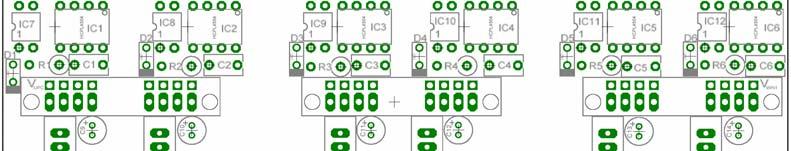


6 Figure 5: BP6A PCB Layout Component Legend Component Side Solder Side 6
VLA Hybrid Gate Driver Application Information. DC-DC Converter V D 15V. V iso = 2500V RMS
 Application NOTES: Last Revision November 15, 2004 VLA500-01 Hybrid Gate Driver Application Information Contents: 1. General Description 2. Short Circuit Protection 2.1 Destaruation Detection 2.2 VLA500-01
L-Series Power Devices
 L-Series Power Devices Application Note Table of Contents Application Information 1.0 Introduction...1 1.1 L-Series Intelligent Power Modules...1 1.2 L-Series High Power IPMs...1 1.3 L-Series Numbering
Hybrid ICs Drive High-Power IGBT Modules
 Hybrid ICs Drive High-Power IGBT Modules A pair of hybrid gate-driver ICs use optocoupling and isolated power supplies in compact, single inline packages to simplify the design of drive circuits for high-power
M57161L-01 Gate Driver
 Gate Driver Block Diagram V D 15V V IN 5V - 1 2 3 4 5 6-390Ω DC-DC Converter V iso= 2500V RMS Optocoupler Dimensions Inches Millimeters A 3.27 Max. 83.0 Max. B 1.18 Max. 30.0 Max. C 0.59 Max. 15.0 Max.
RAPID DESIGN KITS FOR THREE PHASE MOTOR DRIVES. Nicholas Clark Applications Engineer Powerex, Inc.
 by Nicholas Clark Applications Engineer Powerex, Inc. Abstract: This paper presents methods for quick prototyping of motor drive designs. The techniques shown can be used for a wide power range and demonstrate
N 36 NU 37 W 38 V 39 U 40 P 41 U 42 V
 Powerex, Inc., 173 Pavilion Lane, Youngwood, Pennsylvania 15697 (724) 925-7272 Dual-In-Line Intelligent Power Module J K Q V 1 2 3 4 5 6 7 8 9 10 11 12 13 14 15 16 1718 19 29 41 42 B M (2 PLACES) L (5
VLA500K-01R. Hybrid IC IGBT Gate Driver + DC/DC Converter
 Powerex, Inc., 200. Hillis Street, Youngwood, Pennsylvania 15697-1800 (724) 925-7272 Hybrid IC IGBT Gate Driver + A C B D V D G i V l + V l 1 30 1 2 3 4 6 7 DC-AC CONVRTR 180Ω OPTO COUPLR Outline Drawing
Application Manual for QP12W05S-37 Hybrid Gate Driver
 Application Manual for QP12W5S-7 Hybrid Gate Driver Description The QP12W5S-7 is a hybrid integrated circuit designed to provide gate drive for high power IGBT modules. The output characteristics are compatible
C L DETAIL "B" TERMINAL CODE 1 (VNC) 2 VUFB 3 VVFB 4 VWFB 5 UP 6 VP 7 WP 8 VP1 9 VNC* 10 UN 11 VN 12 WN 13 VN1 HEATSINK SIDE
 2 VUFB 3 VVFB 4 VWFB 5 UP 6 VP 7 WP 8 VP1 9 VNC* 10 UN 11 VN 12 WN 13 VN1 HEATSINK SIDE") Dual In-line Intelligent Power Module R S A N D P X K C L AG U P 17 18 16 19 HEATSINK SIDE Y 15 R 14 20 13 12 11 21 10 9 Outline Drawing and Circuit Diagram 8 Dimensions Inches Millimeters A 1.50±0.02
Dual In-line Intelligent Power Module R S A N D P X K C L AG U P 17 18 16 19 HEATSINK SIDE Y 15 R 14 20 13 12 11 21 10 9 Outline Drawing and Circuit Diagram 8 Dimensions Inches Millimeters A 1.50±0.02
Figure 1.1 Fully Isolated Gate Driver
 Release Date: 3-4-09 1.0 Driving IGBT Modules When using high power IGBT modules, it is often desirable to completely isolate control circuits from the gate drive. A block diagram of this type of gate
New Power Stage Building Blocks for Small Motor Drives
 New Power Stage Building Blocks for Small Motor s Eric R. Motto*, John F. Donlon*, H. Iwamoto** * Powerex Inc., Youngwood, Pennsylvania, USA ** Mitsubishi Electric, Power Device Division, Fukuoka, Japan
Mitsubishi Semiconductors <Dual-In-Line Package Intelligent Power Module> PS21865 Transfer-Mold Type Insulated Type
 Pre DS.Kou,M.Sakai,F.Tametani Rev D D S.Kou,T.Iwagami,F.Tametani Apr DM.Fukunaga 02-8/9 M.Fukunaga 03-8/6 Applications : AC100V 200V three-phase inverter drive for small power motor control. Integrated
VLA567-01R. Hybrid IC IGBT Gate Driver + DC/DC Converter
 VLA57-R Powerex, Inc., 73 Pavilion Lane, Youngwood, Pennsylvania 597 (7) 95-77 www.pwrx.com Hybrid IC IGBT Gate Driver + DC/DC Converter A 3 B D Description: VLA57-R is a hybrid integrated circuit designed
PS21867-P. Intellimod Module Dual-In-Line Intelligent Power Module 30 Amperes/600 Volts
 Powerex, Inc., 200 E. Hillis Street, Youngwood, Pennsylvania 15697-1800 (724) 925-7272 Dual-In-Line Intelligent Power Module J A N M C BB P B AA 27 28 30 31 33 35 21 1 2 3 4 29 5 6 7 8 32 9 1 12 13 34
PS21265-P PS21265-AP Intellimod Module Dual-In-Line Intelligent Power Module 20 Amperes/600 Volts
 PS21265-P PS21265-AP Dual-In-Line Intelligent Power Module H A DETAIL "A" HEATSINK SIDE 1 2 3 4 5 6 7 8 9 10 11 12 13 14 15 16 17 18 19 20 21 M B K P N J 22 23 24 25 26 C L Q DETAIL "A" W G DETAIL "C"
Application Note Mitsubishi Semiconductors <Dual-In-Line Package Intelligent Power Module> PS21867 Transfer-Mold Type Insulated Type
 Application Note Mitsubishi Semiconductors Insulated Type Pre. T.Iwagami Rev. F S.Kou, T.Iwagami, F.Tametani Apr. M.Iwasaki 01-12/21 M.Fukunaga 03-8/6 Applications
AB (2 PLACES) 30 NC 31 P 33 V 34 W
 30 NC 31 P 33 V 34 W") Dual-In-Line Intelligent Power Module A D G H R DUMMY PINS J K L Q C HEATSINK SIDE B 28 27 26 25 24 23 22 21 20 19 18 17 16 15 14 13 12 11 10 29 30 E E E F 9 8 F 7 6 5 4 3 2 1 M P 35 35 34 33 32 31 N P
Dual-In-Line Intelligent Power Module A D G H R DUMMY PINS J K L Q C HEATSINK SIDE B 28 27 26 25 24 23 22 21 20 19 18 17 16 15 14 13 12 11 10 29 30 E E E F 9 8 F 7 6 5 4 3 2 1 M P 35 35 34 33 32 31 N P
PS S Intellimod Module Dual-In-Line Intelligent Power Module 20 Amperes/600 Volts
 Dual-In-Line Intelligent Power Module R O A D N P X K C L AF R P 17 16 15 14 13 12 11 10 9 8 7 6 5 4 3 2 1 18 19 20 U HEATSINK SIDE Outline Drawing and Circuit Diagram Dimensions Inches Millimeters A 1.50±0.02
6.0.2 V-Series High Power IPMs. The V-Series IPM was developed in order to address newly emerging. Table 6.1 Powerex Intelligent Power Modules
 6. Introduction to Intellimod Intelligent Power Modules Powerex Intellimod Intelligent Power Modules (IPMs) are advanced hybrid power devices that combine high speed, low loss IGBTs with optimized gate
N P HEATSINK SIDE 25 UN 26 VUFB 27 UP 30 NC 31 NC 32 NC 33 NC 34 NC 35 NC 28 U(VUFS) 29 NC
 29 NC") Single-In-Line Intelligent Power Module A D G H J K L M N P C W X E 35 34 33 32 31 30 Y V (2 PLACES) F PS21661-RZ AA AK AJ Z B 1 3 2 5 4 7 6 9 8 11 3 12 15 14 17 16 19 18 21 25 26 27 28 20 22 23 24 29
Single-In-Line Intelligent Power Module A D G H J K L M N P C W X E 35 34 33 32 31 30 Y V (2 PLACES) F PS21661-RZ AA AK AJ Z B 1 3 2 5 4 7 6 9 8 11 3 12 15 14 17 16 19 18 21 25 26 27 28 20 22 23 24 29
Chapter 4. Typical application circuits
 Chapter 4 Typical application circuits Table of Contents age 1 Typical application circuits... 4-2 2 Important points... 4-6 3 Optocoupler peripheral circuits... 4-9 4 Connector... 4-11 4-1 1 Typical application
PP400B060-ND. H-Bridge POW-R-PAK IGBT Assembly 400 Amperes/600 Volts
 Powerex, Inc., 173 Pavilion Lane, Youngwood, Pennsylvania 15697 (724) 925-7272 www.pwrx.com H-Bridge POW-R-PAK IGBT Assembly Q Q J P (8 PLACES) +DC C2E1 R (2 PLACES) PIN 1 N U B M N F DC L (6 PLACES) G
Y Y D T SQ PIN (10 PLS) L N TERMINAL CODE 5 : FNO 4 : VNC N 3 : CN1 2 : NC 1 : VN1 5 : FPO 4 : VPC P 3 : CP1 2 : NC 1 : VP1. FWDi IGBT C2E1.
 L N TERMINAL CODE 5 : FNO 4 : VNC N 3 : CN1 2 : NC 1 : VN1 5 : FPO 4 : VPC P 3 : CP1 2 : NC 1 : VP1. FWDi IGBT C2E1.") PM8DV1B6 Powerex, Inc., 173 Pavilion Lane, oungwood, Pennsylvania 1697 (724) 92-7272 www.pwrx.com Single Phase IGBT Inverter Output 8 Amperes/6 Volts F (4 PLACES) A C U V B E H (3 TP) C2E1 E2 C1 4 3 2
PM8DV1B6 Powerex, Inc., 173 Pavilion Lane, oungwood, Pennsylvania 1697 (724) 92-7272 www.pwrx.com Single Phase IGBT Inverter Output 8 Amperes/6 Volts F (4 PLACES) A C U V B E H (3 TP) C2E1 E2 C1 4 3 2
PS , PS A, PS C Intellimod Module Dual-In-Line Intelligent Power Module 20 Amperes/600 Volts
 PS21965-4, PS21965-4A, PS21965-4C Dual-In-Line Intelligent Power Module R A D N O P 17 16 15 14 13 12 11 10 9 8 7 6 5 4 3 2 1 PS21965-4C DETAIL "A" X K K V G F E H C J L DETAIL "B" AD AE PS21965-4 / PS21965-4A
PS21963-S Intellimod Module Dual-In-Line Intelligent Power Module 10 Amperes/600 Volts
 Dual-In-Line Intelligent Power Module R O A D N P X K C L FF R U 17 16 15 14 13 12 11 10 9 8 7 6 5 4 3 2 1 18 19 20 HEATSINK SIDE Outline Drawing and Circuit Diagram 21 Dimensions Inches Millimeters A
VLA Hybrid IC IGBT Gate Driver + DC/DC Converter
 VLA52-1 Powerex, Inc., 2 E. Hillis Street, Youngwood, Pennsylvania 1597-1 (72) 925-7272 Hybrid IC IGBT Gate Driver + A C B D V D 15V 1 3 + + CONTROL INPUT 5V 1 2 3 7 E 3Ω DC-DC CONVERTER V iso = 25V RMS
PS , PS A, PS C Intellimod Module Dual-In-Line Intelligent Power Module 5 Amperes/600 Volts
 PS21962-4, PS21962-4A, PS21962-4C Dual-In-Line Intelligent Power Module R A D N O P 17 16 15 14 13 12 11 10 9 8 7 6 5 4 3 2 1 PS21962-4C DETAIL "A" X K K V G F E H C J L DETAIL "B" AD AE PS21962-4 / PS21962-4A
Smart Pack Electric Co., Ltd <Intelligent Power Module> SPE10S60F-A TRANSFER-MOLD TYPE FULL PACK TYPE
 INTEGRATED POWER FUNCTIONS 600V/10A low-loss 6th generation IGBT inverter bridge for three phase DC-to-AC power conversion. Open emitter type. Figure 1 INTEGRATED DRIVE, PROTECTION AND SYSTEM CONTROL FUNCTIONS
Schematic V F HCPL-7601/11 SHIELD. USE OF A 0.1 µf BYPASS CAPACITOR CONNECTED BETWEEN PINS 5 AND 8 IS REQUIRED (SEE NOTE 1).
.") CMOS/TTL Compatible, Low Input Current, High Speed, High CMR Optocoupler Technical Data HCPL-7601 HCPL-7611 Features Low Input Current Version of HCPL-2601/11 and 6N137 Wide Input Current Range: I F =
CMOS/TTL Compatible, Low Input Current, High Speed, High CMR Optocoupler Technical Data HCPL-7601 HCPL-7611 Features Low Input Current Version of HCPL-2601/11 and 6N137 Wide Input Current Range: I F =
PS21661-RZ/FR PS21661-FR. APPLICATION AC100V~200V, three-phase inverter drive for small power motor control.
 MITSUBISHI SEMICONDUCTOR TYPE TYPE PS21661-RZ PS21661-FR INTEGRATED POWER FUNCTIONS 600/3A low-loss 5th generation IGBT inverter bridge for 3 phase
PS21562-SP PS21562-SP. APPLICATION AC100V~200V inverter drive for small power motor control. PS21562-SP
 MITSUBISHI SEMICONDUCTOR TYPE TYPE INTEGRATED POWER FUNCTIONS 600/5A low-loss 5 th generation IGBT inverter bridge for three phase DC-to-AC power conversion.
Smart Pack Electric Co., Ltd <Intelligent Power Module> SPE05M50F-A TRANSFER-MOLD TYPE FULL PACK TYPE
 Control Part Applications 500V/5A low-loss MOSFET inverter driver for Small Power AC Motor Drives Figure 1 Features 500V Rds(on)=1.8Ohm(Max)MOSFET 3-Phase inverter with Gate Drivers and protection Separate
PS21562-P. Intellimod Module Dual-In-Line Intelligent Power Module 5 Amperes/600 Volts
 Dual-In-Line Intelligent Power Module A D DUMMY PINS K H L Q R C B 28 27 29 30 26 25 24 23 22 21 20 19 18 17 16 15 14 13 LABEL E E E F 12 11 10 9 8 F 7 6 5 4 3 2 1 M C L P 35 HEATSINK SIDE 35 34 33 32
PS21A79 MAIN FUNCTION AND RATINGS 3 phase inverter with N-side open emitter structure 600V / 50A (CSTBT)
") MAIN FUNCTION AND RATINGS 3 phase inverter with N-side open emitter structure 600V / 50A (CSTBT) APPLICATION AC100 ~ 200Vrms class, motor control INTEGRATED DRIVE, PROTECTION AND SYSTEM CONTROL FUNCTIONS
MAIN FUNCTION AND RATINGS 3 phase inverter with N-side open emitter structure 600V / 50A (CSTBT) APPLICATION AC100 ~ 200Vrms class, motor control INTEGRATED DRIVE, PROTECTION AND SYSTEM CONTROL FUNCTIONS
PM75CL1A120 FLAT-BASE TYPE INSULATED PACKAGE
 PMCL1A1 PMCL1A1 FEATURE verter + Drive & Protection IC a) Adopting new th generation Full-Gate CSTBT TM chip b) The over-temperature protection which detects the chip surface temperature of CSTBT TM is
TENTATIVE PP800D120-V01
 Description: The Powerex POW-R-PAK is a configurable IGBT based power assembly that may be used as a converter, chopper, half or full bridge, or three phase inverter for motor control, power supply, UPS
VLA554-01R. IGBT Gate Driver + DC/DC Converter
 VLA55-R Powerex, Inc., 7 Pavilion Lane, Youngwood, Pennsylvania 597 (7) 95-77 www.pwrx.com IGBT Gate Driver + DC/DC Converter A C B J K D E H D F V D G i V+ IN 5 V EE Circuit Diagram Dimensions Inches
TENTATIVE PP225D120. POW-R-PAK TM 225A / 1200V Half Bridge IGBT Assembly. Description:
 Description: The Powerex is a configurable IGBT based power assembly that may be used as a converter, chopper, half or full bridge, or three phase inverter for motor control, power supply, UPS or other
T - 4 TYP. XØ (2 PLACES) W SQ. PIN (10 PLACES) TERMINAL CODE 1. VN1 2. SNR 3. CN1 4. VNC 5. FNO VP1 RFO AMP E2 C2E1 C1
 W SQ. PIN (10 PLACES) TERMINAL CODE 1. VN1 2. SNR 3. CN1 4. VNC 5. FNO VP1 RFO AMP E2 C2E1 C1") PM2DVA12 Powerex, Inc., 2 Hillis Street, Youngwood, Pennsylvania 15697-18 (724) 925-7272 Single Phase IGBT Inverter Output 2 Amperes/12 Volts A D T - 4 TYP. XØ (2 PLACES) B E F J H R S NUTS - 3 TYP. U
PM2DVA12 Powerex, Inc., 2 Hillis Street, Youngwood, Pennsylvania 15697-18 (724) 925-7272 Single Phase IGBT Inverter Output 2 Amperes/12 Volts A D T - 4 TYP. XØ (2 PLACES) B E F J H R S NUTS - 3 TYP. U
APPLICATION AC100V~200V three-phase inverter drive for small power motor control (1.96) 17.7 (3.5) 35.9 ±0.5 (5.5)
 17.7 (3.5) 35.9 ±0.5 (5.5)") MITSUBISHI SEMICONDUCTOR TYPE TYPE INTEGRATED POWER FCTIONS 600/30A low-loss CSTBT TM inverter bridge with N-side three-phase output DC-to-AC power
MITSUBISHI SEMICONDUCTOR TYPE TYPE INTEGRATED POWER FCTIONS 600/30A low-loss CSTBT TM inverter bridge with N-side three-phase output DC-to-AC power
PM50CLA120. APPLICATION General purpose inverter, servo drives and other motor controls PM50CLA120 FEATURE MITSUBISHI <INTELLIGENT POWER MODULES>
 FEATURE a) Adopting new th generation IGBT (CSTBT) chip, which performance is improved by 1µm fine rule process. r example, typical ce(sat)=1.9 @Tj=1 C b) I adopt the over-temperature conservation by Tj
BAP1551 Gate Drive Board
 Application Note and Datasheet for Half Bridge Inverters Figure 1: BAP1551 IGBT Gate Driver Board Patent Pending Introduction The BAP1551 Insulated Gate Bipolar Transistor (IGBT) Gate Drive Board (GDB)
VLA541-01R. IGBT Gate Driver
 VLA-R Powerex, Inc., 73 Pavilion Lane, Youngwood, Pennsylvania 97 (7) 9-77 www.pwrx.com Circuit Diagram V l V l - 3 Dimensions Inches Millimeters A.73 Max.. Max. B. Max.. Max. C.3 Max.. Max. D. Max.. Max.
EUP V/12V Synchronous Buck PWM Controller DESCRIPTION FEATURES APPLICATIONS. Typical Application Circuit. 1
 5V/12V Synchronous Buck PWM Controller DESCRIPTION The is a high efficiency, fixed 300kHz frequency, voltage mode, synchronous PWM controller. The device drives two low cost N-channel MOSFETs and is designed
PS , PS A, PS C Intellimod Module Dual-In-Line Intelligent Power Module 3 Amperes/600 Volts
 PS21961-4, PS21961-4A, Dual-In-Line Intelligent Power Module R A D N O P 17 16 15 14 13 12 11 10 9 8 7 6 5 4 3 2 1 DTAIL "A" X K K V G F H C J L DTAIL "B" AD A PS21961-4 / PS21961-4A AD A R O A N D P X
PS21767 Intellimod Module Dual-In-Line Intelligent Power Module 30 Amperes/600 Volts
 ual-in-line Intelligent Power Module B Z H AE AF AJ AK Z AH T E AA AB G F F F F F 28 27 26 25 24 23 22 21 20 19 1817 16 15 14 13 12 1110 9 8 7 6 5 4 3 2 1 31 29 30 32 33 ETAIL "" AB C A ETAIL "A" ETAIL
Technical. Application. Assembly. Availability. Pricing. Phone
 6121 Baker Road, Suite 108 Minnetonka, MN 55345 www.chtechnology.com Phone (952) 933-6190 Fax (952) 933-6223 1-800-274-4284 Thank you for downloading this document from C&H Technology, Inc. Please contact
NJM3777 DUAL STEPPER MOTOR DRIVER NJM3777E3(SOP24)
") DUAL STEPPER MOTOR DRIER GENERAL DESCRIPTION The NJM3777 is a switch-mode (chopper), constant-current driver with two channels: one for each winding of a two-phase stepper motor. The NJM3777 is equipped
DUAL STEPPER MOTOR DRIER GENERAL DESCRIPTION The NJM3777 is a switch-mode (chopper), constant-current driver with two channels: one for each winding of a two-phase stepper motor. The NJM3777 is equipped
Chapter 1. Product Outline
 Chapter 1 Product Outline Contents Page 1. Introduction... 1-2 2. Product line-up... 1-4 3. Definition of type name and marking spec... 1-5 4. Package outline dimensions... 1-6 5. Absolute maximum ratings...
LM2462 Monolithic Triple 3 ns CRT Driver
 LM2462 Monolithic Triple 3 ns CRT Driver General Description The LM2462 is an integrated high voltage CRT driver circuit designed for use in color monitor applications. The IC contains three high input
LDIP- IPM IM (Preliminary)
") LDIP- IPM (Preliminary) Description Cyntec IPM is integrated Drive, protection and system control functions that is designed for high performance 3-phase motor driver application like: Home appliances
LDIP- IPM (Preliminary) Description Cyntec IPM is integrated Drive, protection and system control functions that is designed for high performance 3-phase motor driver application like: Home appliances
SLIMDIP-L TRANSFER MOLDING TYPE INSULATED TYPE
 OUTLINE MAIN FUNCTION AND RATINGS RC-IGBT inverter bridge for three phase DC-to-AC power conversion Built-in bootstrap diodes with current limiting resistor Open emitter type APPLICATION AC 100~240V (DC
AC/DC to Logic Interface Optocouplers Technical Data
 H AC/DC to Logic Interface Optocouplers Technical Data HCPL-37 HCPL-376 Features Standard (HCPL-37) and Low Input Current (HCPL-376) Versions AC or DC Input Programmable Sense Voltage Hysteresis Logic
< Dual-In-Line Package Intelligent Power Module > PSS25SA2FT TRANSFER MOLDING TYPE INSULATED TYPE
 OUTLINE MAIN FEATURES AND RATINGS 3 phase DC/AC inverter 1200V / 25A Built-in LPT-CSTBT (6th generation IGBT) Built-in bootstrap diodes with current limiting resistor Insulated transfer molding package
LBI-38858A. Mobile Communications SERIAL PROGRAMMING KIT TQ3370. Maintenance Manual 1
 LBI-38858A Mobile Communications SERIAL PROGRAMMING KIT TQ3370 Maintenance Manual 1 TABLE OF CONTENTS DESCRIPTION.............................. 1 OUTLINE DIAGRAMS TQ3370 Assembly............................
Dimensions in mm Max Max. 4.5 Max. 5.5 Max. 7.5 Max. 4 VCC. S/C Detect Off Time Adjustor. Detect. Circuit. VG Monitor 5 VO.
 M7AL- Powerex, Inc., Hillis Street, Youngwood, Pennsylvania 97- (7) 9-77 Gate Driver Outline Drawing 9. Max. Block Diagram Signal Input 3 Opto-Coupler 7. Max.. 3 = 33. Interface Latch Timer & Reset Circuit
PM25CLA120. APPLICATION General purpose inverter, servo drives and other motor controls PM25CLA120 MITSUBISHI <INTELLIGENT POWER MODULES>
 FETURE a) dopting new 5th generation (CSTBT) chip, which performance is improved by 1µm fine rule process. r example, typical ce(sat)=1.9 @Tj=125 b) I adopt the over-temperature conservation by Tj detection
U P V VPI VFO WFO UP UFO V VPC GND GND
 N A C D Q Q Q 1 234 5678 9 11 13 15 17 2 14 16 18 V (14 TYP.) R (2 TYP.) 1. VUPC 2. UFO 3. UP 4. VUPI 5. VVPC 6. VFO 7. VP 8. VVPI 9. VWPC 10. WFO 11. WP 12. VWPI 13. 14. 15. 16. 17. 18. 19. 20. 21. 22.
U P V VPI VFO R (2 TYP.) WFO UP UFO V VPC GND GND
 WFO UP UFO V VPC GND GND") N A C D Q Q Q 1 234 5678 9 11 13 15 17 2 14 16 18 V (14 TYP.) R (2 TYP.) 1. VUPC 2. UFO 3. UP 4. VUPI 5. VVPC 6. VFO 7. VP 8. VVPI 9. VWPC 10. WFO 11. WP 12. VWPI 13. 14. 15. 16. 17. 18. 19. 20. 21. 22.
N A C D Q Q Q 1 234 5678 9 11 13 15 17 2 14 16 18 V (14 TYP.) R (2 TYP.) 1. VUPC 2. UFO 3. UP 4. VUPI 5. VVPC 6. VFO 7. VP 8. VVPI 9. VWPC 10. WFO 11. WP 12. VWPI 13. 14. 15. 16. 17. 18. 19. 20. 21. 22.
Application Note 1047
 Low On-Resistance Solid-State Relays for High-Reliability Applications Application Note 10 Introduction In military, aerospace, and commercial applications, the high performance, long lifetime, and immunity
PSS25NC1FT TRANSFER MOLDING TYPE INSULATED TYPE
 OUTLINE MAIN FUNCTION CI(Converter + Inverter) type IPM 3-phase Inverter 3-phase Converter RATING Inverter part : 25A/1200V (CSTBT) APPLICATION AC400V three phase motor inverter drive * With brake circuit
PSS15MC1FT TRANSFER MOLDING TYPE INSULATED TYPE
 OUTLINE MAIN FUNCTION CIB(Converter Inverter Brake) type IPM 3-phase Inverter Brake circuit 3-phase Converter RATING Inverter part : 15A/1200V (CSTBT) APPLICATION AC400V three phase motor inverter drive
APPLICATION AC100V~200V three-phase inverter drive for small power motor control (1.96) 17.7 (12.78) (3.5) 35.9 ±0.5 (5.5) (13.5)
 17.7 (12.78) (3.5) 35.9 ±0.5 (5.5) (13.5)") MITSUBISHI SEMICONDUCTOR TEGRATED POWER FUNCTIONS TYPE TYPE 600/30A low-loss CSTBT TM inverter bridge with N-side three-phase output DC-to-AC power
MITSUBISHI SEMICONDUCTOR TEGRATED POWER FUNCTIONS TYPE TYPE 600/30A low-loss CSTBT TM inverter bridge with N-side three-phase output DC-to-AC power
IS31LT3954_IS32LT3954 DEMO BOARD GUIDE
 DESCRIPTION The IS31LT3954_IS32LT3954 is a DC-to-DC switching converter, which integrate an N-channel MOSFET to operate in a buck configuration. The device supply a wide input voltage between 4.5V and
User s Manual. ACPL-339J Isolated Gate Driver Evaluation Board. Quick-Start. Testing Either Arm of The Half Bridge Inverter Driver (without IGBT)
") ACPL-339J Isolated Gate Driver Evaluation Board User s Manual Quick-Start Visual inspection is needed to ensure that the evaluation board is received in good condition. The default connections of the evaluation
ACPL-339J Isolated Gate Driver Evaluation Board User s Manual Quick-Start Visual inspection is needed to ensure that the evaluation board is received in good condition. The default connections of the evaluation
PM30CSJ060 Intellimod Module Three Phase IGBT Inverter Output 30 Amperes/600 Volts
 Three Phase IGBT Inverter Output N A C D Q Q Q 1 234 5678 9 11 13 15 17 2 14 16 18 V (14 TYP.) R (2 TYP.) 1. VUPC 2. UFO 3. UP 4. VUPI 5. VVPC 6. VFO 7. VP 8. VVPI 9. VWPC 1. WFO 11. WP 12. VWPI 13. 14.
Designated client product
 Designated client product This product will be discontinued its production in the near term. And it is provided for customers currently in use only, with a time limit. It can not be available for your
Discrete Op-Amp Kit MitchElectronics 2019
 Discrete Op-Amp Kit MitchElectronics 2019 www.mitchelectronics.co.uk CONTENTS Introduction 3 Schematic 4 How It Works 5 Materials 9 Construction 10 Important Information 11 Page 2 INTRODUCTION Even if
Dual Channel, High Speed Optocouplers Technical Data
 Dual Channel, High Speed Optocouplers Technical Data HCPL-5 HCPL-5 HCPL-454 HCPL-5 HCPL-5 HCPL-54 Features 5 kv/µs Minimum Common Mode Transient Immunity at V CM = 5 V (HCPL-454/54) High Speed: Mb/s TTL
PS11035 Intellimod Module Application Specific IPM 20 Amperes/600 Volts
 F A D E G U W X C 2 1 3 5 4 6 7 8 10 14 9 11 12 13 15 16 (S) B J K L M AA BB S T V 21 22 23 24 25 26 27 28 29 30 FF 1 CBU+ 2 CBU- 3 CBV+ 4 CBV- 5 CBW+ 6 CBW- 7 VD 8 UP Outline Drawing and Circuit Diagram
V VPI V (14 TYP.) VFO R (2 TYP.) WFO UP UFO V VPC GND GND GND GND GND GND VCC
 VFO R (2 TYP.) WFO UP UFO V VPC GND GND GND GND GND GND VCC") Powerex, Inc., 200 Hillis Street, Youngwood, Pennsylvania 15697-1800 (724) 925-7272 Three Phase IGBT Inverter Output N A C D Q Q Q 1 234 5678 9 11 13 15 17 2 14 16 18 V (14 TYP.) R (2 TYP.) 1. VUPC 2.
Powerex, Inc., 200 Hillis Street, Youngwood, Pennsylvania 15697-1800 (724) 925-7272 Three Phase IGBT Inverter Output N A C D Q Q Q 1 234 5678 9 11 13 15 17 2 14 16 18 V (14 TYP.) R (2 TYP.) 1. VUPC 2.
PM150RLB060. APPLICATION General purpose inverter, servo drives and other motor controls PM150RLB060.
 FLT-BSE TYPE INSULTED PCKGE FETURE a) dopting new 5th generation (CSTBT) chip, which performance is improved by µm fine rule process. r example, typical ce(sat)= @Tj=25 b) I adopt the over-temperature
IAP200T120 SixPac 200A / 1200V 3-Phase Bridge IGBT Inverter
 Configurable Power FEATURES INCLUDE Multi-Function Power Assembly Compact Size 9 H X 17.60 W X 11.00 D DC Bus Voltages to 850VDC Snubber-less operation to 650VDC Switching frequencies to over 20kHz Protective
MAX13487E Evaluation Kit. Evaluates: MAX13487E/MAX13488E. Features
 9-0; Rev ; /08 General Description The MAX87E evaluation kit (EV kit) is a fully assembled and tested PCB that contains a half-duplex RS- 85/RS- AutoDirection-controlled transceiver with ESD protection.
U (2 TYP.) T WFO VUPC IN F O GND GND OUT OT OUT OT S I
 T WFO VUPC IN F O GND GND OUT OT OUT OT S I") Powerex, Inc., 200 E. Hillis Street, Youngwood, Pennsylvania 15697-1800 (724) 925-7272 Three Phase IGBT Inverter W (6 PLACES) X (4 PLACES) AD AA W A B K K L Z V Z U AG Z AB AE AG B N P AC AC AH M M AF
Powerex, Inc., 200 E. Hillis Street, Youngwood, Pennsylvania 15697-1800 (724) 925-7272 Three Phase IGBT Inverter W (6 PLACES) X (4 PLACES) AD AA W A B K K L Z V Z U AG Z AB AE AG B N P AC AC AH M M AF
HMC3716LP4E FREQUENCY DIVIDERS AND DETECTORS - SMT. Typical Applications. General Description. Functional Diagram
 Typical Applications The HMC3716LPE is ideal for: Point-to-Point Radios Satellite Communication Systems Military Applications Sonet Clock Generation General Description Functional Diagram Features Ultra
Dual Channel, High Speed Optocouplers Technical Data
 Dual Channel, High Speed Optocouplers Technical Data HCPL-2530 HCPL-2531 HCPL-4534 HCPL-0530 HCPL-0531 HCPL-0534 Features 15 kv/µs Minimum Common Mode Transient Immunity at V CM = 1500 V (HCPL-4534/0534)
SUPPLIER PHONE FAX WEBSITE TDK Maxim Integrated Products 1
 19-2574; Rev 0; 9/02 MAX4001 Evaluation Kit General Description The MAX4001 evaluation kit (EV kit) is a fully assembled and tested surface-mount circuit board that evaluates the MAX4001 RF-detecting controller
DUAL STEPPER MOTOR DRIVER
 DUAL STEPPER MOTOR DRIVER GENERAL DESCRIPTION The is a switch-mode (chopper), constant-current driver with two channels: one for each winding of a two-phase stepper motor. is equipped with a Disable input
PS11036 Intellimod Module Application Specific IPM 30 Amperes/600 Volts
 1 2 3 4 5 6 7 8 9 10 11 12 13 14 15 16 A D G H G J K M L GG EE (4 PLACES) BB N P 12 3 4 5 6 7 8 9 10 111213 14 1516 T S Q R U 21 22 23 24 25 26 27 28 29 W V X Z LABEL Outline Drawing and Circuit Diagram
Detail of Signal Input/Output Terminals
 Contents Page 1. Control Power Supply Terminals VCCH,VCCL,COM... 3-2 2. Power Supply Terminals of High Side VB(U,V,W)... 3-6 3. Function of Internal BSDs (Boot Strap Diodes)... 3-9 4. Input Terminals IN(HU,HV,HW),
SLLIMM -nano small low-loss intelligent molded module IPM, 3 A, 600 V, 3-phase IGBT inverter bridge. Description. Table 1: Device summary
 SLLIMM -nano small low-loss intelligent molded module IPM, 3 A, 600 V, 3-phase IGBT inverter bridge Datasheet - production data Features IPM 3 A, 600 V, 3-phase IGBT inverter bridge including control ICs
LVDS Flow Through Evaluation Boards. LVDS47/48EVK Revision 1.0
 LVDS Flow Through Evaluation Boards LVDS47/48EVK Revision 1.0 January 2000 6.0.0 LVDS Flow Through Evaluation Boards 6.1.0 The Flow Through LVDS Evaluation Board The Flow Through LVDS Evaluation Board
LM2412 Monolithic Triple 2.8 ns CRT Driver
 Monolithic Triple 2.8 ns CRT Driver General Description The is an integrated high voltage CRT driver circuit designed for use in high resolution color monitor applications. The IC contains three high input
NJM37717 STEPPER MOTOR DRIVER
 STEPPER MOTOR DRIVER GENERAL DESCRIPTION PACKAGE OUTLINE NJM37717 is a stepper motor diver, which consists of a LS-TTL compatible logic input stage, a current sensor, a monostable multivibrator and a high
IS31LT3953_IS32LT3953 DEMO BOARD GUIDE
 DESCRIPTION The IS31LT3953_IS32LT3953 is a DC-to-DC switching converter, which integrate an N-channel MOSFET to operate in a buck configuration. The device supply a wide input voltage between 4.5V and
AN4781 Application note
 Application note STEVAL-IFP028V1 evaluation board for single high-side driver IPS160H Introduction The STEVAL-IFP028V1 is an evaluation board designed to analyze all IPS160H functionality. It is designed
NJM3773 DUAL STEPPER MOTOR DRIVER
 NJ77 DUAL STEPPE OTO DIE GENEAL DESCIPTION The NJ77 is a switch-mode (chopper), constant-current driver with two channels: one for each winding of a two-phase stepper motor. The NJ77 is also equipped with
VLA546-01R. IGBT Gate Driver
 VLA-R Powerex, Inc., 73 Pavilion Lane, Youngwood, Pennsylvania 97 (7) 9-77 www.pwrx.com Circuit Diagram V l V l - 3 E F D D Ω OPTO COUPLER Dimensions Inches Millimeters A.73 Max.. Max. B. Max.. Max. C.33
Features: Phase A Phase B Phase C -DC_A -DC_B -DC_C
 Three Phase Inverter Power Stage Description: The SixPac TM from Applied Power Systems is a configurable IGBT based power stage that is configured as a three-phase bridge inverter for motor control, power
MIC4421/4422. Bipolar/CMOS/DMOS Process. General Description. Features. Applications. Functional Diagram. 9A-Peak Low-Side MOSFET Driver
 9A-Peak Low-Side MOSFET Driver Micrel Bipolar/CMOS/DMOS Process General Description MIC4421 and MIC4422 MOSFET drivers are rugged, efficient, and easy to use. The MIC4421 is an inverting driver, while
Application Note CDIAN003
 Application Note CDIAN003 CDI GaN Bias Board User s Guide Revision 4.0 February 20, 2015 Quick Start Guide Shown below are the essential connections, controls, and indicators for the GaN Bias Control Board.
VLA Hybrid IC IGBT Gate Driver
 Powerex, Inc., 73 Pavilion Lane, Youngwood, Pennsylvania 697-8 (7) 9-77 Hybrid I IBT ate Driver A B K 3 8Ω D Outline Drawing and ircuit Diagram Dimensions Inches Millimeters A.. B. 6... D... 3. F.3 7..
VLA Hybrid IC IGBT Gate Driver
 Powerex, Inc., 173 Pavilion Lane, Youngwood, Pennsylvania 15697-18 (724) 925-7272 Hybrid I IBT ate Driver A B K D J H D F 14 14 1 INTRFA LATH TIMR AND RST IRUIT DTT IRUIT 4 2 1 5 V ONTROL PIN FOR t trip
HCPL-576x* AC/DC to Logic Interface Hermetically Sealed Optocouplers
 HCPL-576x* 5962-8947701 AC/DC to Logic Interface Hermetically Sealed Optocouplers Data Sheet Description These devices are single channel, hermetically sealed, voltage/current threshold detection optocouplers.
SLLIMM small low-loss intelligent molded module IPM, 3-phase inverter - 15 A, 600 V short-circuit rugged IGBT. Description. Table 1.
 SLLIMM small low-loss intelligent molded module IPM, 3-phase inverter - 15 A, 600 V short-circuit rugged IGBT Applications Datasheet - production data 3-phase inverters for motor drives Home appliance,
Hardware Guide. Control Made Simple. Model 401A Signal Generator
 Control Made Simple Model 401A Signal Generator Hardware Guide ON OFF LIMIT 1 2 3 4 RXD TXD POWER West Coast Office 1263 El Camino Real Menlo Park, CA 94025 Phone (650) 853-1444 Fax (650) 853-1405 www.flashcutcnc.com
6N135, 6N136 Single Channel, High Speed Optocouplers
 6N135, 6N136 Single Channel, High Speed Optocouplers Jan.2009 Description The 6N135/6 consists of a high efficient AlGaAs Light Emitting Diode and a high speed optical detector. This design provides excellent
PM300DSA060 Intellimod Module Single Phase IGBT Inverter Output 300 Amperes/600 Volts
 Powerex, Inc., 2 Hillis Street, Youngwood, Pennsylvania 15697-18 (724) 925-7272 PM3DSA6 Single Phase IGBT Inverter Output 3 Amperes/6 Volts G A B G J N T - DIA. (2 TYP.) N SIDE 1. VN1 2. SNR 3. CN1 4.
PS22A74. < Dual-In-Line Package Intelligent Power Module > Publication Date : January 2012 TRANSFER MOLDING TYPE INSULATED TYPE
 OUTLINE MAIN FEATURES AND RATINGS 3 phase DC/AC inverter 1200V / 15A Built-in LPT-CSTBT (5th generation IGBT) Insulated transfer molding package N-side IGBT open emitter APPLICATION AC 400V class motor