RC2000. Cable Preparation ACU Installation Troubleshooting/Alarm codes. Patriot 1.8m
|
|
|
- Darcy Bridges
- 5 years ago
- Views:
Transcription

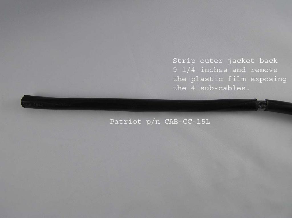
1 RC2000 Cable Preparation ACU Installation Troubleshooting/Alarm codes Patriot 1.8m
2

3
4
5
6
7
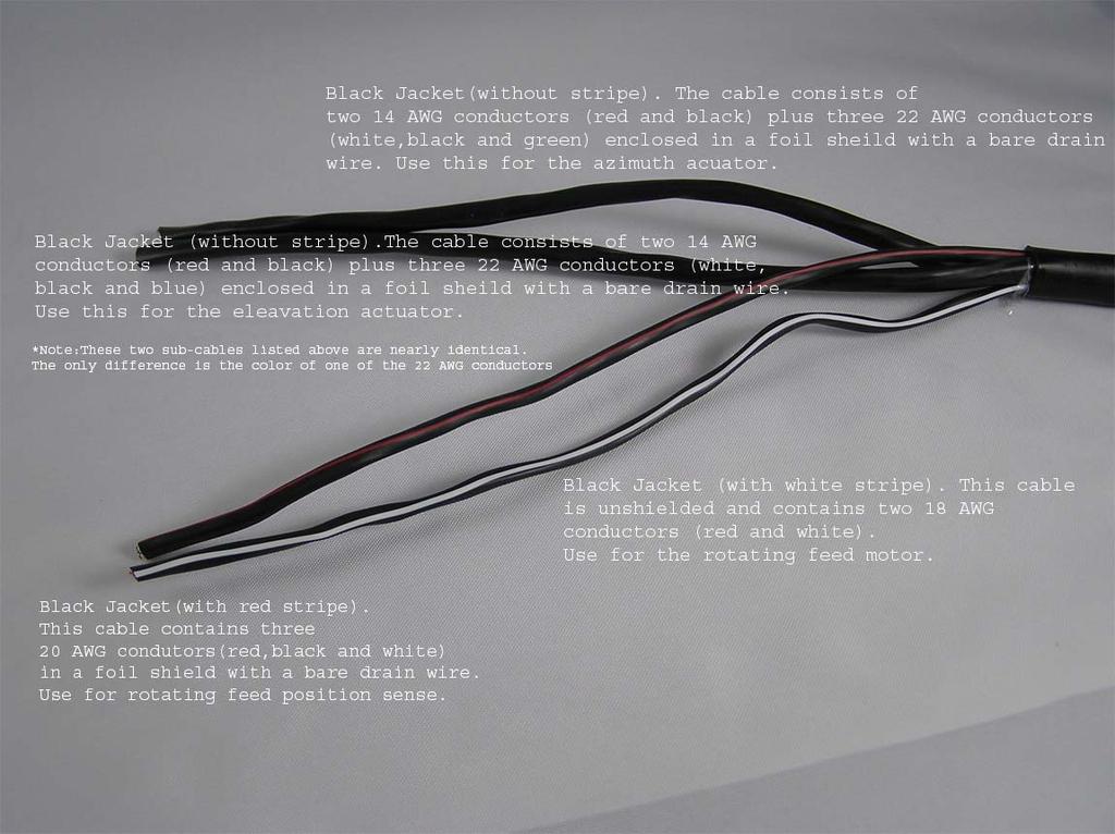
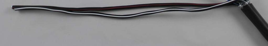
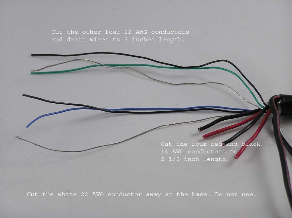
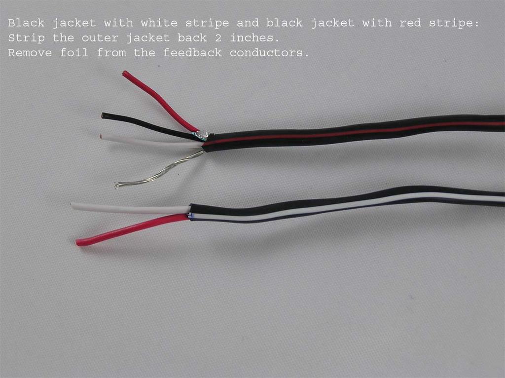
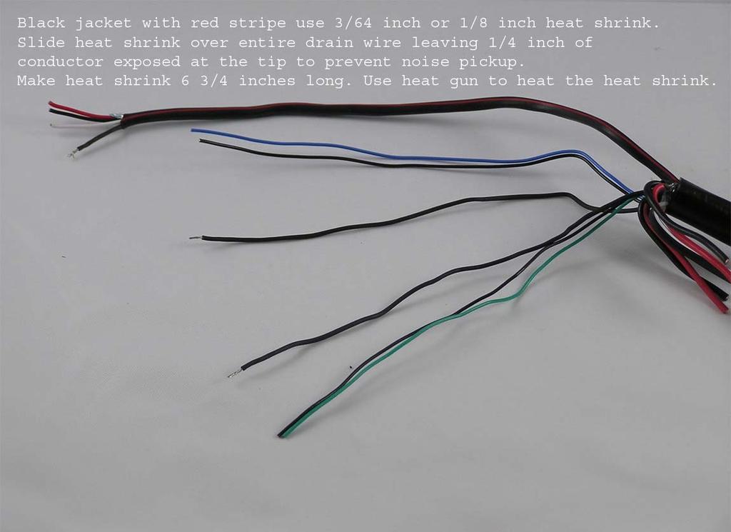
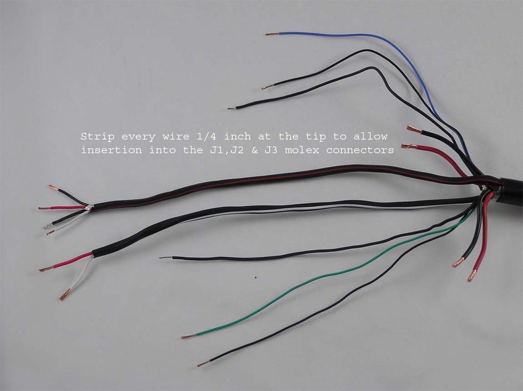
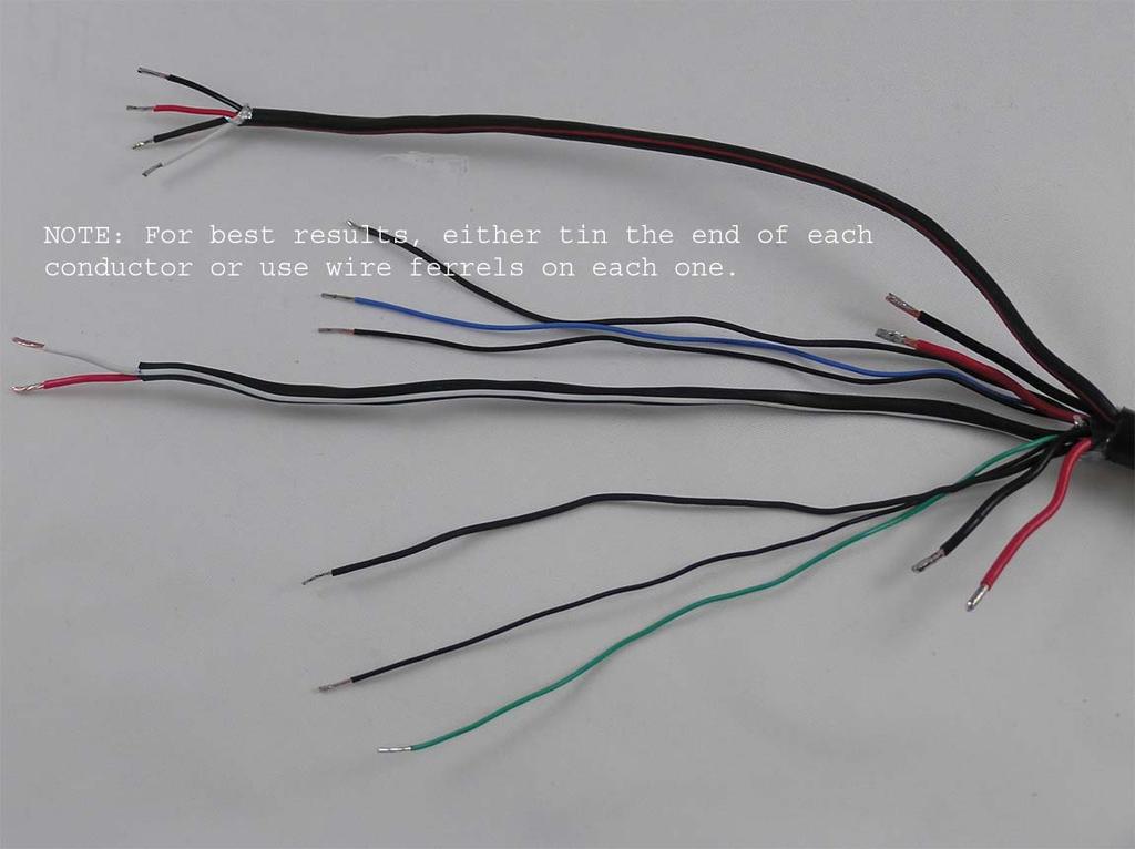
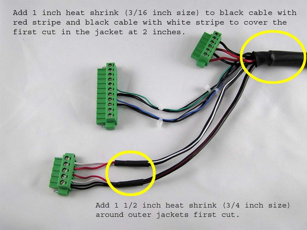
8 Installation Instructions I. Needed equipment: Multimeter, small flathead screwdriver, large phillips screwdriver, test/extra potentiometer (Contelec PD2205h, 5K, 5 turn), allen wrench (to center potentiometer), heat gun for heat shrink, cable jacket strippers (Greenlee p/n 45109), wire cutter, wire stripper (14-22 AWG), crimp connector tool. II. Supplies: Spare fuses (5A slow blow), Heat shrink (Drain wire, Actuator cabling, Pol Pot cable.), 3M UR style connectors for the feed potentiometer connections, Cable Ties (Kingpost, actuator tube, wire strain relief.) III. Installation: A. Install RC2000 into rack using provided rack screws. B. Plug in power cord. Be sure that the line voltage is correct; the installer should check the controller to ensure that the proper line voltage has been selected NOTE: Shielded cables are required for the position sensors. The shields must be connected to pins J1-4 or J1-6 on the back of the controller and must not be connected at the antenna. Shielded cables are required to minimize noise pickup, which can result in antenna positioning errors. At the actuator, the shield should not be allowed to come in contact with any metal objects. At the actuator, insulate the break in the cable jacket with 3/8 inch heat shrink. The RC2000 is equipped with removable terminals: Note: Caution Do not attempt to drive the AZ, EL or POL with an external power supply while the controller is connected to the antenna. This will result in damage to the controller s internal driver circuitry.
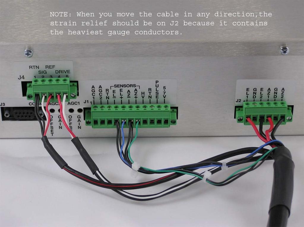
9 A. Connect AZ motor: Az motor Drive: J2 on RC2000: AZ Drive 2; J2:6; black 14 AWG AZ Drive 1; J2:4; red 14 AWG B. Connect AZ sensor: AZ sensor: J1 on RC2000 AZ sensor Pulse; J1:7 AZ sensor Ground; J1:6 AZ sensor Shield; J1:6 shields Azimuth acuator/dc motor Negative terminals Positive terminal AZ position sense/reed switch Green Black No connect Moving the antenna by pressing the AZ/CCW will always result in a decreasing count value. Pressing the AZ/CCW button must result in AZ/CCW movement as seen by an observer behind the antenna. In the Northern hemisphere, AZ/CCW movement corresponds to East movement. Verify correct antenna movement while in LIMTS mode. Be sure to use caution (LIMITS mode has unrestricted movement.) C. Connect EL motor: El motor Drive: J2 on RC2000: EL Drive 2; J2:3 black 14 AWG EL Drive 1; J2:1 red 14 AWG D. Connect EL sensor: El sensor: J1 on RC2000 EL sensor Pulse; J1:5 EL sensor Ground; J1:4 EL sensor Shield; J1:4 shield Elevation Actuator/DC Motor Negative terminals Positive terminal EL Position Sense/Reed switch Blue Black No connect Moving the antenna by pressing the EL/Down will always result in a decreasing count value. Pressing the EL/Down button must result in EL/Down movement as seen by an observer behind the antenna. Verify correct antenna movement while in AZ/EL LIMTS mode. Be sure to use caution (LIMITS mode has unrestricted movement.)
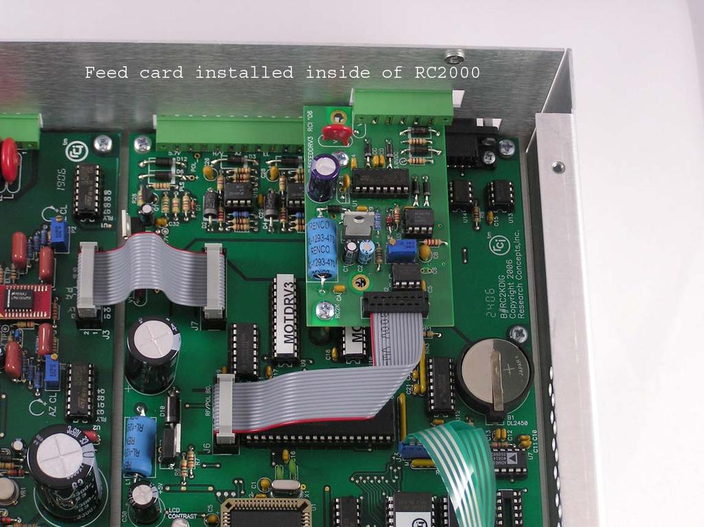
10 IV. 24V Rotating Feed (RC2KPOL): Feed type: TXFD-KLMOTGAM AKU (Single Port) Verify potentiometer is at center position or damage may result to pot. (Refer to Ch. 3, Section 3.3. in user manual) Note: Caution Do not attempt to drive the AZ, EL or POL with a external power supply while the controller is connected to the antenna. This will result in damage to the controller s internal driver circuitry. A. Install Feed Card: Enable the Feed option via CONFIG Mode and use the SCROLL UP or SCROLL DOWN key to bring up the Pol Control menu inside the CONFIG mode. This option should be set to a 1 1 port followed by the ENTER key to save. B. Connect POL motor: Pol motor: Pol Drive 2: J4:5 White 18 AWG Pol Drive 1: J4:4 Red 18 AWG 24VDC Rotating Feed Negative terminals (red) Positive terminals (black) C. Connect Pol Potentiometer: (Contelec PD22005h, 5K, 5 turn) Sensor Ref: J4:3 red CW pin of Pot Sensor Sig: J4:2 white Wiper of Pot Sensor Rtn: J4:1 black CCW pin of Pot Sensor shld: J4:1 shield No connect POL/CCW should increase counts POL/ CW should decrease counts Moving the antenna by pressing the POL/CW key will always result in a decreasing count value. Pressing the POL/CW button must result in POL/CW movement as seen by an observer. Verify correct antenna movement while in POL/LIMTS mode. Be sure to use caution (LIMITS mode has unrestricted movement.)
11 V. Set AZ/EL Limits Caution: In LIMITS mode the user has unrestricted movement of the antenna, there are no software azimuth or elevation limits, and antenna jammed sensing does not take place. When moving the antenna in LIMITS mode, an assistant should be stationed at the antenna to ensure that the antenna does not move past a physical limit. Note also that the CW and CCW polarization keys are active. A. Setting AZ/EL Limits Enter into the AZ/EL LIMITS menu. 1. Jog AZ/CCW/East as far as physically possible without damaging the dish. Press 7 and the AZ CCW limit will automatically set to a position count of Jog AZ/CW/West as far as physically possible without damaging the dish. Press 7 to set the AZ CW/ East limit. 3. Jog back AZ/CCW/East approximately to the middle of the AZ range to ensure to obtain the best EL range of travel. Press BSKP key to confirm 4. Jog EL/Down as far down as physically possible without damaging the dish. Press 9 and the EL/Down limit will automatically set to a position count of Jog EL/Up as far as physically possible without damaging the dish and press 9. This will set the EL/Up limit. Press the BKSP key to confirm *You do not need to set the Geo Elevation. Press MODE and get out of the limits screen. B. Set Pol Limits (RC2KPOL option) 1. First, enable the Pol control option via CONFIG mode. The menu item should be set to a 1 for a one port feed. 2. Press the MODE key and go to the Pol limits menu. The screen reads: Caution-This mode sets CW/CCW Pol Limits: Enter to Continue
12 3. Press ENTER once. The screen now reads: Caution-Unrestricted POL movement, See manual! Enter to Continue. 4. Press Enter; The count value next to PL: should be a 3 digit number. When jogging CCW the count value should increase. CW decreases counts. 5. Skew pol all the way one direction, as far as the feed can physically go, without damaging the feed or the potentiometer, using the 1(POL CCW) and 3 (POL CW) keys. Press the 5 key and this will set the first limit. 6. Skew Pol all the way in the opposite direction as far as the feed can physically go without damaging the feed or the potentiometer. Press the 5 key and this will set the second limit. Note: The Feed position should not be allowed to go less than 25 or greater than 950. If these positions are reached, the pot needs to be centered.( Refer to Ch. 3, Section 3.3. in user manual) VI. Programming Satellites in the non-volatile memory. SETUP mode allows the user to store satellite name, azimuth and elevation positions, and horizontal and vertical polarization positions into non-volatile memory. Once stored in non-volatile memory, satellite positions may be recalled via AUTO mode. SETUP mode is only accessible when the Expert Access mode is active via CONFIG mode. A. 1. While the SETUP screen is active, the user peaks up the antenna on the satellite which is to be stored in the non-volatile memory. The SCROLL UP and SCROLL DOWN keys may be used to select the satellite name (in the SELECT: field) that is stored in the controller s EPROM memory. If the user selects the USER entry from the satellite list, he or she will be prompted to enter a string of characters (after the ENTER key is depressed.) 2. When the ENTER key is depressed, the user is prompted to specify the satellite longitude. If the satellite was not user defined and came from the controller s
13 internal list, the user is presented with a longitude value also from the controller s internal list. 3. Screen reads: Select Band. 0 C, 1 K, 2-C&K. Enter Select 1 for KU band. 4. The next screen prompts the user to specify the Pol CW/CCW position. Skew the POL to the Horizontal position and press the H/7 key. The screen will briefly say H POL set. Skew the POL to the Vertical position and press the V key and the menu will display DATA ACCEPTED. Repeat Steps 1-4 to program in additional satellites. B. After programming in a pair of satellites, the user should repeatedly move between those two satellites (at least 10 times) using the AUTO mode. Note the AZ and EL positions associated with each satellite. At the conclusion of the moves, manually peak up received signal strength on each of the satellites (using MANUAL mode). Verify that the AZ and EL positions that result in peaking signal strength is the same as the position associated with each satellite. IF NOT, position counts from the actuator pulse position sensors are not being accumulated properly. In most cases, this is caused by improper shielding of the sensor cable. Ensure that the actuator drain wires are connected at the back of the controller and that the actuator shield is not allowed to come into contact with any metal object. If the actuator cable is spliced, the shield drain must also be spliced.
14 TROUBLESHOOTING/ALARM CODES The alarm system monitors important system parameters and flashes a message on the bottom line of the LCD display if an error is found. The parameters monitored include the condition of the lithium battery, status of the azimuth and elevation antenna drive systems, and the values of certain variables. Some error codes have priority over others. Alarm conditions are sampled sequentially, with the highest priority sampled first. As corrective action is taken for each error, the code is eliminated, and if there is a lesser error, it will then appear. Note: Caution Do not attempt to drive the AZ, EL or POL with a external power supply while the controller is connected to the antenna. This will result in damage to the controller s internal driver circuitry. SYSTEM ERROR CODES LOW BATTERY The RC2000A constantly monitors the level of the lithium battery. When the power level is low, this error code will appear. Replace the battery with a Duracell DL2450. Make sure that the unit is unplugged from the AC power before removing the cover to change the battery. Take care to hold the battery tab away from the battery housing while replacing the battery and it will not be necessary to reprogram the memory. Since there is a chance that the non-volatile memory will be corrupted when the battery is changed, please refer to the appendix entitled 'Restoring the Non-Volatile Memory' before changing the battery. AZIM LIMITS, ELEV LIMITS One of the antenna software limits has been corrupted. Go into LIMITS mode and reset the software limits. See Section 4.11 POL LIMITS This error indicates that the polarization motor limits have been corrupted when either the RC2KPOL or RC2KHPP option is installed (allowing the RC2000A to interface to a motorized feed with potentiometer feedback). The limits for the polarization motor are set via POL LIMITS mode. See sections 3.3 and
15 ANT AZIM, ANT ELEV, ANT POL These alarm messages indicate that an error has been detected for the axis referenced in the alarm message. When one of these alarms is detected, the axis is disabled. Go to RESET mode (section 4.5) to view the actual fault condition which was detected and to clear the fault. A Reset mode JAMMED indication may mean that the drive breaker is open. This can occur if simultaneous movement is enabled, and the total current draw from both motors exceeds 8 amps. Reset the breaker by pressing it back into place, and disable Simultaneous AZ/EL movement via CONFIG mode. See Section NOTE: The following alarm conditions are cleared by going into CONFIG mode and re-initializing the applicable CONFIG mode items. Access to certain items is controlled by other CONFIG mode items - these controlling items can sometimes make it difficult to clear a CONFIG mode data related alarm. Please review the explanation of the role of these controlling CONFIG mode items in section 2.4. AZIM COUNT, ELEV COUNT The internal position count has been corrupted. Manually find a satellite and go into RE-SYNC mode to update positions. See Section 4.7 AZIM SLOW SPEED, ELEV SLOW SPEED The code entered by the user for the azimuth or elevation slow speed has been corrupted. Go to the corresponding speed mode and reenter the slow speed code. See Section 4.8 AUTOPOL CONFIG DATA The user has the option to configure the system for AutoPol ON or OFF, and to denote a HI or LO level for the vertical polarization. If either of these values is corrupted, this error will appear. Go to CONFIG mode and reenter the correct values. See Section SIMULTANEOUS AZIM/ELEV This error indicates that the value for the Simultaneous Az/El Enable CONFIG mode item has been corrupted. See section GEO POSITION The checksum associated with the GEO COUNT value does not agree with geo position in memory. Move the antenna to the proper GEO POSITION and reenter the GEO ELEV POSITION in the CONFIG mode. Section
16 COMM PORT This alarm indicates that the checksums associated with the CONFIG mode Remote Mode Enable, Comm Port Baud Rate, and Comm Port Address items indicate that at least one of these items is invalid. See section AZ/EL ANGLE DISPLAY This alarm indicates that the CONFIG mode items associated with the display of azimuth and elevation position in an angle format have been corrupted. Please see section POL OPTIONS This error indicates that at least one of the CONFIG mode items associated with the polarization control and display options is invalid. If the system uses a polarotor, these items must still be initialized properly to avoid this error. Please see section AZIM OPTIONS, ELEV OPTIONS This error indicates that at least one of the CONFIG mode items associated with the azimuth or elevation drive options are invalid. Note that all of the config mode items associated with these options must be properly initialized even if the Az/El Drive Options Enable CONFIG mode item is disabled. If this item is disabled and these errors occur, the 'Options Enable item should be enabled to gain access to the other CONFIG mode items associated with these options. These other items can then be initialized to their default values. See section for default values. OPERATIONAL TROUBLESHOOTING TIPS THE CONTROLLER DOES NOT RETURN TO THE PROPER SATELLITE LOCATION (AND IS NOT EVEN CLOSE) When this occurs the controller is generally losing or gaining position counts for a given axis as the antenna moves about that axis. Please review the items mentioned in Section Azimuth and Elevation Position Sense. If the cause of the problem is not found and only one axis is affected, consider replacing the position sense module and/or magnets in the actuator. If both axis are affected the motor drive wires may have to be shielded. This is seldom necessary, but if it is, follows the rules for connecting the shields as outlined in Section 3.2. THE CONTROLLER RETURNS TO APPROXIMATELY THE CORRECT POSITION BUT MUST BE PEAKED MANUALLY TO ACHIEVE A GOOD SIGNAL This is generally an indication of mechanical hysteresis (slop) in either the actuator or the mount. When this occurs the antenna will peak up at one position
17 when approaching the satellite from the azimuth clockwise direction and another when approaching the satellite from the azimuth counter-clockwise direction. To test for this, move the antenna well past the satellite in the azimuth clockwise direction and then manually move the antenna counter-clockwise at slow speed until the peak is reached. Repeat the procedure approaching the satellite from the opposite direction. The difference in azimuth position between the 2 peaks is the mechanical hysteresis. If mechanical hysteresis exists try to eliminate the it. If this is not possible, always approach each satellite from the same direction as it was approached when the satellite was originally programmed into memory. THE ANTENNA AZIM ERROR or ANTENNA ELEV ERROR OCCUR To determine the cause of this error, go the RESET mode. One of the following error messages will be displayed: JAMMED, RUNAWAY, or DRIVE. Here are the likely causes of each of these errors: JAMMED This error indicates that the drive was commanded to move, but movement was not sensed. This can be caused by a mechanical jam at the antenna, or the antenna may be moving but position feedback pulses are not getting back to the controller. Determine which condition exists. If the antenna is not moving there may either be a faulty motor, a wiring problem, a mechanical limit switch has been encountered, or the breaker in the drive circuit has tripped (the breaker may be reset from the back of the unit). If the antenna is moving but position pulses are not reaching the controller, check the sensor wiring of the sensor module in the antenna actuator. RUNAWAY This error occurs when position pulses are recorded but the antenna has not been commanded to move. Check the items listed in Section Azimuth and Elevation Position Sense. If this error occurs just after the antenna has been moving and the drive signals are released, review the 'Deadband CONFIG mode items described at the end of section Also see the paragraph in this section entitled CONFIGURING THE RUNAWAY SENSING SYTEM. DRIVE This error indicates that the controller's electronic over-current sensing has detected an over-current condition and has shut the drive down. There are pots which control the level at which the electronic over-current sensing trips. These pots may have to be adjusted. Please consult the factory. Under no circumstances should the load current supplied by the controller be allowed to exceed 8 amps for more than several seconds. THE AUTOPOL SYSTEM DOES NOT SEEM TO WORK PROPERLY This error is usually caused by the horizontal and vertical polarizations for a given satellite being programmed at the same position. If you turn off the
18 AutoPol function and the controller does not toggle the polarization position as the H and V keys are depressed in MANUAL mode, the polarization positions have probably been programmed at the same value. Other AutoPol problems result from not having a ground wire connected between the satellite receiver and the controller. Please refer to figures 3.2 and 3.3. The AutoPol system should not be enabled when the controller is used with feeds that receive both polarizations simultaneously. WHEN A SATELLITE IS SELECTED VIA AUTO MODE THE CONTROLLER DISPLAYS THE MESSAGE 'ENTRY SELECTED HOLDS INVALID DATA'. Before the controller executes an automatic move it checks to see if the azimuth, elevation, horizontal polarization, and vertical polarization are within their respective limits. If they are not, the error message is displayed. This error can occur if the limits were reset after the satellite position was programmed into memory via SETUP mode. This error can also occur if the state of the POL Control? CONFIG mode item was changed after the satellite was programmed into non-volatile memory. Recovering From Unexpected Memory Upsets The key to restoring the non-volatile memory is getting the azimuth and elevation limits and position counts right. The position counts are initialized to 30 when the azimuth counter-clockwise and down limits are set. If the antenna can be unambiguously placed at the counter-clockwise and down limits, non-volatile memory can be restored quite easily. It is probably a good idea to use a punch or a waterproof magic marker to mark the antenna and mount assembly so that the azimuth counter-clockwise and down limit positions can be identified. In addition, it may useful to identify and mark other places on the mount where slippage could occur. This would allow the mount to be restored to its original configuration. The procedure for restoring non-volatile memory is outlined in Appendix B Field Upgrading. Note that the procedure for restoring non-volatile memory only works if the count characteristics of the actuators are not changed. If the actuator count characteristics are changed, the count values that correspond to the west and up limit will change, as will the positions of all of the satellites
19 1/24 Rough draft_b.p Revision Page 1/25 Revised some spelling. Added in AZ/EL motor and sensor connection per the Patriot 1.8 Navigator schematic. Added in troubleshooting tips. _B.P 1/26 Added in troubleshooting tips about controller not going back to sat. Change Equipment needed from Big Phillips to Large Phillips screwdriver. Changed Pol limits section from 2 port feed to a 1 port feed. I added the word internal in the troubleshooting tips in the paragraph about not using an external battery. Corrected a lot of spelling and grammar mistakes. Added in verify shielding to troubleshooting tips. Added Shielded cables are required to minimize noise pickup which can result in antenna positioning errors at the beginning. B.P. 2/4. Made revisions per S.M.M. Added some equipment and supplies needed. Moved the Troubleshooting tips to beginning. Changed wording of verifying sat after programming. Added in pot limits note. 2/5. Added in all the troubleshooting tip word for word out the manual. 3/09- Added in the Wire colors for the AZ, EL and PL motors and sensors. 3/14- Added in Roman numeral Bullets. 4/11. Added more caution messages about using external power supply. Added more detail to centering the Pot. 4/30 Fixed spelling and grammatical errors. JDK
20 Notes
RC2000A DUAL AXIS ANTENNA CONTROLLER
 RC2000A DUAL AXIS ANTENNA CONTROLLER v 2.32 SEE APPENDIX I FOR UPGRADED FEATURES FOUND IN SOFTWARE VERSIONS 2.6 AND LATER. RESEARCH CONCEPTS, INC. 9501 DICE LANE LENEXA, KANSAS 66215 USA 913-422-0210 WWW.RESEARCHCONCEPTS.COM
Commercial Satellite Antenna Controller for Dual Axis Antennas
 CONTROL-2000A (Specs pg1-2, Manual on pg3) Commercial Satellite Antenna Controller for Dual Axis Antennas FEATURES Automatic Positioning precisely positions antenna with the press of a single key Auto-Pol
RC2000C Polar Satellite Tracking Antenna Controller V 1.31
 RC2000C Polar Satellite Tracking Antenna Controller V 1.31 Contents Subject To Change 02-19-1996 Research Concepts, Inc. 5420 Martindale Road Shawnee, Kansas 66218-9680 USA (913) 422-0210 REVISION HISTORY
9501 Dice Lane Lenexa, KS
 RC1500 Single Axis Antenna Controller Operator's Manual v 1.20 CONTENTS SUBJECT TO CHANGE Jan 29, 2004 RESEARCH CONCEPTS, INC. 9501 Dice Lane Lenexa, KS 66215 913-422-0210 TABLE OF CONTENTS Warranty...
APPENDIX B - MOUNT SPECIFIC DATA For VERTEX 2.4m. SM-LT
 RC3000 Antenna Controller Appendix B-Mount Specific Data B-1 APPENDIX B - MOUNT SPECIFIC DATA For VERTEX 2.4m. SM-LT This appendix describes RC3000 operations unique for the Vertex 2.4m. SM-LT mount. Revision
APPENDIX B - MOUNT SPECIFIC DATA for the Vertex 1.8m. FlyAway
 RC3000 Antenna Controller Appendix B Mount Specific Data 1 APPENDIX B - MOUNT SPECIFIC DATA for the Vertex 1.8m. FlyAway Revision: 14 December 2009, Software Version 1.60 1.1 Appendix B Organization This
RC2500 Satellite Antenna Controller
 RC2500 Satellite Antenna Controller V1.34 Contents Subject to Change 24 January 2012 Research Concepts, Inc. 9501 Dice Lane Lenexa, KS 66215 USA 913.422.0210 WARRANTY One Year Limited Warranty Research
RC2000C Polar Satellite Tracking Antenna Controller V 1.31
 RC2C Polar Satellite Tracking Antenna Controller V 1.31 Contents Subject To Change 2-19-1996 Research Concepts, Inc. 542 Martindale Road Shawnee, Kansas 66218-968 USA (913) 422-21 REVISION HISTORY v 1.1
RC1500 Antenna Controller Implementation
 RC1500 Antenna Controller Implementation The RC1500 is derived from the RC2000C Polar dual axis antenna controller. The RC2000C Polar controller tracks inclined orbit satellites with a polar mount that
RC2500 Satellite Antenna Controller
 RC2500 Satellite Antenna Controller V1.34 Contents Subject to Change 07 June 2010 Research Concepts, Inc. 5420 Martindale Road Shawnee, KS 66218-9680 USA 913.422.0210 WARRANTY One Year Limited Warranty
RC2500 Satellite Antenna Controller
 RC2500 Satellite Antenna Controller V1.20b Contents Subject to Change 19 October 2001 Research Concepts, Inc. 5420 Martindale Road Shawnee, KS 66218-9680 USA (913) 422-0210 WARRANTY One Year Limited Warranty
APPENDIX B - MOUNT SPECIFIC DATA For SweDish Radar Finder
 RC3000 Antenna Controller Appendix F RC3000 Data Sheet 1 APPENDIX B - MOUNT SPECIFIC DATA For SweDish Radar Finder This appendix describes RC3000 operations unique for the SweDish Radar Finder mount. Differences
APPENDIX B - MOUNT SPECIFIC DATA For. Patriot 3.8m Mobile Antenna
 RC Antenna Controller Appendix B Mount Specific Data 1 APPENDIX B - MOUNT SPECIFIC DATA For Patriot.8m Mobile Antenna REVISION HISTORY 29 December 26, Software Version 1.58 27 October 29, Software Version
MFJ ENTERPRISES, INC.
 TM Model MFJ-1924 INSTRUCTION MANUAL CAUTION: Read All Instructions Before Operating Equipment! MFJ ENTERPRISES, INC. 300 Industrial Park Road Starkville, MS 39759 USA Tel: 662-323-5869 Fax: 662-323-6551
MFJ ENTERPRISES, INC.
 Screwdriver Antenna Controller Model MFJ-1926 INSTRUCTION MANUAL CAUTION: Read All Instructions Before Operating Equipment! MFJ ENTERPRISES, INC. 300 Industrial Park Road Starkville, MS 39759 USA Tel:
Procedure, Field Replacement, PCU Kit, XX04
 1. Brief Summary: Troubleshooting document for diagnosing a fault with and replacing the XX04 series PCU assembly. 2. Checklist: Verify Initialization N0 Parameter Pedestal Error Test Motor 3. Theory of
Field Service Procedure PCU Kit, XX97, XX97A & XX00
 1. Brief Summary: Troubleshooting document for diagnosing a fault with and replacing the PCU assembly on the XX97, XX97A and XX00 series antennas. 2. Checklist: Verify Initialization N0 Parameter Pedestal
Field Service Procedure Replacement Pol Motor Kit, Coastal
 1. Brief Summary: Troubleshooting document for diagnosing a fault with and replacing the pol motor on the Coastal series antennas. 2. Checklist: Verify Motor Drive Drive the Pol from Progterm Run the Built
Procedure, Field Replacement, PCU Kit, 6003A/6004, 2406 & 4003A
 1. Brief Summary: Troubleshooting document for diagnosing a fault with and replacing the PCU assembly on the 6003A/6004, 2406 & 4003A series antennas. 2. Checklist: Verify Initialization N0 Parameter Pedestal
4-PC 2.4M ANTENNA SYSTEM W/DUAL AXIS TRACKING MOUNT
 4096-536 Revision E July 13, 2000 ASSEMBLY MANUAL 4-PC 2.4M ANTENNA SYSTEM W/DUAL AXIS TRACKING MOUNT PRODELIN CORPORATION 1500 Prodelin Drive Newton NC 28658 4096-536 PRODELIN CORPORATION 2.4M DUAL AXIS
AMERITRON SDC-102 Screwdriver Antenna Controller
 AMERITRON SDC-102 Screwdriver Antenna Controller INSTRUCTION MANUAL PLEA S E REA D T H IS M A NU A L BEFORE OP ERA T I N G T H IS EQU IP M EN T! 116 Willow Road Starkville, MS 39759 USA 662-323-8211 Version
RC3000/ RC3050 INTERFACE SPECIFICATIONS
 RC3000/ RC3050 INTERFACE SPECIFICATIONS Research Concepts, Inc.; Lenexa, KS 66215; PH: (913)469-4125; FAX: (913)469-4168 WWW.RESEARCHCONCEPTS.COM SUPPORT@RESEARCHCONCEPTS.COM Overview The RC3000 Satellite
RC2K90INT-1, RC2K90INT-2, RC2KINT. RC2000 Antenna Interface Box
 RC2K90INT-1, RC2K90INT-2, RC2KINT RC2000 Antenna Interface Box V. 1.10 Contents Subject to Change 6/28/01 Research Concepts, Inc. 5420 Martindale Shawnee, Kansas; USA PH: (913) 422-0210; FAX: (913) 422-0211
RC3000 Antenna Controller Appendix ASC Integrated ASC Beacon Receiver. Appendix ASC. Integrated ASC Beacon Receiver Option
 Revision: 5 December 2012, software version 1.60 Appendix ASC Integrated ASC Beacon Receiver Option This appendix describes the additional functions provided by the RC3000's integrated Atlantic Satellite
Installation Guide. Hiltron Motorized Antenna Mount HMAM
 HMAM_Install_A.doc Page 1 of 20 Installation Guide for Hiltron Motorized Antenna Mount HMAM HMAM_Install_A.doc Page 2 of 20 Table of Contents 1 Overview...3 2 Unpacking and Inspection...3 3 Contents of
1.1 The RC2000 Antenna Controller Family
 RC2000 Service Manual Chapter 1 Introduction 1 Chapter 1 INTRODUCTION 1.1 The RC2000 Antenna Controller Family The RC2000 antenna controller family consists of the RC2000A, RC2000B POLAR, RC2000B AZ/EL,
Appendix BCN. Integrated Beacon Receiver Option
 Revision: 1 October 2012, software version 1.00 Appendix BCN Integrated Beacon Receiver Option This appendix describes the additional functions provided by the RC4000's integrated Beacon receiver option.
MESA-HPX. Assembly and Installation Manual. w/appendix A for Prodelin Antenna. 901-Manual-MESA-HPX
 MESA-HPX Assembly and Installation Manual w/appendix A for Prodelin Antenna 901-Manual-MESA-HPX Rev 30 March 2011 2 INDEX Installation Cautions 4 Installation Pole Height Orientation of the Mount on the
Com-Trol ADV-6000 Trouble Shooting Guide Click on red text to go to that page in guide
 Com-Trol ADV-6000 Trouble Shooting Guide Click on red text to go to that page in guide Topic Introduction 1 Tool Requirements 1 Trouble Shooting Check List 1 Page(s) Lost communications to controller(s)
LinkAlign-360FER Set-up and Operation Manual
 LinkAlign-360FER Set-up and Operation Manual Proprietary, Nextmove Technologies Page 1 Proprietary, Nextmove Technologies Page 2 Table of Contents General Notes:... 4 Description of items included with
LinkAlign-60RPT Set-up and Operation Manual
 LinkAlign-60RPT Set-up and Operation Manual LinkAlign Setup and Operation Proprietary, Nextmove Technologies Page 1 LinkAlign Setup and Operation Proprietary, Nextmove Technologies Page 2 Description of
User Manual. Last updated on September 5, 2008
 User Manual AlfaSpid by Hy-Gain For use with: AlfaSpid Rotator RAS1 & Controller Rot2Prog by Hy-Gain Azimuth and Elevation rotator and controller AZ/EL RAS1 OR Elevation rotator and controller EL REAL1
INSTALLATION AND OPERATION MANUAL. Multiple-Radio Interface Module 41021G P-26 (11-12) 2012 David Clark Company Incorporated
 2012 David Clark Company Incorporated") INSTALLATI AND OPERATI MANUAL Multiple-Radio Interface Module 41021G-01 19537P-26 (11-12) 2012 David Clark Company Incorporated Table of Contents Cautions and Warnings... 1 Parts/Tools List... 2 Supplied
INSTALLATI AND OPERATI MANUAL Multiple-Radio Interface Module 41021G-01 19537P-26 (11-12) 2012 David Clark Company Incorporated Table of Contents Cautions and Warnings... 1 Parts/Tools List... 2 Supplied
QDV120 Operation and Pointing manual
 QDV120 Operation and Pointing manual MPAD1 Plus OP-080316-E1 page 1 Contents Item Description Page 1.0 Health and Safety for Operators and Installation Staff 3 2.0 Transit case Reflector/Mount/BUC/LNB
Field Service Procedure Level Cage Motor Kit, 2406
 1. Brief Summary: Troubleshooting document for diagnosing a fault with and replacing the level cage motor on the 2406 antenna. 2. Checklist: Verify Initialization Verify Pointing Verify Targeting 3. Theory
116 Willow Road Starkville, MS USA
 AMERITRON SDC-104 Automatic Screwdriver Antenna Controller for Elecraft, Icom, Kenwood and Yaesu Radios INSTRUCTION MANUAL PLEASE READ THIS MANUAL BEFORE OPERATING THIS MACHINE! 116 Willow Road Starkville,
T5x Error Codes DGC5X Console Board W/ ACD3X LCB
 1000320 Rev 2 4/18/06 T5x Error Codes DGC5X Console Board W/ ACD3X LCB Table of Contents Page # Error Code Description 2 Service Information 2-3 Serial Number Information 2 Manager Mode & Engineering Mode
BFS / BFSM SERIES Installation & Maintenance Manual
 Introduction: The BFS / BFSM series electric actuators have battery backup modules for fail safe operation. The BFS series is for two position control and the BFSM series is for proportional control, both
RT-21 Az-El Controller Manual addendum to RT-21 - August 5, 2014
 RT-21 Az-El Controller Manual addendum to RT-21 - August 5, 2014 Overview: The RT-21 Az-El controller consists of two RT-21 units with a shared power supply and shared chassis. The unit features a pair
C-COM Satellite Systems Inc. Page 1 of 39
 Page 1 of 39 inetvu Fly-75V & Fly-98G/H/V & Fly-981 User Manual The inetvu brand and logo are registered trademarks of C-COM Satellite Systems, Inc. Copyright 2006 C-COM Satellite Systems, Inc. 1-877-iNetVu6
APPENDIX SAC Single Axis Compass Option
 RC3000 Antenna Controller Appendix SAC - Single Axis Compass Option 1 APPENDIX SAC Single Axis Compass Option Date: 13 February 2008 Software: 1.59 1.0 INTRODUCTION The Single Axis Compass is a smaller,
AC and DC solutions- Multiple AC and DC solutions available, please contact factory for your application.
 The ATX-3000 antenna tracking controller is a user-friendly microprocessor-based intelligent positioning system to reliably track inclined orbit satellites or for use as a positioner for geosynchronous
815-BR SERVO AMPLIFIER FOR BRUSH SERVOMOTORS
 815-BR SERVO AMPLIFIER FOR BRUSH SERVOMOTORS USER GUIDE September 2004 Important Notice This document is subject to the following conditions and restrictions: This document contains proprietary information
Series 70 Servo NXT - Modulating Controller Installation, Operation and Maintenance Manual
 THE HIGH PERFORMANCE COMPANY Series 70 Hold 1 sec. Hold 1 sec. FOR MORE INFORMATION ON THIS PRODUCT AND OTHER BRAY PRODUCTS PLEASE VISIT OUR WEBSITE www.bray.com Table of Contents 1. Definition of Terms.........................................2
C41 VARIABLE SPEED CONTROL Rev. 1.1
 C41 VARIABLE SPEED CONTROL Rev. 1.1 User manual Rev.1 1. Overview This card lets you control your spindle with PWM and direction signals, as if it was an axis motor. It converts the step signal into and
OPERATION AND MAINTENANCE MANUAL FOR MODELS 7134 & 7134 AST ANTENNA CONTROL SYSTEMS WITH 7150 DRIVE CABINET
 CG-1206 REV B JUNE 99 OPERATION AND MAINTENANCE MANUAL FOR MODELS 7134 & 7134 AST ANTENNA CONTROL SYSTEMS WITH 7150 DRIVE CABINET Controls & Structures Division 1915 Harrison Road Longview, Texas 75604
Antenna Rotator System
 Antenna Rotator System Setup & Hardware Reference Manual RCI-SE August/2002 Rev 2.1a Introduction Thank you for purchasing the ARS interface. At the present day, the ARS is the more powerful, high performance
BandMaster V Manual. Installation
 BandMaster V Manual Installation Installing and configuring the BM-5 BandMaster V is a simple process. All the configuration process is done from the front panel. Installation and configuration steps are
Blue Point Engineering
 Blue Point Engineering Instruction I www.bpesolutions.com Pointing the Way to Solutions! Animatronic Wizard - 3 Board (BPE No. WAC-0030) Version 3.0 2009 Controller Page 1 The Wizard 3 Board will record
RC3000 MOBILE ANTENNA CONTROLLER USER S MANUAL. for the Comtech Transportable Fast Link Antenna (TFLA)
") RC3000 MOBILE ANTENNA CONTROLLER USER S MANUAL for the Comtech Transportable Fast Link Antenna (TFLA) Contents subject to change 17 August 2011 RESEARCH CONCEPTS INC. 5420 Martindale Road Shawnee, Kansas
RC3000 MOBILE ANTENNA CONTROLLER USER S MANUAL for the Comtech Transportable Fast Link Antenna (TFLA) Contents subject to change 17 August 2011 RESEARCH CONCEPTS INC. 5420 Martindale Road Shawnee, Kansas
116 Willow Road Starkville, MS USA
 AMERITRON SDC-104 Automatic Screwdriver Antenna Controller for Elecraft, Icom, Kenwood and Yaesu Radios INSTRUCTION MANUAL PLEASE READ THIS MANUAL BEFORE OPERATING THIS MACHINE! 116 Willow Road Starkville,
Installation & Quick Start Guide CLB2000 Class B AIS Transponder
 Installation & Quick Start Guide CLB2000 Class B AIS Transponder QUICK START CLB2000 - VR1.01 1. Introduction Congratulations on the purchase of your CLB2000 Class B AIS Transponder. It is recommended
Instruction Manual. B Series Program Mode (BLDC Servos)
") Introduction Instruction Manual Congratulations on the purchase of the HFP-30. The HFP-30 is designed to program all Hitec Digital Programmable Servos (D Series, 5xxx/7xxx, and Brushless) as well as test
Introduction Instruction Manual Congratulations on the purchase of the HFP-30. The HFP-30 is designed to program all Hitec Digital Programmable Servos (D Series, 5xxx/7xxx, and Brushless) as well as test
Model 12PR1A. User Manual
 12 Volt Ultra-Portable Antenna Rotor System Single Axis Model 12PR1A User Manual Document Rev 1.1 Copyright 2013-14 Portable Rotation Patent Pending Page 1 Warranty All products sold by Portable Rotation
OVEN INDUSTRIES, INC. Model 5C7-362
 OVEN INDUSTRIES, INC. OPERATING MANUAL Model 5C7-362 THERMOELECTRIC MODULE TEMPERATURE CONTROLLER TABLE OF CONTENTS Features... 1 Description... 2 Block Diagram... 3 RS232 Communications Connections...
RC3000 MOBILE ANTENNA CONTROLLER USER S MANUAL
 RC3000 MOBILE ANTENNA CONTROLLER USER S MANUAL Contents subject to change 1 December 2005 RESEARCH CONCEPTS INC. 5420 Martindale Road Shawnee, Kansas 66218-9680 USA VOICE: (913) 422-0210 FAX: (913) 422-0211
Field Service Spares Procedure Replacement Coax Switch Kit, 8897B, 9497B, 14400B, ST88, ST94 & ST144
 1. Brief Summary: Troubleshooting document for diagnosing a fault with replacing the coax switch assembly on the 8897B, 9497B, 14400B, ST88, ST94 and ST144 antennas. 2. Checklist: Verify the Band of the
MTC-2 highlight features: ACU highlight features: Contents. MTC-2 and ACU User Manual V5.1
 MTC-2 can work alone as a twin motor ECS (electronic speed controller) for RC tanks. When the ACU (auxiliary control unit) is connected, it can also control turret rotation, gun elevation, gun firing,
Quick Start. DTA Self-Install Guide
 Quick Start DTA Self-Install Guide 1 step Installing Your Rainbow HD Digital Transport Adapter (DTA) Your kit contains the following items needed for connecting your DTA to your TV*: DTA Box Coax Cable
Independent Technology Service Inc Independence Ave. Chatsworth, California Toll Free:
 Independent Technology Service Inc. 9182 Independence Ave. Chatsworth, California 91311 www.itscnc.com Toll Free: 1.800.342.3475 NEW Brush Amplifiers For Fadal Machines AMP-0006N-ITS AMP-0021N-ITS NEW
AIU-2 Installation Manual
 AIU-2 Installation Manual RESEARCH CONCEPTS INC. 9501 Dice Lane Lenexa, Kansas 66215 USA VOICE: (913) 422-0210 FAX: (913) 422-0211 www.researchconcepts.com support@researchconcepts.com Contents subject
PAP-240 Three Axis Antenna Pedestal and feed drive
 Présentation générale. ANTENNE MOTORISEE 3 AXES Versions : RxO Ku, RxO Ku&C (4 ports), RxTx Ku (2 ports), RxTx C (2 ports) PAP-240 Three Axis Antenna Pedestal and feed drive The two axis Motorized antenna
IG-2500 OPERATIONS GROUND CONTROL Updated Wednesday, October 02, 2002
 IG-2500 OPERATIONS GROUND CONTROL Updated Wednesday, October 02, 2002 CONVENTIONS USED IN THIS GUIDE These safety alert symbols are used to alert about hazards or hazardous situations that can result in
Jet Central Sequencer Plus
 Jet Central Sequencer Plus Features The Jet Central Sequencer Plus is a multipurpose electronic device, the capabilities of the unit include: Three part sequencer, operating landing gear and two independent
Built-in soft-start feature. Up-Slope and Down-Slope. Power-Up safe start feature. Motor will only start if pulse of 1.5ms is detected.
 Thank You for purchasing our TRI-Mode programmable DC Motor Controller. Our DC Motor Controller is the most flexible controller you will find. It is user-programmable and covers most applications. This
Illustration 1: Wiper Motor Controller, Sensor, and optional programmer. DC Wiper Motor H-Bridge Servo / Speed Controller
 DeviceCraft Revision #2 4/13/2014 Illustration 1: Wiper Motor Controller, Sensor, and optional programmer DC Wiper Motor H-Bridge Servo / Speed Controller P/N 4900 Features: Powerfull servo or reversible
Satellite Terminal. Installation Guide. Release 2.2 Ref. nr
 Satellite Terminal Installation Guide Release 2.2 Ref. nr. 37628 Table of Contents Table of Contents Table of Contents... 2 1 Introduction... 3 1.1 About this Guide... 3 1.2 Material Provided in the Box...
MTC-2 highlight features: ACU for Flakpanzer Gepard highlight features: Contents. MTC-2 and ACU User Manual V4.2 (Flakpanzer Gepard Version)
") This manual is written for the ACU for Flakpanzer Gepard. There are some modifications on usage of servo and LED ports. Please also notice that GSU (gun stabilize unit) is not supported. MTC-2 highlight
This manual is written for the ACU for Flakpanzer Gepard. There are some modifications on usage of servo and LED ports. Please also notice that GSU (gun stabilize unit) is not supported. MTC-2 highlight
Installation & User Manual Radio Remote RCS-10E
 Installation & User Manual Radio Remote RCS-10E SLEIPNER MOTOR AS P.O. Box 519 N-1612 Fredrikstad Norway Tel: +47 69 30 00 60 Fax: +47 69 30 00 70 www.side-power.com sidepower@sleipner.no Made in Norway
USER S MANUAL. C41 VARIABLE SPEED CONTROL Rev. 2 User manual Rev. 1
 USER S MANUAL C41 VARIABLE SPEED CONTROL Rev. 2 User manual Rev. 1 JUNE 2013 USER'S MANUAL TABLE OF CONTENTS Page # Contents 1.0 OVERVIEW... 2 2.0 FEATURES... 2 3.0 SPECIFICATIONS... 3 4.0 INSTALLATION
MTC-2 highlight features: ACU highlight features: Contents. MTC-2 and ACU User Manual V4.0
 MTC-2 can work alone as a twin motor ECS (electronic speed controller) for RC tanks. When the ACU (auxiliary control unit) is connected, it can also control turret rotation, gun elevation, gun firing,
SERIES 70. R SERVO PRO Version 3.0 OPERATION AND MAINTENANCE MANUAL. The High Performance Company
 SERIES 70 R SERVO PRO Version 3.0 OPERATION AND MAINTENANCE MANUAL The High Performance Company Contents 1.0 Safety Instructions - Definition of Terms 2 1.1 Hazard-free Use 2 1.2 Qualified Personnel 2
WARRANTY. Long Range Systems, LLC, 20 Canal St, Suite 4N, Franklin, NH 03235
 WARRANTY Long Range Systems, Inc. warrants the trap release product against any defects that are due to faulty material or workmanship for a one-year period after the original date of consumer purchase.
Microprocessor Control Board Set Up Procedures (OR PLC)
") Microprocessor Control Board Set Up Procedures (OR-00 PLC) SWITCHES/PUSHBUTTONS Push Buttons at display SW Enter button SW Back button SW Down SW UP Back light on/off switch Rotary switches on main board
Microprocessor Control Board Set Up Procedures (OR-00 PLC) SWITCHES/PUSHBUTTONS Push Buttons at display SW Enter button SW Back button SW Down SW UP Back light on/off switch Rotary switches on main board
1525-BRS INFORMATION MANUAL SERV O D YN A M ICS. D y n ad r iv e Ave Crocker Suite 10 Valencia, CA
 28231 Ave Crocker Suite 10 Valencia, CA 91355 818-700-8600 Servodynamics.com INFORMATION MANUAL 1525-BRS SERV O D YN A M ICS U SA www.servodynamics.com D y n ad r iv e Bru sh INDEX Page INTRODUCTION 2
Variable Speed Brushed DC Motor Drive
 The driving force of motor control & electronics cooling. Equinox: Variable Speed Brushed DC Motor Drive Navigator Equinox The Equinox variable speed brushed DC motor drive with Navigator Programmer is
Band-Master ATS Nano Pneumatic Banding Tool Operating Instructions
 Band-Master ATS 601-118 Nano Pneumatic Banding Tool CONTENTS 601-118 Overview... 3 Safety.... 5 Initial Tool Set-up... 5 Regulator assembly mounting... 5 Attach tool head to regulator.... 6 Operating instructions...
A3 Pro INSTRUCTION MANUAL. Oct 25, 2017 Revision IMPORTANT NOTES
 A3 Pro INSTRUCTION MANUAL Oct 25, 2017 Revision IMPORTANT NOTES 1. Radio controlled (R/C) models are not toys! The propellers rotate at high speed and pose potential risk. They may cause severe injury
Channel Remote Programming: For the (35R Motor with or without a Plug) LEFT SIDE AND RIGHT SIDE MOTORS
 LEFT SIDE AND RIGHT SIDE MOTORS") 2016 15 Channel Remote Programming: For the (35R Motor with or without a Plug) LEFT SIDE AND RIGHT SIDE MOTORS Right Side Worms FRONT REMOTE CONTROL BACK Left Side Worms Channel Display Up Stop Down Channel
2016 15 Channel Remote Programming: For the (35R Motor with or without a Plug) LEFT SIDE AND RIGHT SIDE MOTORS Right Side Worms FRONT REMOTE CONTROL BACK Left Side Worms Channel Display Up Stop Down Channel
DSB810A Digital DC Servo Driver Manual V1.0
 User s Manual For DSB810A Digital DC Servo Driver Version 1.0 2007 All Rights Reserved Attention: Please read this manual carefully before using the driver! The content in this manual has been carefully
DC1000 (120VAC) Theory of Operations
 Theory of Operations") DC1000 (120VAC) Theory of Operations The DC1000 is a dynamic DC treadmill designed for a wide range of applications that vary from the medical market to the sports performance market. This theory of operation
DC1000 (120VAC) Theory of Operations The DC1000 is a dynamic DC treadmill designed for a wide range of applications that vary from the medical market to the sports performance market. This theory of operation
HAU Series Controllers
 Instruction, Installation and Operation Guide for: HAU Series Controllers Document Number: 021-00140 Document Revision: B.2 Document Issue Date: Document Creator: G.Gotting Document Creation Date: 4/21/2011
DynaDrive INFORMATION MANUAL SDFP(S)
") DynaDrive INFORMATION MANUAL SDFP(S)1525-17 SERVO DYNAMICS CORP. 28231 Avenue Crocker, Santa Clarita, CA. 91355 (818) 700-8600 Fax (818) 718-6719 www.servodynamics.com INDEX Page INTRODUCTION 2 ELECTRICAL
DynaDrive INFORMATION MANUAL SDFP(S)1525-17 SERVO DYNAMICS CORP. 28231 Avenue Crocker, Santa Clarita, CA. 91355 (818) 700-8600 Fax (818) 718-6719 www.servodynamics.com INDEX Page INTRODUCTION 2 ELECTRICAL
Micromate User Manual
 Microcoin Table of Contents Page Essential Information 2 1.0 Connection and Configuration 3 1.1 Connection 3 1.2 Switch On 4 1.3 Configuration for Use 4 2.0 Check the Configuration of a Validator 5 2.1
USER MANUAL. EPP Intelligent Positioner Control Unit 1/22.
 USER MANUAL - Intelligent Positioner Control Unit 1/22 Table of contents: 1 General... 3 1.1 Safety instructions... 3 2 Application... 4 3 Electrical specifications and terminals... 5 3.1 Control loop...
OPERATION AND MAINTENANCE MANUAL FOR THE MODELS 7134 & 7134 EMT ANTENNA CONTROL SYSTEMS WITH 7150 SERIES III DRIVE CABINET
 CG-1261 REV E SEPT 2005 OPERATION AND MAINTENANCE MANUAL FOR THE MODELS 7134 & 7134 EMT ANTENNA CONTROL SYSTEMS WITH 7150 SERIES III DRIVE CABINET EXPORT CONTROL WARNING - Do not disclose this document
DEC-001 Installation Instructions
 DEC-001 Installation Instructions Skill Level: The installation of this assembly requires a medium level of expertise in working with modern electronic equipment. The use of appropriate tools, correct
Milliamp Calibrator. Model 434. General description. Calibrate with laboratory accuracy. All 4 to 20 ma loop functions
 Milliamp Calibrator Model 434 General description Calibrate Loop Instruments Calibrate and troubleshoot all the signals in a standard 4 to 20 milliamp process control loop with Altek s Model 434 Milliamp
DMX-K-DRV-17 Integrated Step Motor Driver & Basic Controller
 DMX-K-DRV-17 Integrated Step Motor Driver & Basic Controller DMX-K-DRV-17 Manual - 1 - rev 1.35 COPYRIGHT 2015 ARCUS, ALL RIGHTS RESERVED First edition, June 2007 ARCUS TECHNOLOGY copyrights this document.
Instruction Manual for EagleEyes TM FPV Station. Document Version 1.22 (Vector Software Version , or Data Recorder Software Version 10.
 Instruction Manual for EagleEyes TM FPV Station Document Version 1.22 (Vector Software Version 11.78+, or Data Recorder Software Version 10.39+) Introduction Thank you for your purchase! This instruction
Rechargeable Motivia Motorization Made Simple
 Rechargeable Motivia Motorization Made Simple Horizontal Sheer Shadings smithandnoble.com HOW TO OPERATE YOUR MOTORIZED SHADES Operate Your Shade with A Motivia Multi-Channel Remote For added protection,
AutoDAB Connect In-Car DAB Adapter User Guide
 AutoDAB Connect In-Car DAB Adapter User Guide www.autodab.com Table of Content INTRODUCTION... 1 CONTENTS OF PACKAGE... 2 INSTALLATION... 3 OPERATION CONTROLS... 8 STARTING UP THE SYSTEM... 11 USING REMOTE
Boulder 810 Preamplifier
 Boulder 810 Preamplifier Owners Manual 6/8/06 Boulder Amplifiers, Inc. 3235 Prairie Ave. Boulder, CO 80301 www.boulderamp.com APPENDIX RECORDING BOULDER LINK PROGRAMMING REMOTE CONTROL OPERATION GETTING
Electronically Commutated (EC) Motor Control with Solo, Select and Sync PWM Boards
 Motor Control with Solo, Select and Sync PWM Boards") Electronically Commutated (EC) Motor Control with Solo, Select and Sync PWM Boards The Solo, Select and Sync PWM boards provide a pulse-width modulated (PWM) signal to the EC motor to control fan speed.
Electronically Commutated (EC) Motor Control with Solo, Select and Sync PWM Boards The Solo, Select and Sync PWM boards provide a pulse-width modulated (PWM) signal to the EC motor to control fan speed.
Antenna Control. System. Operations Manual
 123T Transportable Antenna Control System 123T Transportable Antenna Control Operations Manual 99-403-0100 Rev B Aug 2005 123T Operations Manual TABLE OF CONTENTS - 123T Revision and Change Record VertexRSI
Copyright 2014 YASKAWA ELECTRIC CORPORATION All rights reserved. No part of this publication may be reproduced, stored in a retrieval system, or
 Copyright 2014 YASKAWA ELECTRIC CORPORATION All rights reserved. No part of this publication may be reproduced, stored in a retrieval system, or transmitted, in any form, or by any means, mechanical, electronic,
WRM-10 TM TRANSFORMER WINDING RESISTANCE METER
 WRM-10 TM TRANSFORMER WINDING RESISTANCE METER USER S MANUAL Vanguard Instruments Company, Inc. 1520 S. Hellman Ave. Ontario, California 91761, USA TEL: (909) 923-9390 FAX: (909) 923-9391 June 2009 Revision
How to Calibrate a CNC Machine's Positioning System
 How to Calibrate a CNC Machine's Positioning System Guide to calibrating the Haas wireless intuitive probing system. Written By: Kim Payne 2018 gunnerautomotive.dozuki.com/ Page 1 of 20 INTRODUCTION Attention:
PLUG N PLAY WATT DIGITAL FM TRANSMITTER. April, 2002 IM No
 PLUG N PLAY 1000 1000 WATT DIGITAL FM TRANSMITTER April, 2002 IM No. 597 9972 OPERATION/FEATURE PROGRAMMING. The PNP 1000 allows the user to select many types of different operating parameters and features.
MLP Troubleshooting Fault Isolation Checklist for MLP
 14 Sep 2006 Page 1 of 8 Fault Isolation Checklist for MLP NOTE: Ensure you have the current version of the Monitor Link Program (MLP) installed on your computer before attempting to use this Checklist.