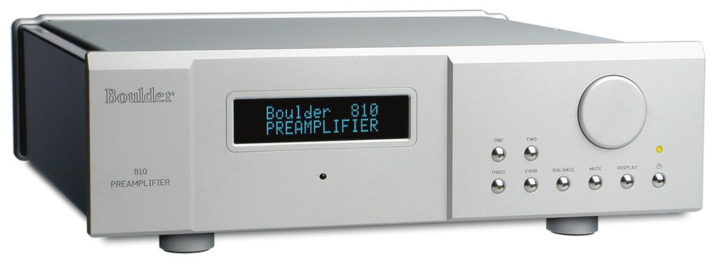
Boulder 810 Preamplifier
|
|
|
- Annabelle Bishop
- 5 years ago
- Views:
Transcription
1
2 Boulder 810 Preamplifier Owners Manual 6/8/06 Boulder Amplifiers, Inc Prairie Ave. Boulder, CO APPENDIX RECORDING BOULDER LINK PROGRAMMING REMOTE CONTROL OPERATION GETTING STARTED

3 B o u l d e r P r e a m p l i f i e r R e a r P a n e l APPENDIX RECORDING BOULDER LINK PROGRAMMING REMOTE CONTROL OPERATION GETTING STARTED
4 TABLE OF CONTENTS GETTING STARTED Introduction Quick Start Placement of the 810 Preamplifier Connecting to the Mains Outlet Polarity Connecting a Balanced Source Connecting an Unbalanced Source Connecting to a Balanced Input Amplifier Connecting to an Unbalanced Input Amplifier Setting the Boulderlink Switch OPERATION Powering Up Input Selections Volume Balance Mute Display APPENDIX RECORDING BOULDER LINK PROGRAMMING REMOTE CONTROL OPERATION GETTING STARTED
5 REMOTE CONTROL Batteries Source Selection Volume, Balance and Mute Polarity PROGRAMMING Input Names Input Polarity Input Level Calibration Input Balance Calibration Theater Mode Start Volume Programming by the Display Button Main Outputs Polarity Boulderlink ID Remote ID Boulderlink Speed Reset to Factory Defaults APPENDIX RECORDING BOULDER LINK PROGRAMMING REMOTE CONTROL OPERATION GETTING STARTED
6 BOULDERLINK Connecting the Boulderlink Connecting 800 Series to 1000 or 2000 Series with Boulderlink Setting Boulderlink Switches Setting Boulderlink ID Numbers Power up via Boulderlink Boulderlink Messages RECORDING Connecting a Recording Device APPENDIX Block Diagram Specifications Troubleshooting Notes APPENDIX RECORDING BOULDER LINK PROGRAMMING REMOTE CONTROL OPERATION GETTING STARTED

7 G E T T I N G S TA RT E D INTRODUCTION Congratulations on your selection of the Boulder 810 Preamplifier. We at Boulder Amplifiers are certain it will provide years of listening pleasure. QUICK START To get started listening, you only need to connect the 810 as you would any other preamplifier, but you should take note of the following. WARNING: The volume control is attractive and because it is optical and has no stops, it is tempting to just spin it. DO THIS ONLY WITH THE POWER OFF! It must be given the respect you would any other volume control with the ability to get loud very quickly. By the time you have turned it up to db with a source turned on, you should be hearing some music. If not, don t proceed any louder until you have solved this problem. See trouble shooting section. For the 810 to work properly, the Boulderlink s MASTER/SLAVE switch should be set to MASTER in most instances. A thorough reading of this manual will definitely enhance your enjoyment of your 810 Preamplifier. 1-1 GETTING STARTED
8 PLACEMENT OF THE 810 PREAMPLIFIER Your Boulder 810 Preamplifier is designed to reduce the effects that external magnetic and radio fields (RF) have on its internal circuitry. While placement is not critical, known magnetic fields should be avoided. Line of sight from the listening position is necessary for the remote control to function properly. Because the preamplifier is heavy, a solid, stable surface should be used. As it will generate some heat, there should be good air circulation around it. You may want to have some access to the rear panels for cable changes. 1-2 GETTING STARTED


9 CONNECTING TO THE MAINS OUTLET Your 810 Preamplifier is supplied with a mains cord suitable to the location where it was purchased. The exact voltage and frequency range is indicated on the rear panel. Make certain that the mains voltage used is within the specifications shown. Also listed are the fuse ratings. There are two fuse holders on the rear of the 810, one for each of the digital and analog power transformers. Use only specified fuses. Check with a qualified service person first. 1-3 GETTING STARTED
10 POLARITY Please note that the 810 Preamplifier conforms to the standard of pin 2 as the positive or hot pin for all analog balanced inputs and outputs. Because input and output polarities are handled through programming setups and the remote control, no concern for polarity is needed while connecting sources. CONNECTING A BALANCED ANALOG SOURCE To fully realize the sonic potential of your 810 Preamplifier, use balanced connections whenever possible. Balanced cables reduce interference from magnetic and RF sources to an absolute minimum. Connect each line source to one of the four inputs provided. Later, you will be able to name each input with the source s name, so you might want to make a list as you connect them. 1-4 GETTING STARTED
11 CONNECTING AN UNBALANCED SOURCE Although the inputs are all of the 3 pin type, an unbalanced source is easily accommodated by using a special cable. This cable has an RCA phono type connector on the source end and a 3 pin connector (for going to an input) on the 810 Preamplifier. The negative input (pin 3) should be wired to ground only at the RCA phono connector. This brings the negative input reference of the 810 to the unbalanced source ground, thus reducing ground loops. Another option for accommodating unbalanced sources is that of the Boulder ABL input adapter. It converts a balanced input into a RCA connector input right at the rear of the 810. Like the above cable, the negative input of the 810 is connected to the ground of the RCA connector. However, this negative side will then share the shield wire with the chassis ground and will not have the best hum rejection. UNBALANCED INPUT CABLE 2-POS INPUT 3-NEG INPUT 1-GROUND 1-5 GETTING STARTED
12 CONNECTING TO A BALANCED INPUT AMPLIFIER With your 810 Preamplifier s balanced output driving a balanced input power amplifier, you can take sonic advantage of short speaker cables and correspondingly longer input cables. With the 810 s low output impedance, distances of more than 50 meters between preamplifier and power amplifier are practical. Connect each amplifier input to the main outputs labeled MAIN OUT. If it is desired to use 2 or more amplifiers such as in bi-amping, splitters will be required. If in doubt, consult your Boulder dealer. 1-6 GETTING STARTED
13 CONNECTING TO AN UNBALANCED INPUT AMPLIFIER A special cable is required to make this connection. This cable connects pin 1 to the shield and pin 2 to the center pin. It leaves the output pin 3 unconnected. Connecting the unused output pin (usually pin 3) to ground will cause excessive ground currents and degrade performance. Use an ohmmeter or continuity checker to determine how a cable is wired. UNBALANCED OUTPUT CABLE 2-POS OUTPUT 3-NEG OUTPUT 1-GROUND LINE PREAMP INPUT 1-7 GETTING STARTED
14 SETTING THE BOULDERLINK SWITCH When using the 810 with only power amplifiers, the Boulderlink MASTER / SLAVE switch should be set to MASTER. For more information on Boulderlink, see the Boulderlink section as indicated by the finger tab below. 1-8 GETTING STARTED

15 OPERATION POWERING UP With all your connections made, you are ready to listen to your Boulder 810 Preamplifier. The power LED will cycle through a variety of colors indicating a standby mode. Power is applied only to the microprocessor during this mode. Press the STANDBY button to turn on the 810. The indicator will change to amber and power will be applied to the audio section. During the power up sequence, the displays at left will be briefly shown. The front panel STANDBY button should be used for everyday turn on and off. This switch mutes the audio, turns off all sections except the microprocessor, and puts the preamplifier in a standby mode. 2-1 OPERATION

16 INPUT SELECTIONS To select an input, press one of the pushbuttons labeled ONE, TWO, THREE or FOUR. The respective input will be shown in the display and that signal will be routed to both the main and record outputs. For example, if input ONE is chosen, 1. INPUT ONE will show in the display. NOTE: There will be a delay when switching from one source to another. This is necessary to allow the circuitry to adjust to the new input source. 2-2 OPERATION

17 VOLUME Because the precise feel of the Boulder 810 s volume control may be different than you are used to, we recommend starting the source device so that an audio signal is fed to the 810 before increasing the volume. The display will show VOLUME INFINITE to indicate maximum attenuation or no sound. By placing a finger at the edge of the rotating control and moving it slowly so it turns in a clockwise direction, the volume will increase and an indication such as VOLUME dB in the display will show the respective volume. At this point you should be listening to music. Each volume step is a change of 0.5 db. WARNING: The volume control must be given the respect you would any other volume control with the ability to get loud very quickly. WARNING: If the input is programmed to be in THEATER MODE, then the volume control will have no effect. For more information, see THEATER MODE in the programming section. 2-3 OPERATION
18 BALANCE To change the level balance, press the BALANCE pushbutton. BALANCE CENTERED will show in the display. Now, rotating the control will change the balance instead of the volume for as long as BALANCE... is displayed. Turning the control counterclockwise (left) will cause an indication such as BALANCE R -2.0dB < in the display. This means that the right channel has been attenuated -2.0 db below the left channel, regardless of volume setting, making the left channel louder. The range of balance offset is limited to db. If the control is then rotated further counterclockwise, the BALANCE RIGHT MUTED< will be displayed to indicate that only the left channel is on. 2-4 OPERATION
19 After several seconds of not changing the balance, the display will return to the VOLUME... indication. You may also return to controlling volume by again pressing the BALANCE pushbutton. The balance resolution is the same as for the volume control, 0.5 db steps. WARNING: If the input is programmed to be in THEATER MODE, then the balance control will have no effect. For more information, see THEATER MODE in the programming section. MUTE To temporarily reduce the volume, press the MUTE pushbutton. VOLUME MUTED will show in the display, replacing the volume indication. Again pressing the MUTE pushbutton will return the volume to normal level. While muted, the level of both channels will be set to -100 db, regardless of volume setting. 2-5 OPERATION

20 DISPLAY The display brightness may be set to any of 4 brightness levels. To change the brightness level, press the DISPLAY pushbutton. DISPLAY 100% will show in the display. Rotate the center control until the desired brightness is obtained such as DISPLAY 50%. The number in the display is the relative brightness. After several seconds of not changing the brightness level, the display will return to the VOLUME... indication. You may also return to controlling volume by again pressing the DISPLAY pushbutton. With the display at a brightness less than that of 100%, any operation of a pushbutton or the volume control will cause the display to go to full brightness for several seconds, and then return to the desired brightness. This ensures that if a function is changed, it will be noticed whether intentional or inadvertent. 2-6 OPERATION


21 R E M O T E C O N T R O L BATTERIES A standard small flat blade screwdriver is required to install the three AAA batteries. To install batteries in the remote control, it is necessary to separate the two sections. WARNING: When opened, the pushbutton balls will be loose and care must be taken to properly retain them. It is recommended to lay the remote control face down on a flat surface so that the balls will stay in position. Then, remove the three screws. Lift off the cover and set aside, making certain that the battery holder comes out from the cover. Install the batteries with the positive (+) terminals facing as indicated on the holder and replace the cover. 3-1 REMOTE CONTROL

22 SOURCE SELECTION To select an input (source) press one of the four buttons on the left side of the remote control. You will now be listening to your desired source, and it will be showing in the display. VOLUME, BALANCE and MUTE To increase the volume, press the button marked with an up arrow. To reduce, press the one marked with a down arrow. Holding either button down will cause the volume to change continuously until released. To change the balance to the left, press the button marked with a left arrow until the display shows BALANCE CENTERED and continue holding until the display shows the desired balance change. Similarly, you may change the balance to the right by holding the button marked with a right arrow. To temporarily mute the audio, press MUTE. To return to normal audio level, again press MUTE. 3-2 REMOTE CONTROL
23 POLARITY NOTE: Often polarity is mistakenly called phase. As phase indicates any angle between two channels from 0 to 360 degrees, the correct term of polarity is preferred to indicate the 180º phase change, or inversion, available in the 810 Preamplifier. By using the remote control, the polarity of both channels may be changed simultaneously at the main outputs during any listening mode. The record outputs are never affected by the polarity setting. To change polarity, press the POL pushbutton on the remote control. POLARITY INVERTED will show in the display. Also, the decimal point after the source abbreviation (e.g. 1.) will change to a - (e.g. 1-) symbol for as long as the polarity remains inverted, even if the source is changed. To return to normal (noninverted) polarity, again press the POL pushbutton. POLARITY NORMAL will show in the display. 3-3 REMOTE CONTROL
24 P R O G R A M M I N G While it is not necessary to ever use any programming functions, you will find they maximize the enjoyment of your Boulder 810 Preamplifier. Each input has several programmable features associated with it. These include assigning an alphanumeric name of your choosing, setting an individual offset attenuation and balance, correcting polarity, and setting theater mode. After holding down an input button until RELEASE BUTTON NOW is displayed, each additional press of this input button will step through the programming options. Changes made during the programming process are automatically stored as they are made. If no changes are made, the original settings are retained. INPUT NAMES For the analog inputs, press and hold the input number you wish to program. If you selected ONE, then PROGRAM INPUT 1 will show in the top display row and CHANGE NAME? NO will show in the bottom display row. Rotating the volume control clockwise will allow you to choose YES if you want to change the name. Again press the same input source number to continue. 4-1 PROGRAMMING
25 If you chose to assign a name, then 1 INPUT ONE will be shown in the bottom display row with a blinking cursor before the name s first character. Rotate the control until the desired character appears. Press the same input source number to accept the displayed character and go to the next character. Continue in this manner until all 17 characters are set. For example, Boulder can be set. NOTE: The space character is just before the exclamation mark (!). INPUT POLARITY Input polarity is used to match the 810 s input polarity to that of each individual source. If uncertain of a particular source s polarity, check the source s owners manual or consult with its manufacturer. After the last character is assigned, pressing the same input source number will make INPUT PIN 2 POSITIVE show in the bottom display row. As you rotate the volume control to INPUT PIN 3 POSITIVE the polarity relays will immediately activate. After the desired polarity is selected, or if no change is desired, press the same input source number. 4-2 PROGRAMMING
26 INPUT LEVEL CALIBRATION Pressing the same input source number will make INPUT LEVEL 0.0dB show in the bottom display row. Rotating the volume control will change the display and the main outputs levels simultaneously. This allows calibration of each input with test tones if desired. For example, setting the display to -6.0dB will allow an input which is twice the voltage of the other inputs to be heard at the same level. A maximum of -20 db may be set. This is easiest to do if you start with the quietest source as your reference, and then adjust the louder sources to match it. 4-3 PROGRAMMING
27 INPUT BALANCE CALIBRATION Pressing the same input source number will make INPUT BAL CENTERED show in the bottom display row. Rotating the volume control will simultaneously change the display and the main output s balance so that the action can be monitored or measured. For example, setting the display to R -9.0dB will make the left channel louder than the right channel. A maximum of -14 db may be set. Again pressing the same input source number will end the programming of this input and initiate a power up sequence. 4-4 PROGRAMMING
28 THEATER MODE When the 810 preamplifier is used in a surround sound theater system, it is normally desired to bypass the volume control, thus letting the surround processor control the volume. WARNING: Setting an input to THEATER MODE forces the volume to unity gain. Use only in conjunction with a surround processor. Again pressing the same input source number will make NORMAL MODE show in the bottom display row. Rotating the volume control will show THEATER MODE-Caution. 4-5 PROGRAMMING
29 START VOLUME When changing inputs, it is possible to have the 810 go to a preset volume level every time the input is selected. Pressing the same input source number will make START VOL? NO CHANGE show in the bottom display row. Rotating the volume control will allow you to choose -50, -60, -70, -80, or -90 db as the new preset level. 4-6 PROGRAMMING
30 PROGRAMMING BY THE DISPLAY BUTTON Several special features are programmed by pressing and holding the DISPLAY pushbutton until the display changes indicating you are in a programming mode. If no action is taken for some time, then the 810 reverts back to normal operation. The sequence is as follows. MAIN OUTPUTS POLARITY The polarity of the main outputs may be adjusted to match the power amplifiers used. For Boulder series 1000 or 2000 amplifiers, it should be set to PIN 2 POSITIVE. If you are using a Boulder 100, 250 or 500 series, this should be set to PIN 3 POSITIVE. For other brands, consult the product s owners manual. If uncertain, set to PIN 2 POSITIVE. Press and hold the DISPLAY pushbutton. OUTPUT POLARITY, PIN 2 POSITIVE will show in the display. Rotate the volume control until the desired polarity is shown in the display. The polarity changes simultaneously with the display. 4-7 PROGRAMMING
31 BOULDERLINK ID Again pressing the DISPLAY pushbutton will make PROGRAM BOULDER LINK, BOULDER LINK ID 20 show in the display. Rotating the volume control changes the ID number. For more information consult the Boulderlink section. Unless you are using two or more 810 Preamplifiers together, this setting should be left at 20. REMOTE ID Again pressing the DISPLAY pushbutton will make PROGRAM REMOTE ID, REMOTE CONTROL ID 5 show in the display. Rotating the volume control changes the ID number. This feature is used in conjunction with a wiring change in the remote control and should always be left set at 5. Consult your dealer to change this setting. BOULDERLINK SPEED Again pressing the DISPLAY pushbutton will make BOULDERLINK SPEED, BAUD-Standard show in the display. Rotating the volume control changes the baud rate. This feature increases the 1012 s compatibility with other brands of equipment. Consult your dealer before changing this setting. 4-8 PROGRAMMING
32 RESET TO FACTORY DEFAULTS Should you wish to have all settings reset to original factory defaults, you may execute a master reset. Normally, this function is not used. Press and hold the STANDBY pushbutton. RESET ALL PARAMETERS, INPUT 1=Y, INPUT 2=N will show in the display. To leave all settings as they currently are, press the TWO pushbutton. To reset all settings, press the ONE pushbutton. WARNING: All settings which you have programmed in will be lost, including the names of each input. The microprocessor and PROM version numbers are momentarily displayed. All other pushbuttons are inoperative during this time. The 810 Preamplifier will then return to normal operating mode and initiate a power up sequence. 4-9 PROGRAMMING

33 BOULDER PRE- AMPLIFIER BOULDERLINK "DAISY CHAIN" BOULDER POWER AMPLIFIER BOULDER POWER AMPLIFIER MASTER SLAVE SLAVE TO ALL OTHER SLAVE UNITS B O U L D E R L I N K Boulderlink is a means of interconnecting most Boulder products so that their microprocessors can talk to each other and pass important information. Among the key features, Boulderlink allows sequential initiation of power amplifiers and other products when the 810 Preamplifier is turned on. Power amplifiers can send messages to the 810 which are then shown on its display. CONNECTING THE BOULDERLINK Turn off all products are to be linked before connecting Boulderlink cables and setting Boulderlink ID and Master/Slave switches. Boulderlink cables in various lengths are available as an accessory from your Boulder dealer. Two connectors are provided on the back of the 810 and other Boulderlink enabled products. All the chassis are connected together in a daisy chain manner. Start by connecting one chassis to another then from that chassis to the next until all are connected. The order does not matter. A special interface may be obtained to enable Boulderlink to be used with other control systems. Contact your Boulder dealer for details. 5-1 BOULDER LINK

34 CONNECTING 800 SERIES TO 1000 OR 2000 SERIES WITH BOULDERLINK If you are using the 810 Preamplifier with other Boulder products, a Boulder Link Adapter Box (BLAB) is required to make the connection. Although the connectors are mechanically different between the series, they are electrically the same, thus allowing the series to be mixed. Contact your Boulder dealer for further information. 5-2 BOULDER LINK
35 SETTING BOULDERLINK SWITCHES Every Boulderlink system must have one MASTER component, and only one component can be set to MASTER. Usually this is the preamplifier. Power amplifiers and other products not having a MASTER/SLAVE switch are not allowed to be MASTER. On the 810, the Boulderlink MASTER/SLAVE switch will normally be set to MASTER. SETTING BOULDERLINK ID NUMBERS Each component is required to have a unique Boulderlink ID number. The 810 ID is preset to 20 at the factory and/or when a master reset sequence is executed. If multiple preamplifiers are connected together, see pages 4-5 through 4-6 for instructions on how to change the ID numbers of the additional units. Each Boulder power amplifier has a thumbwheel switch on the rear panel. Start by setting the first switch to 0 or 1 and then going up from there without any duplication. Use of the lowest numbers will speed up turn on as each amplifier is allowed about 3 seconds before the next. This spreads out the power line inrush currents thus preventing house circuit breakers from unnecessary tripping. Up to 16 power amplifiers may be connected together in one Boulderlink cable daisy chain. 5-3 BOULDER LINK
36 POWER UP VIA BOULDERLINK With each component connected together with a Boulderlink cable, and individually connected to the mains, pressing the 810 s STANDBY pushbutton will initiate the turn on sequence of all components. The first time a MASTER 810 is powered up, it will search for any slave units connected to it. As the Master finds each slave, the slave s ID number will be shown on the display. If any of the connected slaves are amplifiers, then each time the master is turned on it will display WAITING FOR AMPS. Each amplifier will be turned on in the order of their Boulderlink ID. To minimize turn on time, the amplifier s Boulderlink IDs should be set to the lowest sequential numbers possible. For example, use 0, 1, and 2 instead of 13, 14, and 15. An amplifier set to ID 15 will take 47 seconds to turn on. A 810 set to SLAVE, will display THIS UNIT SLAVE #22. If there is no component set to MASTER, the 810 will display THERE IS NO MASTER! In this case, the 810 s MASTER/SLAVE switch should be set to MASTER. It may take up to 30 seconds for the 810 to recognize the switch change. 5-4 BOULDER LINK
37 BOULDERLINK MESSAGES Each component in the system can send a message to the 810 which is then shown on its display. This is particularly helpful in confirming the operating status of each power amplifier in a multiple amplifier system. AMPLIFIER 1 ERROR means that an internal power supply has failed and the amplifier has turned itself off to protect the speakers from damage. AMPLIFIER 1 HAS DC means that it has turned itself off due to a DC offset voltage being detected at its inputs. AMPLIFIER 1 IS HOT means that is has turned itself off due to a higher than normal temperature condition on the heatsinks. AMPLIFIER CLIP means that the amplifier s output has momentarily reached its output voltage limitation. 5-5 BOULDER LINK
38 UNIT 1 IS OFFLINE means that the slave is no longer responding via Boulderlink. Its Boulderlink cable may have become disconnected, or the mains power has been disconnected. UNIT 1 IS ONLINE means that the slave is now responding via Boulderlink in a normal manner and has been recognized by the master. 5-6 BOULDER LINK

39 RECORDING A separate analog output is provided for making recordings or supplying a fixed level output to other system components. CONNECTING A RECORDING DEVICE A recording device may be connected to the 810 Preamplifier. You may use balanced or unbalanced connections as previously described in the sections on connecting power amplifiers. See pages 1-8 and RECORDING
40 7-1 APPENDIX
41 BOULDER 810 PREAMPLIFIER SPECIFICATIONS Balance Line Inputs 4 Main Balanced Outputs 2 Record Balanced Outputs 1 Maximum Input Level 6.0 Vrms Maximum Output Level 14.0 Vrms THD+N, 2V Output, from 20 Hz to 20 khz Less than % Output loaded with 150Ω Less than 1 db distortion change, khz Maximum Voltage Gain, Line input 20 db Volume Range 100 db Volume Steps 0.5 db ±0.05 db (200 Steps) Record Path Gain, Balanced Output 8.5 db Record Path Gain, Unbalanced Output 2.5 db Frequency Response, 20 Hz to 20 khz +0.00, db Frequency Response, -3 db at 0.07 Hz & 250 khz Clip to noise ratio 118 db Crosstalk, L to R or R to L -113 db or better 20 Hz to 20kHz Crosstalk, Adjacent Inputs -113 db or better 20 Hz to 20kHz Input Impedance 100kΩ Balanced Output Impedance 100Ω Balanced, 50Ω Unbalanced Preamp Size, W x H x D 17.0 x 5.50 x inches Weight 18 pounds, Shipping: 26 pounds Power Requirements 100 / 120 / V, Hz, 22 W Max, 3 W Standby. 7-2 APPENDIX
42 TROUBLESHOOTING SYMPTOM CAUSE REMEDY No power indication Preamplifier is not plugged in Connect to an AC outlet Analog source selected, Amber power indication but sound not heard from either channel Amber power indication, but sound not heard from one channel Displays UNIT x ONLINE, then UNIT x OFFLINE continuously Fuse open or missing No signal from source No signal to power amplifier Preamp is defective No signal from one channel of source One Channel is muted by balance control Preamp is defective More than one slave unit has the same Boulderlink ID Reinsert or Replace Fuse Check source controls, cables and connections Check amplifier power status, cables and connections Return to dealer for service Check source controls, cables and connections Push BALANCE and recenter Return to dealer for service Make certain all slave units have a unique Boulderlink ID. See page APPENDIX
43 NOTES 7-4 APPENDIX
Boulder W Mono Power Amplifier
 Boulder 1050 500 W Mono Power Amplifier Owners Manual 4/11/04 Boulder Amplifiers, Inc. 3235 Prairie Ave. Boulder, CO 80301 www.boulderamp.com APPENDIX BOULDER LINK REMOTE CONTROL OPERATION GETTING STARTED
3050 Stereo Power Amplifier
 3050 Stereo Power Amplifier Owners Manual 10/26/2016 Boulder Amplifiers, Inc. 255 Taylor Ave. Louisville, CO 80027 (303) 449-8220 www.boulderamp.com Fault Conditions Boulderlink Appendix Remote Control
Boulder W Class A Stereo Power Amplifier
 Boulder 2060 600 W Class A Stereo Power Amplifier Owners Manual V1.0 10/10/97 TABLE OF CONTENTS GETTING STARTED Placement of the 2050 Power amplifier......................................... 1-1 Connecting
1160 Stereo Power Amplifier
 1160 Stereo Power Amplifier 03/01/2018 Rev. 1.0 P/N: 91055 Boulder Amplifiers, Inc. 255 S. Taylor Ave. Louisville, CO 80027 (303) 449-8220 www.boulderamp.com About About Boulder Amplifiers, Inc. Boulder
USER MANUAL. GOLDMUND TELOS 2500 NextGen Universal Power Amplifier
 USER MANUAL GOLDMUND TELOS 2500 NextGen Universal Power Amplifier Thank you for purchasing the GOLDMUND TELOS 2500 NextGen. You have acquired the best Universal Power Amplifier ever made for professional
GCX. Guitar Audio Switcher OWNER S MANUAL
 GCX Guitar Audio Switcher OWNER S MANUAL Please visit our web site at: www.voodoolab.com Copyright 1998 by Digital Music Corporation. This publication is protected by copyright and all rights are reserved.
ECI 6D. Balanced Integrated Amplifier. Owner's Manual. (with a built-in DAC) ENGLISH
 ENGLISH") ECI 6D Balanced Integrated Amplifier (with a built-in DAC) Owner's Manual EN ENGLISH Unpacking the ECI 6D Immediately upon receipt of the ECI 6D, inspect the carton for possible damage during shipment.
ECI 6D Balanced Integrated Amplifier (with a built-in DAC) Owner's Manual EN ENGLISH Unpacking the ECI 6D Immediately upon receipt of the ECI 6D, inspect the carton for possible damage during shipment.
JEFF ROWLAND D E S I G N G R O U P
 JEFF ROWLAND D E S I G N G R O U P Model 2 Stereo Power Amplifier Owner s Manual Introduction Welcome to the Jeff Rowland Design Group family and congratulations on your purchase of what is unquestionably
USER MANUAL. GOLDMUND MIMESIS 27.5 Analog Preamplifier
 USER MANUAL GOLDMUND MIMESIS 27.5 Analog Preamplifier Thank you for purchasing the GOLDMUND MIMESIS 27.5 Analogue Preamplifier. Please take some time to read this manual. It may provide you with useful
AELIUS YPSILON POWER AMPLIFIER. OWNERS MANUAL V1 01/01/20010 All rights reserved
 AELIUS YPSILON POWER AMPLIFIER OWNERS MANUAL V1 01/01/20010 All rights reserved INTRODUCTION Thank you for trusting YPSILON ELECTRONICS. We assure you that you have made an excellent purchase. Your amplifier
TOA 500 SERIES MIXER POWER AMPLIFIER
 TOA 500 SERIES MIXER POWER AMPLIFIER Operation Instruction Manual A-503A A-506A A-512A Features General Description 1. High quality design and construction. 2. Full frequency response: 50-15,000Hz, ±3dB.
MODEL 3 MONO AMPLIFIER OWNER S MANUAL
 MODEL 3 MONO AMPLIFIER OWNER S MANUAL TABLE OF CONTENTS Introduction Features Unpacking Instructions Installation * Space requirements * A.C. connections Input Impedance Selection Adjustable Gain Signal
USER MANUAL GOLDMUND MIMESIS 29M Millennium Edition Power Amplifier
 USER MANUAL GOLDMUND MIMESIS 29M Millennium Edition Power Amplifier CONGRATULATIONS Thank you for purchasing the Goldmund Mimesis 29M Millennium Edition. You have acquired the best Analogue Power Amplifier
************* OWNER'S MANUAL STAX1250/2 STAX1800/2 STAX2200/2 STAX1200/4 STAX1600/4 STAX2300/4 STAX2000/1D STAX4000/1D STAX5500/1D
 ************* OWNER'S MANUAL STAX1250/2 STAX1800/2 STAX2200/2 STAX1200/4 STAX1600/4 STAX2300/4 STAX2000/1D STAX4000/1D STAX5500/1D INTRODUCTION Power Acoustik amplifiers provide high-performance sound
TABLE OF CONTENTS. 1) Introduction 2. 2) Unpacking your preamplifier 2. 3) Installing the preamp into your system 3
 Introduction 2. 2) Unpacking your preamplifier 2. 3) Installing the preamp into your system 3") TABLE OF CONTENTS 1) Introduction 2 2) Unpacking your preamplifier 2 3) Installing the preamp into your system 3 4) Operation of your preamplifier 6 5) Troubleshooting 8 6) Registration of your preamplifier
TABLE OF CONTENTS 1) Introduction 2 2) Unpacking your preamplifier 2 3) Installing the preamp into your system 3 4) Operation of your preamplifier 6 5) Troubleshooting 8 6) Registration of your preamplifier
USER MANUAL. GOLDMUND METIS 2 Analog Preamplifier
 USER MANUAL GOLDMUND METIS 2 Analog Preamplifier Thank you for purchasing the GOLDMUND METIS 2 Analog Preamplifier. The Goldmund Metis line amplifiers fully incorporate the technological expertise developed
HIGH PERFORMANCE MARINE AUDIO HTX SERIES HTX-1, HTX-2, HTX-4, HTX-6 OWNER'S MANUAL. wetsounds.com
 HIGH PERFORMANCE MARINE AUDIO HTX SERIES HTX-1, HTX-2, HTX-4, HTX-6 OWNER'S MANUAL wetsounds.com CONGRATULATIONS! Thank you for purchasing the Wet Sounds Hydro-Tech TM X (HTX) series amplifier. Wet Sounds
PLANNING YOUR SYSTEM
 INTRODUCTION HERTIAGE amplifiers provide high-performance sound reinforcement for your mobile audio equipment. Its versatility enables compatibility with optional Equalizers, Frequency Dividing Crossover
SLP-2002 Stereo Balanced Vacuum Tube Preamplifier
 SLP-2002 Stereo Balanced Vacuum Tube Preamplifier Fully Balanced Vacuum Tube Line Stage Circuit Design with Cinema Bypass and Remote Volume Control CARY AUDIO DESIGN 1020 GOODWORTH DRIVE APEX, NORTH CAROLINA
SYN-DX SERIES FULL RANGE CLASS-D AMPLIFIERS SYN-DX 2, SYN-DX 2.3 HP, SYN-DX 4, SYN-DX 6 OWNER'S MANUAL. wetsounds.com HIGH PERFORMANCE MARINE AUDIO
 HIGH PERFORMANCE MARINE AUDIO SYN-DX SERIES FULL RANGE CLASS-D AMPLIFIERS SYN-DX 2, SYN-DX 2.3 HP, SYN-DX 4, SYN-DX 6 OWNER'S MANUAL REV DATE FEB 2017 wetsounds.com CONGRATULATIONS! Thank you for purchasing
Kaskode One Phono Preamplifier Owner s Manual
 Kaskode One Phono Preamplifier Owner s Manual www.bandwidthaudio.com sales@bandwidthaudio.com WARNING Configuration of the Kaskode One will require removing the cover of the unit. Before removing the cover
KXR. Owner, s Manual. One hundred KEYBOARD EXTENDED RANGE TYPE: PR 262 P/N
 THE SOUND THAT CREATES LEGENDS KEYBOARD EXTENDED RANGE KXR One hundred TYPE: PR 262 Owner, s Manual P/N 047761 KXR 100 Owner s Manual Congratulations on your purchase of the Fender KXR 100 keyboard amplifier.
Registration 3. Owners Record Setup 4. Unit Connections 6. Front Panel Controls 8. Remote Control 9. Unit Care Technology 10. Designer s Note 12.
 Registration 3. Owners Record Setup 4. Unit Connections 6. Front Panel Controls 8. Remote Control 9. Unit Care Technology 10. Designer s Note 12. Specifications 2 The model and serial numbers are located
USER MANUAL. GOLDMUND TELOS 1000 Universal Power Amplifier
 USER MANUAL GOLDMUND TELOS 1000 Universal Power Amplifier Thank you for purchasing the GOLDMUND TELOS 1000. You have acquired the best Universal Power Amplifier ever made for professional and domestic
Owner s Manual. MOON Series. Titan HT-200. Multi-Channel Power Amplifier
 Owner s Manual MOON Series Titan HT-200 Multi-Channel Power Amplifier Table of Contents Congratulations... 3 Unpacking... 3 Introduction... 4 Installation & Placement... 5 Rear Panel Layout... 6 Connecting
USER MANUAL GOLDMUND TELOS 600 Universal Power Amplifier
 USER MANUAL GOLDMUND TELOS 600 Universal Power Amplifier Congratulations. Thank you for purchasing the GOLDMUND TELOS 600. You have acquired the best Universal Power Amplifier ever made for professional
plifier D-501 otion Am Tactile M
 Tactile Motion Amplifier D-501 IMPORTANT SAFETY INSTRUCTIONS WARNING: 1. Read and keep these instructions for future reference. 2. Do not use this apparatus near water. 3. Clean only with a dry cloth.
LFA4-840 / LFA / LFA LFA1-2000D / LFA1-4000D / LFA1-5500D LFA2-420 / LFA2-600 / LFA2-800 LFA / LFA / LFA / LFA2-2600
 OWNERS MANUAL LFA4840 / LFA41200 / LFA41600 LFA12000D / LFA14000D / LFA15500D LFA2420 / LFA2600 / LFA2800 LFA21250 / LFA21800 / LFA22200 / LFA22600 INTRODUCTION Power Acoustik amplifiers provide highperformance
F O R T H E L O V E O F M U S I C LP100 OWNER'S MANUAL AND INSTALLATION GUIDE INTRODUCTION
 F O R T H E L O V E O F M U S I C LP100 OWNER'S MANUAL AND INSTALLATION GUIDE INTRODUCTION You have purchased an amplifier that leads the way with sound quality, reliability, and features. These high performance
You have acquired the best multi-usage Preamplifier ever made for professional and domestic uses. Please take some
 Congratulations. Thank you for purchasing the Goldmund SR8. You have acquired the best multi-usage Preamplifier ever made for professional and domestic uses. Please take some time to read this manual.
Sound Skulptor MC624 User manual
 Sound Skulptor MC624 User manual 1. Overview The MC624 lets you select one out of six stereo line level audio sources, adjust the level and route it to one out of four stereo amplified monitor pairs. The
User Manual. ia480x Power amplifier
 User Manual ia480x Power amplifier Safety instructions When using this electronic device, basic precautions should always be taken, including the following: 1 Read all instructions before using the product.
USER MANUAL. GOLDMUND TELOS Universal Power Amplifier
 USER MANUAL GOLDMUND TELOS 1000+ Universal Power Amplifier Thank you for purchasing the GOLDMUND TELOS 1000+. You have acquired the best Universal Power Amplifier ever made for professional and domestic
REFERENCE AIRBASS Wireless Subwoofer Volume Control System
 REFERENCE AIRBASS Wireless Subwoofer Volume Control System This device complies with F.C.C. Rules part 15. Operation is subject to the following two conditions: (1) This device may not cause harmful interference
HT Watt 4 Channel Class D amplifier OWNER S MANUAL
 HT-4 600 Watt 4 Channel Class D amplifier OWNER S MANUAL Congratulations! Thank you for purchasing the Wet Sounds Hydro-Tech TM series amplifier. Wet Sounds represents the ultimate in high performance
USER MANUAL. GOLDMUND SR150 2-CHANNEL Universal Power Amplifier
 USER MANUAL GOLDMUND SR150 2-CHANNEL Universal Power Amplifier Congratulations. Thank you for purchasing the Goldmund SR150 2-CHANNEL Universal Power Amplifier. You have acquired the best multi-usage Power
PLA-240. Small Room Loop Amplifier System. USER Manual MAN 211A
 PLA-240 Small Room Loop Amplifier System USER Manual MAN 211A Overview Thank you for purchasing the PLA 240 Small Room Loop Amplifier System. The PLA 240 Loop System provides a practical solution for hearing
HT Watt 6 Channel Class D amplifier OWNER S MANUAL
 HT-6 900 Watt 6 Channel Class D amplifier OWNER S MANUAL Congratulations! Thank you for purchasing the Wet Sounds Hydro-Tech TM series amplifier. Wet Sounds represents the ultimate in high performance
Instruction Kit MIXER AMPLIFIER GT 60C GT 125C. GROMMES-PRECISION SINCE-46
 Instruction Kit GT 60C GT 125C MIXER AMPLIFIER GROMMES-PRECISION 1-800-SINCE-46 www.grommesprecision.com Thank you for purchasing from Grommes~Precision! Grommes~Precision and its commercial audio division,
USER MANUAL. GOLDMUND SRM250 Power Amplifier
 USER MANUAL GOLDMUND SRM250 Power Amplifier Congratulations. Thank you for purchasing the Goldmund SRM250 Power Amplifier. You have acquired the best Analog Power Amplifier ever made for professional and
USER MANUAL. GOLDMUND Metis 5 Analog Integrated Amplifier
 USER MANUAL GOLDMUND Metis 5 Analog Integrated Amplifier Thank you for purchasing the Goldmund METIS 5 Analog Integrated Amplifier. The Goldmund Metis line amplifiers fully incorporate the technological
F O R T H E L O V E O F M U S I C SERIES 218 DPS200 OWNER'S MANUAL AND INSTALLATION GUIDE INTRODUCTION
 F O R T H E L O V E O F M U S I C SERIES 218 DPS200 OWNER'S MANUAL AND INSTALLATION GUIDE INTRODUCTION You have purchased an amplifier that leads the way with sound quality, reliability, and features.
PST 100 YPSILON PRE AMPLIFIER MKII. OWNERS MANUAL V2 01/01/2010 All rights reserved
 PST 100 YPSILON PRE AMPLIFIER MKII OWNERS MANUAL V2 01/01/2010 All rights reserved INTRODUCTION Thank you for trusting YPSILON ELECTRONICS. We assure you that you have made an excellent purchase. Your
Owner s Manual B 300 B 600 B 900 B 1200 B 1500 B 902 B 1202 B 1802 B300 B1802
 Owner s Manual B 300 B 600 B 900 B 1200 B 1500 B300 B 902 B 1202 B 1802 B1802 WARNING B 300 / B 600 / B 900 / B 1200 / B 1500 / B 902 / B 1202 / B 1802 Table of Contents Table of Contents Introduction
MZ2 HEADPHONE AMPLIFIER, PREAMP, & STEREO AMPLIFIER USER GUIDE
 MZ2 HEADPHONE AMPLIFIER, PREAMP, & STEREO AMPLIFIER USER GUIDE Linear Tube Audio Takoma Park, MD, USA WARNING: For safety, the cover of this amplifier should be secured at all times. DC voltages as high
IMPORTANT SAFETY INSTRUCTIONS
 IMPORTANT SAFETY INSTRUCTIONS When using this electronic device, basic precautions should always be taken, including the following: 1. Read all instructions before using the product. 2. Do not use this
0.0 Table of contents of this manual Page 01
 0.0 Table of contents of this manual Page 01 1.0 Setting up the ASR Mini-Basis Page 02 2.1 Important safety precautions 2.0 Connecting the ASR Mini-Basis Page 03 2.1 Connecting to a pre- or an integrated
HQ-31 HQ-15 USER S GUIDE SINGLE CHANNEL 31 BAND 1/3 OCTAVE GRAPHIC EQUALIZER DUAL CHANNEL 15 BAND 2/3 OCTAVE GRAPHIC EQUALIZER
 HQ-31 SINGLE CHANNEL 31 BAND 1/3 OCTAVE GRAPHIC EQUALIZER HQ-15 DUAL CHANNEL 15 BAND 2/3 OCTAVE GRAPHIC EQUALIZER USER S GUIDE GENERAL INFORMATION SINGLE CHANNEL 31 BAND 1/3 OCTAVE GRAPHIC EQUALIZER WITH
Professional Power Amplifier
 SERVICE FOR YOURCBU PRODUCT (International) For service, please contact the CBU distributor in your country through the dealer from whom you purchased this product. DO NOT ATTEMPT TO SERVICE THIS UNIT
POWER AMPLIFIER. Owner s Manual POWER AMPLIFIER R 20 CLIP POWER TEMP PROTECTION 6 POWER. Keep This Manual For Future Reference.
 POWER AMPLIFIER Owner s Manual POWER AMPLIFIER POWER 20 5 L CLIP R 20 5 TEMP 25 0 25 0 PROTECTION 0 LEVEL 0 6 6 POWER 40 40 ON OFF L 0 db R 0 Keep This Manual For Future Reference. E WARNING: THIS APPARATUS
441 DUAL CHANNEL 15 BAND 2/3 OCTAVE GRAPHIC EQUALIZER 451 SINGLE CHANNEL 31 BAND 1/3 OCTAVE GRAPHIC EQUALIZER
 441 DUAL CHANNEL 15 BAND 2/3 OCTAVE GRAPHIC EQUALIZER 451 SINGLE CHANNEL 31 BAND 1/3 OCTAVE GRAPHIC EQUALIZER 455 DUAL CHANNEL 31 BAND 1/3 OCTAVE GRAPHIC EQUALIZER The new ART 400 Series of Precision Graphic
TA5604 Owner s Manual
 TA5604 Owner s Manual Introduction Thank you for choosing MTX to help reach the ultimate goal with your vehicle. Adding MTX amplifiers and matching MTX speakers and subwoofers with StreetWires connections
Installation & User Guide. For Powering Distributed Audio Systems A45-X2 TWO CHANNEL AMPLIFIER
 Installation & User Guide For Powering Distributed Audio Systems TWO CHANNEL AMPLIFIER A45-X2 A45-X2 TWO CHANNEL AMPLIFIER TABLE OF CONTENTS Features...1 Product Overview...2 Package Contents...4 Preparing
MC2301. Features and Benefits. Promotional Highlights TUBE POWER AMPLIFIER MCINTOSH LABORATORY INC., 2 CHAMBERS STREET, BINGHAMTON, NEW YORK 13903
 MC2301 Product Preview Page 1 McIntosh Laboratory, Inc., Binghamton, NY 13903 Design Engineering Department PRODUCT PREVIEW MC2301 TUBE POWER AMPLIFIER Project 1336 Promotional Highlights 300 Watts Mono
TA4252 Owner s Manual
 TA4252 Owner s Manual Introduction Thank you for choosing MTX to help reach the ultimate goal with your vehicle. Adding MTX amplifiers and matching MTX speakers and subwoofers with StreetWires connections
TA3202 Owners Manual. Input Sensitivity Switch: 100mV-1V/1V-10V Crossover: Hi, 12dB / Low, 85Hz, Defeatable
 TA3202 Owners Manual Introduction Thank you for choosing MTX to help reach your ultimate goal with your vehicle. Adding MTX amplifiers and matching MTX speakers and subwoofers with StreetWires connections
MA6004 MA6002 MARINE AUDIO POWER AMPLIFIER OWNER S MANUAL. The Official Brand of Live Music.
 MA6004 MA6002 MARINE AUDIO POWER AMPLIFIER OWNER S MANUAL The Official Brand of Live Music. INSTALLATION THANK YOU for purchasing a JBL marine amplifier. In order that we may better serve you should you
TOA NEW 900 SERIES MIXER PREAMPLIFIER M-900A
 Operation Instruction Manual TOA NEW 900 SERIES MIXER PREAMPLIFIER M-900A Features General Description 1 6-channel mixer preamplifier 2 Wide frequency response; 20 20,000Hz, ±1dB 3 Low distortion and noise
PROAUDIO AMPLIFIERS BI2400PRO BI3400PRO
 LIMITED WARRANTY Bass Inferno warrants any products purchased in the U.S.A. from an authorized Bass Inferno dealer. All products are warranted to be free from defects in material and workmanship under
GOLDMUND MIMESIS SRM2.3 MONO AMPLIFIER
 GOLDMUND MIMESIS SRM2.3 MONO AMPLIFIER 1 GOLDMUND MIMESIS SRM2.3 MONO AMPLIFIER USER MANUAL ATTENTION : No connection or manipulation must be done before reading those instructions. Damage to the amplifier
REVAMP2600 Instruction manual
 REVAMP2600 Instruction manual REVAMP2600 Instruction manual 3 REVAMP2600 MANUAL 4 PROFESSIONAL POWER AMPLIFIER Safety first! Caution! This professional device needs to be installed by qualified personnel
impact VC-500LR Monolight INSTRUCTIONS
 impact lighting equipment and accessories VC-500LR Monolight INSTRUCTIONS Congratulations on your purchase of the Impact VC-500LR Monolight. We feel that it will contribute much to your photographic skill
O W N E R ' S M A N U A L
 O W N E R ' S M A N U A L Z p r e Z o n e P r e a m p l i f i e r w w w.parasound.com Table of Contents Front Panel, Rear Panel, and Remote Control Drawings... 4 Introduction... 5 Unpacking, Installation
UNDERGROUND INSTRUCTION & INSTALLATION MANUAL. active. enclosure MODEL: FU10A, FU12A, FU12TA
 UNDERGROUND INSTRUCTION & INSTALLATION MANUAL active enclosure MODEL: FU10A, FU12A, FU12TA 2 Thank you for purchasing this FLI UNDERGROUND subwoofer enclosure. It will provide you with years of trouble
PLUG N PLAY WATT DIGITAL FM TRANSMITTER. April, 2002 IM No
 PLUG N PLAY 1000 1000 WATT DIGITAL FM TRANSMITTER April, 2002 IM No. 597 9972 OPERATION/FEATURE PROGRAMMING. The PNP 1000 allows the user to select many types of different operating parameters and features.
Big Bang. B B O w n e r s M a n u a l. Power Amplifiers. SpeakerCraft BB2125 POWER ACTIVE PROTECTION L
 Big Bang Power Amplifiers SpeakerCraft BB2125 ACTIVE POWER PROTECTION L R B B 2 1 2 5 O w n e r s M a n u a l SAFETY INSTRUCTIONS APPLICABLE FOR USA, CANADA OR WHERE APPROVED FOR USAGE CAUTION: To reduce
VSR 5 U Microphone Preamplifier. Operating Manual
 VSR 5 U Microphone Preamplifier Operating Manual 2 3 Contents Contents Page Introduction 5 The Power supply 5 The Signal Path and Operating controls 6 Notes on EMC, Ground Lift Switch 9 Specifications
SA-103. Power Amplifier Instruction Manual. The heart of music
 SA-103 Power Amplifier Instruction Manual The heart of music www.pliniusaudio.com CONTENTS Introduction 2 Design Philosophy 3 Unpacking 4 Placement & Ventilation 4 Precautions 5 Amplifier Features Front
AMPLIFIERS BI BI BI BI4400.4
 LIMITED WARRANTY Bass Inferno warrants any products purchased in the U.S.A. from an authorized Bass Inferno dealer. All products are warranted to be free from defects in material and workmanship under
AMPLIFIERS. Bi2200Tx Bi4200Fx. Bi1400Mx Bi2400Mx Bi3000Mx
 LIMITED WARRANTY Bass Inferno warrants any products purchased in the U.S.A. from an authorized Bass Inferno dealer. All products are warranted to be free from defects in material and workmanship under
T25-35SA Subaudible Tone Decoder
 T25-35SA Subaudible Tone Decoder The Mueller Broadcast Design T25-35SA subaudible tone decoder provides a simple and reliable way to detect the 25 and 35 Hz control tones sent by many satellite-delivered
Microphone audio, from the MFJ-1278B to your transmitter. Ground, audio and PTT common. Push-to-talk, to allow the MFJ-1278B to key your transmitter.
 Computer interfacing, covered in the previous chapter, is only half the interfacing task. The other half is connecting your MFJ-1278B to your radios. MFJ-1278B Radio Ports Interfacing the MFJ-1278B to
model 101 single channel microphone preamplifier owner s manual Rev C
 2434 30th street, boulder, CO 80306-0204 USA tel 303.443.7454 fax 303.444.4634 info@gracedesign.com / www.gracedesign.com single channel microphone preamplifier Rev C all contents Grace Design/ Lunatec
REF1000. Mono Audio Power Amplifier
 User's Guide and Operating Information REF1000 e.one Series Mono Audio Power Amplifier Bel Canto Design, LTD. 212 Third Avenue North Minneapolis, MN 55401 Phone: (612) 317.4550 Fax: (612) 359.9358 www.belcantodesign.com
22A3 Monaural Amplifier Owner s Manual
 22A3 Monaural Amplifier Owner s Manual www.bandwidthaudio.com sales@bandwidthaudio.com WARNING Never power on the amplifier without connecting a proper load Failure to do so will result in permanent damage
Owner s Manual.
 P Z R 6 0 0 A m p l i f i e r P Z R 1 0 0 0 A m p l i f i e r Owner s Manual www.pyleaudio.com Your New Pyle Pro PZR series P.A. Amplifier gives you the power and versatility you need in a professional
audionet PAM G2 User s Manual Phono Preamplifier for MC / MM
 audionet PAM G2 Phono Preamplifier for MC / MM User s Manual 1 2 Contents 1 Preface... 5 1.1 Included... 6 1.2 Transport... 6 2 Overview front panel... 7 3 Overview back panel... 8 4 Installation and power
Owner s manual. SDA 2175 Semi Digital Amplifier
 Owner s manual SDA 2175 Semi Digital Amplifier 2 Table of Contents Operating Voltage 4 Unpacking the SDA 2175 4 Serial Number Registration 4 Introduction 5 Accessories 6 Front Panel 7 - Controls 7 Rear
E-400 endstufe. user manual
 E-400 endstufe user manual Musikhaus Thomann e.k. Treppendorf 30 96138 Burgebrach Germany Telephone: +49 (0)9546 9223-66 email: info@thomann.de Internet: www.thomann.de 02.12.2011 Table of contents Table
E-400 power amplifier. user manual
 E-400 power amplifier user manual Musikhaus Thomann e.k. Treppendorf 30 96138 Burgebrach Germany Telephone: (09546) 9223-0 E-mail: info@thomann.de Internet: www.thomann.de 07.03.2014, ID: 173888 Table
Model 7000 Low Noise Differential Preamplifier
 Model 7000 Low Noise Differential Preamplifier Operating Manual Service and Warranty Krohn-Hite Instruments are designed and manufactured in accordance with sound engineering practices and should give
PowerShare PS604A adaptable power amplifier
 Product Description Bose delivers 600 watts for fixed-install applications. Through patented technology, total amplifier power is shared across all output channels, allowing installers the freedom to utilize
Model 12 Mono Power Model Amplifier 12 Owner s Manual
 Model 12 Mono Power Model Amplifier 12 Mono Owner s Power Manual Amplifier Owner s Manual Introduction Welcome to the Jeff Rowland Design Group family and congratulations on your purchase of what is unquestionably
TA 450 MK-X TA 600 MK-X TA 1050 MK-X TA 1400 MK-X TA 2400 MK-X power amplifier. user manual
 TA 450 MK-X TA 600 MK-X TA 1050 MK-X TA 1400 MK-X TA 2400 MK-X power amplifier user manual Musikhaus Thomann e. K. Treppendorf 30 96138 Burgebrach Germany Telephone: +49 (0) 9546 9223-0 E-mail: info@thomann.de
USER MANUAL. GOLDMUND TELOS 590 NextGen Integrated Amplifier
 USER MANUAL GOLDMUND TELOS 590 NextGen Integrated Amplifier Congratulations. Thank you for purchasing the Goldmund TELOS 590 NextGen. You have acquired the best multiusage ever made for professional and
EXOS TM. User s Manual. Electronic Crossover for the STATEMENT. Electrostatic Hybrid High Resolution Loudspeaker System. electronic crossover
 EXOS TM User s Manual Electronic Crossover for the STATEMENT e v o l u t I o n 2 Electrostatic Hybrid High Resolution Loudspeaker System electronic crossover -8-4 0 4 balanced on 50Hz CONTOUR db MUTE BASS
CLASS A DUAL TRANSFORMER COMPRESSOR OWNER S MANUAL
 LIMINATOR CLASS A DUAL TRANSFORMER COMPRESSOR OWNER S MANUAL TABLE OF CONTENTS SECTION PAGE INTRODUCTION 2 INSTALLATION 3 FRONT PANEL CONTROLS 4 OPERATION 5 SPECIFICATIONS 7 WARRANTY AND REGISTRATION 8-1
IA SERIES OWNER'S MANUAL
 IA SERIES OWNER'S MANUAL overview OVERVIEW / CONTACT contact Congratulations and thank you for purchasing an Incriminator Audio amplifier for your new automotive sound system. Like all of Incriminator
ALM473 DUAL MONO \ STEREO AUDIO LEVEL MASTER OPERATION MANUAL IB
 ALM473 DUAL MONO \ STEREO AUDIO LEVEL MASTER OPERATION MANUAL IB6408-01 TABLE OF CONTENTS GENERAL DESCRIPTION 2 INSTALLATION 2,3,4 CONNECTION AND SETUP 4,5,6,7 FUNCTIONAL DESCRIPTION 8,9 MAINTENANCE 9
Block-800B bass head. user manual
 Block-800B bass head user manual Musikhaus Thomann Thomann GmbH Hans-Thomann-Straße 1 96138 Burgebrach Deutschland Telephone: +49 (0) 9546 9223-0 E-mail: info@thomann.de Internet: www.thomann.de 08.03.2018,
TU 970 OWNER S MANUAL
 TU 970 OWNER S MANUAL Power for the Digital Revolution Table of Contents 3 Introduction 4 Front Panel Controls 5 Rear Panel Connections 6 Remote Control Functions 7 Installation and Connections 8 Operation
Opus 21 s80 Integrated Amplifier Owner's Manual
 Opus 21 s80 Integrated Amplifier Owner's Manual r e s o l u t i o n From all of us at Resolution Audio, thank you for choosing the Opus 21 s80 amplifier. We went to great lengths to design and produce
Owner s Manual 900.4M. 4 ch MARINE amplifier. reaudio.com
 Owner s Manual 900.4M 4 ch MARINE amplifier reaudio.com THANK YOU for purchasing RE AUDIO Bluetooth MARINE amplifiers BT-900.4M. With almost no sacrifice on sound quality, BT-900.4M easily plays the music
Features, Benefits, and Operation
 Features, Benefits, and Operation 2013 Decibel Eleven Features, Benefits, and Operation Contents Introduction... 2 Features... 2 Top Panel Controls... 3 Operation Basics... 4 Connections... 5 Rear Panel
a Loop System LA240 User manual ACCESS TO SOUND
 a Loop System LA240 User manual ACCESS TO SOUND The LA240 Loop System provides a practical solution for hearing aid users to listen more easily to their TV or Audio equipment via the T or Loop program
Signature Century Manual. Ultra-high resolution stereo power amplifier by Frans de Wit.
 Signature Century Manual. Ultra-high resolution stereo power amplifier by Frans de Wit. Congratulations on purchasing this extremely capable; exquisitely built state-of-the-art stereo power amplifier.
OWNER S MANUAL CPS 1 / CPS 2 CONTRACTOR PRECISION SERIES
 OWNER S MANUAL CPS 1 / CPS 2 CONTRACTOR PRECISION SERIES CONTENTS Introduction................................................................... 9 Front Panel...................................................................
SAGA PRO SERIES STEREO POWER AMPLIFIER OPERATION MANUAL
 SAGA PRO SERIES STEREO POWER AMPLIFIER OPERATION MANUAL INSTALLATION Use care in unpacking the amplifier, and be sure to save the carton and packing materials so that you can use them for moving, storing,
SETUP and OPERATING MANUAL ADVANCED MULTI-CHANNEL VEHICLE INTERCOM SYSTEM (AMCVIS)
") SETUP and OPERATING MANUAL Sept 23, 2010 Rev D ADVANCED MULTI-CHANNEL VEHICLE INTERCOM SYSTEM (AMCVIS) with DIGITAL CREW CONTROL and RADIO BRIDGING The AMCVIS was designed, manufactured and is supported
SETUP and OPERATING MANUAL Sept 23, 2010 Rev D ADVANCED MULTI-CHANNEL VEHICLE INTERCOM SYSTEM (AMCVIS) with DIGITAL CREW CONTROL and RADIO BRIDGING The AMCVIS was designed, manufactured and is supported
REVAMP2250 Instruction manual
 REVAMP2250 Instruction manual REVAMP2250 Instruction manual 3 REVAMP2250 Manual 4 DIGITAL POWER AMPLIFIER Safety first! Caution! This professional device needs to be installed by qualified personnel only.