Built-in soft-start feature. Up-Slope and Down-Slope. Power-Up safe start feature. Motor will only start if pulse of 1.5ms is detected.
|
|
|
- Allison Weaver
- 5 years ago
- Views:
Transcription


1 Thank You for purchasing our TRI-Mode programmable DC Motor Controller. Our DC Motor Controller is the most flexible controller you will find. It is user-programmable and covers most applications. This Product has a limited warranty and as with any product, you must use it within the stated specifications and have a basic understanding of electricity and electronics. Before you start connecting the Servo Controller, please read the specs list below. Features and specifications: Input 1: RC Pulse 0.9ms to 6 Volts or less. Input 2: Potentiometer 5 to 25 K Ohm Linear, Position Feedback for servo loop. Motor Supply Voltage: 10 to 18 V DC (12V DC Recommended) 25 Amps Maximum Continuous Current - Absolute Search Peak Current is 40 Amps Efficient H-Bridge design using Four High-Power MOSFET transistors 3 Modes of operation: RC Servo, RC Speed, Manual Speed ** Programmable 3 Slope Tables ** Programmable Built-in soft-start feature. Up-Slope and Down-Slope. ** Programmable Motor Reversal Protection. ** Programmable. Power-Up safe start feature. Motor will only start if pulse of 1.5ms is detected. ** Programmable. The controller has 2 parts. Part 1 - The Motor Part is were the motor is connected to 2 screw terminals. Power input for the Motor also has 2 screw terminals. The power for the Motor should be around 12 volts and supply enough current to the type of motor you are using. There are 4 high power transistors that switch the motor on and off and control the rotation direction. The Motor part.: You must use a power source of no more than 18V and never less than 9V. You can not run motors from a 6 Volt source. There is no polarity and over current protection. Your Motor power source must be able to supply enough current (amperage) to your motor without a voltage breakdown under load. The voltage must not go below 8 Volts under load. If your Motor works continuously and draws more than 8 amps, we recommend a small cooling fan that runs on 12V. Using such a fan is mandatory if your motor current is continuous 10 amps or more. For safe operating conditions check the temperature of the Heat Sink and decide for yourself. An Inline 30 A Fuse to each controllers power input is mandatory as it will save your controller in case of any short circuit on the output to the motor.
2 Part 2 - The Controller Part The input voltage must never exceed 6 volts DC. You have to add a variable resistor (Potentiometer) of no less than 2.5 Kilo Ohm and no more than 25 Kilo Ohm and it must be a Linear type. If you use the controller in Servo Mode, the Feed-Back Potentiometer shaft must be coupled to the rotation axis of your end effecter arm, either direct or via gears. If in speed mode, you can mount and control the potentiometer from anywhere. The 3 pin Input of the Servo Controller is compatible with any standard RC Pulse generating device like a Rc Radio or a Micro-controller. The center wire supplies the Micro-controller with power and should not exceed 6V
3 The RC Control Signal How it works The RC Control Signal is a Pulse that is generated by an RC Radio Receiver or a Micro-Controller based circuit. This control protocol was developed back around 1957 and is still used today due to it s popularity. The control signal is a pulse of varying width, called Pulse-Width-Modulation. There is always a start pulse of 1 millisecond followed by a 1ms window that determines the position of the servo. The minimum pulse width is 1ms and the maximum is 2ms. If in Servo Mode, a 1ms pulse would position your servo to one extreme end and a 2ms pulse to the other. Our Servo Controller will rotate the end-effecter by 90 degrees for a 1ms pulse window. If the pulse width is 1.5 ms, then your servo would be at center position if in Servo Mode. Most servos of the Futaba variety will only turn 45 degrees for a 1 ms pulse window. This controller is designed to work at no less than 0.9 ms and no more than 2.1 ms. Any other value may destroy your feedback potentiometer If in Speed Mode, the motor would be off at 1.5ms and at maximum speed at 1ms and 2 ms. There are 32 speed settings in either direction. You can also use our RC WIFI Controller that can control 8 RC Servos and 2 digital outputs from any WIFI enabled device like an ipad, iphone or PC.
4 First the basics. What is a Servo? A Servo is an Electro- Mechanical Positioning System and is the hearth of Automation and Robotics. The job of a Servo is to position some mechanical device or arm via a motor to a known position. To accomplish this, a Servos System needs to have one Output and two Inputs. The Output controls the Electric Motor that does the positioning. One Servo Input represents the Want -Position. RC Servos use a pulse of varying width. The second Servo Input measures the Present Position of this mechanical device, the IsNowPosition signal. This signal can be generated in many ways. RC Servos use a variable resistor (Potentiometer) that is in some fashion attached to the mechanical device and is known as the Feedback Signal. The resistance changes as the device changes position. A Micro-controller reads both of these Signals and compares them in order to decide which way the Motor has to turn to reach that WantPosition. It then switches the Motor on to turn in the correct direction. When the WantPosition signal and the IsNowPosition signal are equal in value the motor is instructed to stop. Whenever the WantPosition signal is different from the IsNowPosition signal, the controller will turn on the motor in the appropriate direction until both signals reach equilibrium. An H-Bridge is an electronic switch that is controlled by the Micro-controller and switches the Motor to turn on forward, reverse or in the Off position. Dynamic Breaking We use this feature to prevent the Motor to continue spinning when the servo reaches it s target position. We simply short-circuit the motor leads when the off-position is reached. This feature is necessary to accurately position a servo. It prevents the motor from running past the target position
5 Tri-Mode motor controller This controller can auto-detect the absence of an RC Pulse and automatically turn the controller into a motor speed controller instead of a RC Servo Controller. Note: Always have your RC Receiver or other RC Pulse source powered up first or at the same time as the Motor Controller. If there is no RC Pulse detected during the first 250 ms after power-up, the controller assumes that only the feedback pot is present and turns the controller into a Speed Controller instead of a Servo Controller. The controller now switches to Table 1, the most linear algorithm by default, regardless of the setup programming Mode1: A Servo Mode. The RC pulse sets the position of an arm, wheel or other mechanical device to a predetermined position. This mechanical device is known as an end-affecter. The RC pulse is the WANT Position. The potentiometer is used to measure the IS NOW position of your end-effecter and then tells the motor to turn in the proper direction and stop at that position. The POT must have a mechanical coupling to your end-effecter, either direct or via gears. Mode2: A Speed Mode. In RC speed controller mode, you can control the speed and direction of a Motor via the RC pulse. At 1.5 ms, usually the center position of a joy-stick on a Futaba radio, the motor will stop turning and come to a complete stop. Values between 1.5 and 2 ms will increase the motor speed in a linear fashion until it reaches maximum at 2ms. Anything less than 1.5 ms will increase the speed in the opposite direction in a linear fashion. Maximum speed is reached at 1 ms. The Potentiometer is used to calibrate the off-position of the motor. When your Joy-Stick on your Futaba Radio is in upright or center position, you would turn the Potentiometer to about center until the motor stops turning. This Mode will automatically use table1 and override any table setting. Mode3: A Speed Mode. In this mode the controller ignores any RC Pulse if present. Only the potentiometer is used to control the motor speed and direction. Whenever there is NO RC Pulse detected on power-up, the controller will switch to this mode automatically. No Radio or other Rc Pulse generator is needed. You only need the power for the controller (5 to 6 volts) and the power to the motor. The motor will stop turning at about center position of the Potentiometer and increase speed in a linear fashion when turned in either direction. This Mode will automatically use table1 and override any table setting. Note: You can also run in the Manual Speed Mode, without setting it. You do not need any external power other than the motor power. On the left side of the PCB are 2 pins. When the jumper is plugged-in across the 2 pins, the controller now gets power from the Motor Power Source instead of the 3 pin connection from an RC Controller. With the jumper installed, the controller will switch to Manual Speed Mode automatically. If you want to run the controller in Mode1 or 2, the jumper must be removed. The Feedback Potentiometer This section deals with Power Servo applications. If you only want to use this controller for speed control you can ignore this section. The RcPowerServo controller is the brain of the servo system. It is now your job to physically connect the Feedback Potentiometer to the End-Effecter. The latter being the last pulley, gear or wheel after the Motor. Many 12 volt motors have a gearing mechanism built in, like a windshield wiper motor. The very first thing you must do before you mount the potentiometer is to establish the direction it has to turn. Do NOT attach the POT to the End-Effecter until you are sure the end-effecter turns in the correct direction. You can test this by first placing your RC controller to center. Then center the POT and hold it to your imaginary spot where you want to mount it. You then slowly turn the POT to the right or left and verify that the end-effecter turns in the same direction. If it does turn in the opposite direction do the following. Remove the power from the RC Power Servo PCB. Then unplug the POT Connector. Turn the plug by 180 degrees and reinsert. Or exchange the 2 outside wires that lead to the pot by unsoldering and exchanging the 2 outside wires right on the POT. After re-applying the power and verifying the POT and End-effecter turn in the same direction, you can mount your POT in a position where they will touch. When the 2 physically touch, the POT will turn in the opposite direction of the End-Effecter.

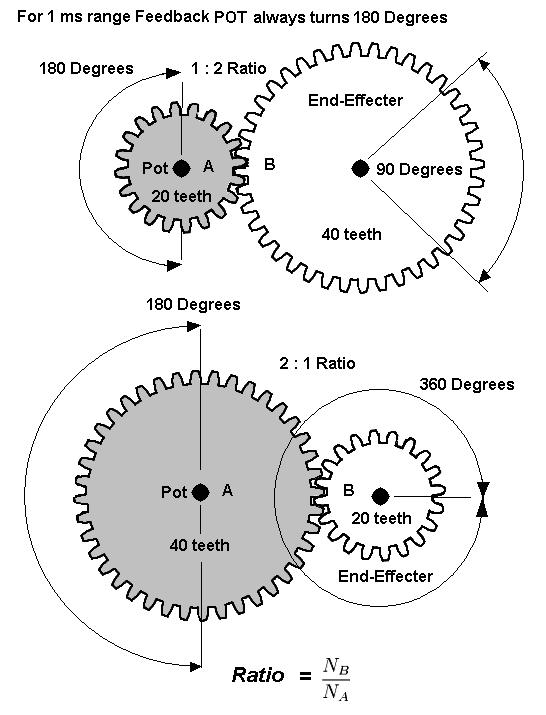
6 You also have to establish the degree of movement that your End-Effecter needs. The End- Effecter is the part of your design that does the actual work, either an arm, a pulley or a linear motion shaft. It is this Travel Range of the End-Effecter you must establish first. It is the ratio between your Feedback POT and your End-Effecter we need to calculate. Your Feedback POT represents a Fixed Parameter. A 1 ms Pulse Range will turn the POT 180 Degrees regardless of where your End-Effecter is positioned. Therefore you have to establish the gearing ratio between your End-Effecter and the Feedback POT. The degree of movement of the End-Effecter is used for the calculation. Controlling your End Effecter If you are making a Robot Arm and you attach the Feedback POT directly to the rotation axis of your arm without any gears, then your arm will have a 180 degree travel. Remember, the POT will always turn 180 degrees. If you want an arm to travel 90 Degrees, then you must use 2 Gear Wheels with a 1:2 Ratio. From the examples below, you should be able to calculate the gear ratio you need for your project. The actual number of gear teeth in the gears is not critical, only the teeth ratio between the POT gear and the END-EFFECTER is important. The END-EFFECTER is the last wheel or linkage in your design that does the actual work.
7
8 How to mount the Feedback Potentiometer. From experience, we strongly recommend NOT to mount the Feedback POT rigidly in a fixed position. Reason 1: If you accidentally reverse the plug to the Feedback POT into the controller, the end effecter will run past the POT limit and likely damage it. If you use this spring pulling system, the gear will simply slip and cause no damage to the POT. Reason 2: To set your end effecter to a physical position in relation to your joy stick or other controller, you don t have to loosen any screws. Simply pull the lever back and align the POT gear wheel to a different teeth position on the end effecter gear.
9 Programming the Tri-Mode Controller Has The 13 parameters are saved in non-volatile memory and take effect next time you power-up the controller. Before you start making changes, look at the setting choices below. The 13 Program selections =============================================================== 1. Mode 1 RC Power Servo 2. Mode 2 RC Speed Controller (Linear Table Only) 3. Mode 3 Manual Speed Controller (Linear Table Only) Ramp Delay = 16 Steps 5. Ramp Delay = 8 Steps 6. Ramp Delay = 6 Steps 7. Ramp Delay = 4 Steps 8. Ramp Delay = 0 = OFF Default Slope Table =1 Long decay 10 Slope Table =2 Linear Decay Default 11 Slope Table =3 Short Decay RC Pulse checking ON 13 RC Pulse checking OFF Default As you may notice, the program choices are numbered and are in groups. You can only select or change one parameter in each group. You can select 1 of the 3 Mode choices Settings for Mode Selection : Mode1: A Servo Mode. The RC pulse sets the position of an arm, wheel or other mechanical device. The potentiometer is attached to your end-effecter and is used to measure the IS NOW position and then tells the motor to turn in the proper direction and stop at that position. The POT must have a mechanical coupling to your end-effecter, either direct or via gears. This Mode only works if there is a RC Pulse detected within 250ms after power-up. If the RC Pulse is absent on power-up, the Mode will then default to Mode3 2: Mode2: A Speed Mode. On power-up, when the controller detects an RC Pulse and the controller is programmed for Mode2. The potentiometer is NOT attached to your end-effecter The RC Pulse is now used to control the speed and direction of your motor, The controller will now act as a Bidirectional Speed Controller. The POT is used as a fine trim to stop the motor when your RC joystick is in the center position. This Mode only works if there is a RC Pulse detected within 250ms after power-up. If the RC Pulse is absent on power-up, the Mode will then default to Mode3 3: Mode3: A Speed Mode. The controller will now act as a Bidirectional Motor Speed Controller. The potentiometer is NOT attached to your end-effecter. This Mode is also the default if there is NO RC Pulse detected within 250ms after power-up. The POT is now used to control the speed and direction of your motor. The motor will stop running when the POT is in center position and increase speed when the POT is turned away from center position.

10 5 Settings for Reverse-Protection Feature: Ramp Delay We also have to prevent the motor from instantaneously reversing direction. When the motor runs at full speed in the forward direction and we tell it to go to a position in the opposite direction, we must first slow the motor down. Only when the servo motor comes to a stop can we reverse direction and process the Up-Slope. This is necessary to allow robots to move fluidly and avoid stress or damage to gears, levers and pulleys. For some applications, like power steering, these features are not wanted or not necessary. Settings #4 to #7 lets you set the number of Slope Steps that effect the reversal protection. The #8 setting turns this feature Off and is the default setting. If you like to test this feature start with # Program Parameters for Motor Reversal Steps : Both Velocity Slopes, up and down, have 16 steps. This produces the longest slope. Usage: Very slow moving arms, servos that have lots of torque and lift heavy weights. 5: Both Velocity Slopes, up and down, have 8 steps. Slope count is divided by 2. Usage: Same as above but with high torque gearing. 6: Both Velocity Slopes, up and down, have 6 steps. Slope count is divided by 3.. Usage: For medium speed servos. 7: Both Velocity Slopes, up and down, have 4 steps. Slope count is divided by 4. This is the shortest slope but still useful. Usage: use if the servo starts to have signs of overshooting. 8: Both Velocity Slopes, up and down, are completely disabled. Default Setting Usage: For fast moving servos with low torque. Use if any of the above settings still cause overshooting the target position. Also best when instant response is needed like for a steering servo.
11 3 Settings for Speed Slope Selection Using more powerful motors necessitates the use of velocity ramping. If we were to apply full power to our Servo Motor that has a 1 or 2 pounds of lift load, we would first get a very jerky motion, and second, our hardware may not survive the stress of this instantaneous force. To bring a large weight into motion, we must match motor torque to weight load. Our RC Power Servo Controller will do this by slowly increasing the speed of the motor, which is known as Up-Ramping or Soft-Start, and do the same to slow it down by Down-Ramping.. Basically we need to control the Speed when we want to go from one servo position to another. Not all Servo Applications are equal. Some are for moving large weights, torque being the main criteria. Others are for quick responding applications like Power Steering, Velocity being the main criteria. If your end-effecter arm takes less than 3 seconds for a 180 degree turn, then the feedback signal is faster than what we can process and your effecter arm would overshoot the target position. For this reason, we have to slow our motor down before we reach the target position. For fast moving servos we need to use a quick decaying slope to prevent the servo from overshooting the target position. Use program #9 for this purpose. The #10 slope is the default setting and will work for most applications. For slow and very slow servos use #11 setting. 3 Program Parameters for Slope Selection Slope Type Usage 9: Fast Decay for fast moving servos, like a steering servo. 10: Linear Slope for medium speed servos. Default Setting 11: Slow Decay for slow moving servos. 2 Settings for Start Up Safety Protection: In order to prevents your robotics going a mock and cause serious damage, we need a Start Up Safety Protection that will not arm the motor until it receives at least one valid RC Pulse of 1.5 ms. This prevents your Robotics from moving randomly and cause serious damage. This can occur if you apply Motor Power before you activate your RC Controller. Your Joystick or the POT, depending on the application, has to be in the center position to enable the motor to turn. When this feature is enabled, you have to move your controller to the center OFF position before the Motor gets power Settings for Power-Up safe start feature. 1.5ms Rc Pulse detection : 1.5ms pulse detection = ON 13: 1.5ms pulse detection = OFF Default Setting
12 Programming Instructions for the Tri-mode Controller And finally, a simple programmer you have to build yourself. You only need 1 single pole switch and 1 normally open pushbutton to program any of the 13 settings. Before you start any programming activity, please do the following. Disconnect the Power Source for the Motor. This is for safety reasons. Your motor could start turning when you disconnect the Feedback Potentiometer. Disconnect the Feedback-Potentiometer Remove the 3 pin plug that comes from your RC-Controller Board or RC Radio Receiver or other power source for the Micro-Controller Connect the Programmer circuit as shown above. This must be done when the controller has NO power. Now you can program any of the 13 settings 1.) Close the Toggle Switch. When the controller detects that this pin is on ground when you apply power and it boots, it goes into programming mode. 2.) Connect the power source, 5 to 6 volts. Now in programming mode. 3.) Now press the Pushbutton the number of times that matches the parameter you like to set. The maximum # is 13 4.) When you have completed pressing the button X times, Open the Toggle Switch. The Micro-Controller will now safe your Setting in Flash-Memory. This must be done before you disconnect the power. 5.) You must now disconnect the power, the cable that comes from your RC Controller or RC Radio. Your controller is now programmed to a new setting. 6.) To change another setting, go to step # 1.
13 Here is a summary of the programming sequence : Disconnect the Motor Power and follow these steps in sequence Disconnect the 5-6 volt Controller Power Connect Switch and Button AA Close Toggle Switch Apply the 5-6 volt Power now in program mode Push button as many times as the Setting number Open Toggle Switch now in save setting mode Disconnect the 5-6 volt Power To program more settings -- go to AA To test your new setting, re-connect your motor and your feedback potentiometer and the power source for the motor, and last the cable to your RC Controller or RC Radio. Be careful when trying out your new settings. Unexpected results may appear. We like to thank you for purchasing this product. Please report any errors you may find. We are also open to suggestions to make this a better product. You can contact support@rcpowerservo.com
TOP SERVO SIGNAL 5 SERVO SIGNAL 3 SERVO SIGNAL 4 SERVO SIGNAL 6 T B T B T B T B T B SERVO TRIGGER 1 BOTTOM
 Micro Miniatures Servo Controller Channel Location of connections and switches TOP SERVO SIGNAL SERVO SIGNAL 7 SERVO SIGNAL 6 SERVO SIGNAL 5 SERVO SIGNAL SERVO SIGNAL SERVO SIGNAL SERVO SIGNAL SIGNAL COMMON
HB-25 Motor Controller (#29144)
") Web Site: www.parallax.com Forums: forums.parallax.com Sales: sales@parallax.com Technical: support@parallax.com Office: (916) 624-8333 Fax: (916) 624-8003 Sales: (888) 512-1024 Tech Support: (888) 997-8267
Web Site: www.parallax.com Forums: forums.parallax.com Sales: sales@parallax.com Technical: support@parallax.com Office: (916) 624-8333 Fax: (916) 624-8003 Sales: (888) 512-1024 Tech Support: (888) 997-8267
40 Amp Digital Bidirectional PWM Motor Controller with Regenerative Braking BIDIR-340-DR
 40 Amp Digital Bidirectional PWM Motor Controller with Regenerative Braking BIDIR-340-DR The BIDIR-340-DR is a fully solid-state motor controller that allows you to control the speed and direction of a
10 Amp Digital PWM Motor Speed Controller CV-2110-HD and CV-2110-HDS
 10 Amp Digital PWM Motor Speed Controller CV-2110-HD and CV-2110-HDS The Analog / Digital PWM controller allows you to control the speed of a motor, brightness of a lamp or other device using an analog
DLVP A OPERATOR S MANUAL
 DLVP-50-300-3000A OPERATOR S MANUAL DYNALOAD DIVISION 36 NEWBURGH RD. HACKETTSTOWN, NJ 07840 PHONE (908) 850-5088 FAX (908) 908-0679 TABLE OF CONTENTS INTRODUCTION...3 SPECIFICATIONS...5 MODE SELECTOR
Jaguar Motor Controller (Stellaris Brushed DC Motor Control Module with CAN)
") Jaguar Motor Controller (Stellaris Brushed DC Motor Control Module with CAN) 217-3367 Ordering Information Product Number Description 217-3367 Stellaris Brushed DC Motor Control Module with CAN (217-3367)
Jaguar Motor Controller (Stellaris Brushed DC Motor Control Module with CAN) 217-3367 Ordering Information Product Number Description 217-3367 Stellaris Brushed DC Motor Control Module with CAN (217-3367)
Hobby Servo Tutorial. Introduction. Sparkfun: https://learn.sparkfun.com/tutorials/hobby-servo-tutorial
 Hobby Servo Tutorial Sparkfun: https://learn.sparkfun.com/tutorials/hobby-servo-tutorial Introduction Servo motors are an easy way to add motion to your electronics projects. Originally used in remotecontrolled
User guide. Revision 1 January MegaPoints Controllers
 MegaPoints Servo 4R Controller A flexible and modular device for controlling model railway points and semaphore signals using inexpensive R/C servos and relays. User guide Revision 1 January 2018 MegaPoints
MegaPoints Controller
 MegaPoints Controller A flexible solution and modular component for controlling model railway points and semaphore signals using inexpensive servos. User guide Revision 10c March 2015 MegaPoints Controllers
15 Amp Digital High Frequency PWM Motor Speed Controller SPD-315-D and SPD-315-DS
 15 Amp Digital High Frequency PWM Motor Speed Controller SPD-315-D and SPD-315-DS The SPD-315-D(S) PWM controller allows you to control the speed of a motor, brightness of a lamp or other load using a
DynaDrive INFORMATION MANUAL SDFP(S)
") DynaDrive INFORMATION MANUAL SDFP(S)1525-17 SERVO DYNAMICS CORP. 28231 Avenue Crocker, Santa Clarita, CA. 91355 (818) 700-8600 Fax (818) 718-6719 www.servodynamics.com INDEX Page INTRODUCTION 2 ELECTRICAL
DynaDrive INFORMATION MANUAL SDFP(S)1525-17 SERVO DYNAMICS CORP. 28231 Avenue Crocker, Santa Clarita, CA. 91355 (818) 700-8600 Fax (818) 718-6719 www.servodynamics.com INDEX Page INTRODUCTION 2 ELECTRICAL
RC Camera Control. User Guide v1.3 (RCCC v1.1) 11/7/2012
 11/7/2012") RC Camera Control User Guide v1.3 (RCCC v1.1) 11/7/2012 kristaps_r@rcgroups INTRODUCTION RC Camera Control board (RCCC) is multifunctional control board designed to for aerial photography or First Person
RC Camera Control User Guide v1.3 (RCCC v1.1) 11/7/2012 kristaps_r@rcgroups INTRODUCTION RC Camera Control board (RCCC) is multifunctional control board designed to for aerial photography or First Person
Series 70 Servo NXT - Modulating Controller Installation, Operation and Maintenance Manual
 THE HIGH PERFORMANCE COMPANY Series 70 Hold 1 sec. Hold 1 sec. FOR MORE INFORMATION ON THIS PRODUCT AND OTHER BRAY PRODUCTS PLEASE VISIT OUR WEBSITE www.bray.com Table of Contents 1. Definition of Terms.........................................2
SRVODRV REV7 INSTALLATION NOTES
 SRVODRV-8020 -REV7 INSTALLATION NOTES Thank you for purchasing the SRVODRV -8020 drive. The SRVODRV -8020 DC servo drive is warranted to be free of manufacturing defects for 1 year from the date of purchase.
Autonomous Robot Control Circuit
 Autonomous Robot Control Circuit - Theory of Operation - Written by: Colin Mantay Revision 1.07-06-04 Copyright 2004 by Colin Mantay No part of this document may be copied, reproduced, stored electronically,
Brushed DC Motor Control. Module with CAN (MDL-BDC24)
") Stellaris Brushed DC Motor Control Module with CAN (MDL-BDC24) Ordering Information Product No. MDL-BDC24 RDK-BDC24 Description Stellaris Brushed DC Motor Control Module with CAN (MDL-BDC24) for Single-Unit
Stellaris Brushed DC Motor Control Module with CAN (MDL-BDC24) Ordering Information Product No. MDL-BDC24 RDK-BDC24 Description Stellaris Brushed DC Motor Control Module with CAN (MDL-BDC24) for Single-Unit
1525-BRS INFORMATION MANUAL SERV O D YN A M ICS. D y n ad r iv e Ave Crocker Suite 10 Valencia, CA
 28231 Ave Crocker Suite 10 Valencia, CA 91355 818-700-8600 Servodynamics.com INFORMATION MANUAL 1525-BRS SERV O D YN A M ICS U SA www.servodynamics.com D y n ad r iv e Bru sh INDEX Page INTRODUCTION 2
DeviceCraft Revision #1 11/29/2010
 DeviceCraft Revision #1 11/29/2010 DC Wiper Motor H-Bridge Servo / Speed Controller P/N 1020 Features: Dip Switch selectable mode of operation Both PID servo or speed controller Forward/Reverse operation
PS2-SMC-06 Servo Motor Controller Interface
 PS2-SMC-06 Servo Motor Controller Interface PS2-SMC-06 Full Board Version PS2 (Playstation 2 Controller/ Dual Shock 2) Servo Motor Controller handles 6 servos. Connect 1 to 6 Servos to Servo Ports and
815-BR SERVO AMPLIFIER FOR BRUSH SERVOMOTORS
 815-BR SERVO AMPLIFIER FOR BRUSH SERVOMOTORS USER GUIDE September 2004 Important Notice This document is subject to the following conditions and restrictions: This document contains proprietary information
MAE106 Laboratory Exercises Lab # 3 Open-loop control of a DC motor
 MAE106 Laboratory Exercises Lab # 3 Open-loop control of a DC motor University of California, Irvine Department of Mechanical and Aerospace Engineering Goals To understand and gain insight about how a
BLD75-1. Bilevel Step Motor Driver. User s Guide. #L010125
 BLD75-1 Bilevel Step Motor Driver User s Guide A N A H E I M A U T O M A T I O N #L010125 1 Features Unipolar Operation 10 Amps per Phase Operating Current (Kick Current) 7 Amps per Phase Standstill Current
Analog Servo Drive. Peak Current 16 A (11.3 A RMS )
") Description The PWM servo drive is designed to drive three phase brushless motors with sine wave current at a high switching frequency. The drive requires two sinusoidal command signals with a 120-degree
Description The PWM servo drive is designed to drive three phase brushless motors with sine wave current at a high switching frequency. The drive requires two sinusoidal command signals with a 120-degree
MegaPoints Servo Controller
 MegaPoints Servo Controller Covers Servo Controller boards 1.8 onwards A flexible and modular device for controlling model railway points and semaphore signals using inexpensive R/C servos and relays.
Directions for Wiring and Using The GEARS II (2) Channel Combination Controllers
 Channel Combination Controllers") Directions for Wiring and Using The GEARS II (2) Channel Combination Controllers PWM Input Signal Cable for the Valve Controller Plugs into the RC Receiver or Microprocessor Signal line. White = PWM Input
Directions for Wiring and Using The GEARS II (2) Channel Combination Controllers PWM Input Signal Cable for the Valve Controller Plugs into the RC Receiver or Microprocessor Signal line. White = PWM Input
Servo Tuning Tutorial
 Servo Tuning Tutorial 1 Presentation Outline Introduction Servo system defined Why does a servo system need to be tuned Trajectory generator and velocity profiles The PID Filter Proportional gain Derivative
Blue Point Engineering
 Blue Point Engineering Instruction I www.bpesolutions.com Pointing the Way to Solutions! Puppet - II+ Controller (BPE No. PCA-0001) Servo Position Adjustment EEPROM Digital Button Power 5 Vdc Playback
Parts to be supplied by the student: Breadboard and wires IRLZ34N N-channel enhancement-mode power MOSFET transistor
 University of Utah Electrical & Computer Engineering Department ECE 1250 Lab 3 Electronic Speed Control and Pulse Width Modulation A. Stolp, 12/31/12 Rev. Objectives 1 Introduce the Oscilloscope and learn
Figure 1. DMC 60 components.
 1300 Henley Court Pullman, WA 99163 509.334.6306 www.digilentinc.com DMC 60 Reference Manual Revised November 15, 2016 This manual applies to the DMC 60 rev. A Overview The DMC 60 is an electronic speed
ELECTRICAL ENGINEERING TECHNOLOGY PROGRAM EET 433 CONTROL SYSTEMS ANALYSIS AND DESIGN LABORATORY EXPERIENCES
 ELECTRICAL ENGINEERING TECHNOLOGY PROGRAM EET 433 CONTROL SYSTEMS ANALYSIS AND DESIGN LABORATORY EXPERIENCES EXPERIMENT 4: ERROR SIGNAL CHARACTERIZATION In this laboratory experience we will use the two
BFS / BFSM SERIES Installation & Maintenance Manual
 Introduction: The BFS / BFSM series electric actuators have battery backup modules for fail safe operation. The BFS series is for two position control and the BFSM series is for proportional control, both
DPFHP451 HIGH PERFORMANCE BILEVEL STEP MOTOR / MANUAL PRESET INDEXER DRIVER PACK
 DPFHP451 HIGH PERFORMANCE BILEVEL STEP MOTOR / MANUAL PRESET INDEXER DRIVER PACK Internal Index Count switches Pulse Rates up to 14,792 pulses per second CW & CCW Home, Hard, & Soft Limit Inputs Adjustable
PEAKTRONICS AMC-103 ADDITIONAL FEATURES. AC Motor Controller, 2A AMC-103 AMC-103A AMC-103B
 PEAKTRONICS The Peaktronics AC Motor Controller is a compact module that is intended for controlling small AC actuator motors of up to 2A. The is very well suited for applications where space constraints
Tarocco Closed Loop Motor Controller
 Contents Safety Information... 3 Overview... 4 Features... 4 SoC for Closed Loop Control... 4 Gate Driver... 5 MOSFETs in H Bridge Configuration... 5 Device Characteristics... 6 Installation... 7 Motor
STPDRV-1 Stepper Motor Driver Data Sheet (R1.0) BFF Design Ltd
 BFF Design Ltd") STPDRV-1 Stepper Motor Driver Data Sheet (R1.0) BFF Design Ltd 1. Introduction The BFF STPDRV-1 card is a bi-polar stepper motor driver. It is designed to drive the BFF Motorised Trim Wheel or other user-designed
STPDRV-1 Stepper Motor Driver Data Sheet (R1.0) BFF Design Ltd 1. Introduction The BFF STPDRV-1 card is a bi-polar stepper motor driver. It is designed to drive the BFF Motorised Trim Wheel or other user-designed
Servos A Brief Guide
 Servos A Brief Guide David Sanderson, MEng (hons) DIS, CEng MIMarEST Technical Director at Kitronik Radio Control (RC) Servos are a simple way to provide electronically controlled movement for many projects.
StenBOT Robot Kit. Stensat Group LLC, Copyright 2018
 StenBOT Robot Kit 1 Stensat Group LLC, Copyright 2018 Legal Stuff Stensat Group LLC assumes no responsibility and/or liability for the use of the kit and documentation. There is a 90 day warranty for the
CX-1X Mini Heading-Hold Gyro System. Copyright 2014 KY MODEL Company Limited.
 CX-1X2000 Mini Heading-Hold Gyro System INSTRUCTION MANUAL www.copterx.com Copyright 2014 KY MODEL Company Limited. MENU 1. 2. 3. 4. 5. 6. 7. 8. 9. 10. Table of content Introduction Features Specifications
ECE 511: FINAL PROJECT REPORT GROUP 7 MSP430 TANK
 ECE 511: FINAL PROJECT REPORT GROUP 7 MSP430 TANK Team Members: Andrew Blanford Matthew Drummond Krishnaveni Das Dheeraj Reddy 1 Abstract: The goal of the project was to build an interactive and mobile
Contents. Warranty and Disclaimer 2 Introduction 3
 Contents Warranty and Disclaimer 2 Introduction 3 Physical Dimensions Board Layout 4 Servo connections 5 Using the Serv8 Usage 6 Setting the start address 7 Setting the pulse width 8 Using the configuration
Assembly Language. Topic 14 Motion Control. Stepper and Servo Motors
 Assembly Language Topic 14 Motion Control Stepper and Servo Motors Objectives To gain an understanding of the operation of a stepper motor To develop a means to control a stepper motor To gain an understanding
12V Victor 888 User Manual
 The Victor speed controllers are specifically engineered for robotic applications. The high current capacity, low voltage drop, and peak surge capacity make the Victor ideal for drive systems while its
Q181EB Expression Block Controller
 The controller produces a voltage as you press the block, similar to the Ondes Martenot and other instruments. Perfect for controlling amplitude as you play notes on the keyboard, to control filter frequency,
Q181V Whammy Bar Controller
 This document covers our Whammy Bar controllers in these configurations: Q181V1 Single-axis Whammy Bar in a single-channel Q181 panel Q181V1 Whammy Bar Q182V2 Dual-axis Whammy Bar in a dual-channel Q182
Converting a Hobby Servomotor to a DC Gearhead Motor
 Converting a Hobby Servomotor to a DC Gearhead Motor Ted Pavlic December 15, 2004 Summary While there are many resources that provide instruction for modifying a hobby servomotor for continuous rotation,
Budget Robotics Octabot Assembly Instructions
 Budget Robotics Octabot Assembly Instructions The Budget Robotics Octabot kit is a low-cost 7" diameter servo-driven robot base, ready for expansion. Assembly is simple, and takes less than 15 minutes.
Ocean Controls KT-5198 Dual Bidirectional DC Motor Speed Controller
 Ocean Controls KT-5198 Dual Bidirectional DC Motor Speed Controller Microcontroller Based Controls 2 DC Motors 0-5V Analog, 1-2mS pulse or Serial Inputs for Motor Speed 10KHz, 1.25KHz or 156Hz selectable
µservo drive user s guide
 µservo drive user s guide Features: Precise positioning with adjustable PID filter. Closed loop operation with incremental encoder feedback. Short circuit protection. Overtemperature protection. Fixed
SCS Automation and Control Ltd
 1 SCS Automation and Control Ltd Dead band / Camera Position controller SCS Automation and Control Ltd Automation Centre 156 Stanley Green Road Poole Dorset England BH15 3AH 2 1) INTRODUCTION ATTENTION
Operator s Manual Ride-On Remote Controlled Car
 Operator s Manual Ride-On Remote Controlled Car By Kevin Franzino Kelly O Neill Jeffrey Peterson Project for Client #14: Samantha Gillard Client Contacts: Geoff and Jenny Gillard: Newton, MA 617 447-0783;
Blue Point Engineering
 Blue Point Engineering Instruction I www.bpesolutions.com Pointing the Way to Solutions! Animatronic Wizard - 3 Board (BPE No. WAC-0030) Version 3.0 2009 Controller Page 1 The Wizard 3 Board will record
ZT-30 ZeroTEM TRANSMITTER MANUAL
 ZT-30 ZeroTEM TRANSMITTER MANUAL 06 September, 2000 Zonge Engineering and Research Organization, Inc. 3322 East Fort Lowell Road, Tucson, AZ 85716 USA Tel:(520)327-5501 Fax:(520)325-1588 Email:zonge@zonge.com
CONSTRUCTION GUIDE Robotic Arm. Robobox. Level II
 CONSTRUCTION GUIDE Robotic Arm Robobox Level II Robotic Arm This month s robot is a robotic arm with two degrees of freedom that will teach you how to use motors. You will then be able to move the arm
12V Dimmer Kit, version 2
 12V Dimmer Kit, version 2 User Manual Description The 12V Dimmer Kit V2 is an especially efficient PWM (pulse-width modulation) controller for 12V loads up to 60 watts. It features a single dial control
Convert a Hitec HS-300 Servo to Continuous Operation
 Site Map Shopping Cart Engineering Services Contact US Home Dios and Athena KRMx01 Mechanics Projects Downloads Forums GAN116_hs300 Convert a Hitec HS-300 Servo to Continuous Operation By Michael Simpson
Jet Central Sequencer Plus
 Jet Central Sequencer Plus Features The Jet Central Sequencer Plus is a multipurpose electronic device, the capabilities of the unit include: Three part sequencer, operating landing gear and two independent
Digital Interface Card DEC005000
 Engineering & Manufacturing Solutions Digital Interface Card DEC005000 APPLICATION: The DEC005000 conveniently interfaces industry standard signals 4-20mA, 0-5V or 0-10V with a proportional solenoid valve
C41 VARIABLE SPEED CONTROL Rev. 1.1
 C41 VARIABLE SPEED CONTROL Rev. 1.1 User manual Rev.1 1. Overview This card lets you control your spindle with PWM and direction signals, as if it was an axis motor. It converts the step signal into and
Project Name: SpyBot
 EEL 4924 Electrical Engineering Design (Senior Design) Final Report April 23, 2013 Project Name: SpyBot Team Members: Name: Josh Kurland Name: Parker Karaus Email: joshkrlnd@gmail.com Email: pbkaraus@ufl.edu
Milliamp Calibrator. Model 434. General description. Calibrate with laboratory accuracy. All 4 to 20 ma loop functions
 Milliamp Calibrator Model 434 General description Calibrate Loop Instruments Calibrate and troubleshoot all the signals in a standard 4 to 20 milliamp process control loop with Altek s Model 434 Milliamp
Independent Technology Service Inc Independence Ave. Chatsworth, California Toll Free:
 Independent Technology Service Inc. 9182 Independence Ave. Chatsworth, California 91311 www.itscnc.com Toll Free: 1.800.342.3475 NEW Brush Amplifiers For Fadal Machines AMP-0006N-ITS AMP-0021N-ITS NEW
RC-WIFI CONTROLLER USER MANUAL
 RC-WIFI CONTROLLER USER MANUAL In the rapidly growing Internet of Things (IoT), applications from personal electronics to industrial machines and sensors are getting wirelessly connected to the Internet.
Parts List. Robotic Arm segments ¼ inch screws Cable XBEE module or Wifi module
 Robotic Arm 1 Legal Stuff Stensat Group LLC assumes no responsibility and/or liability for the use of the kit and documentation. There is a 90 day warranty for the Sten-Bot kit against component defects.
DR3535 DR3535-O. Hardware Reference Manual. Document Revision A7 May 16, 2018 MICROKINETICS CORPORATION
 -O Hardware Reference Manual Document Revision A7 May 16, 2018 MICROKINETICS CORPORATION 3380 Town Point Drive Suite 330 Kennesaw, GA 30144 Tel: (770) 422-7845 Fax: (770) 422-7854 www.microkinetics.com
Ametek, Inc. Rotron Technical Products Division. 100 East Erie St., Suite 200 Kent, Ohio User's Guide. Number Revision F
 Ametek, Inc. Rotron Technical Products Division 100 East Erie St., Suite 200 Kent, Ohio 44240 User's 120 Volt, 800 Watt and 240 Volt, 1200 Watt Brushless Motor Drive Electronics 5.7" (145 mm) and 7.2"
HM4050 AVCS HEADING LOCK GYRO
 INCLUDES HM4050 gyro with connectors Foam adhesive tape Manual HM4050 AVCS HEADING LOCK GYRO FEATURES AVCS (Angular Vector Control System) Small size Lightweight Able to operate in Heading Hold as well
Dimensions: Specifications:
 Rover 5 Rover 5 is a new breed of tracked robot chassis designed specifically for students and hobbyist. Unlike conventional tracked chassis s the clearance can be adjusted by rotating the gearboxes in
Mounting Dimensions. Overview. Installation. Specifications
 Overview Mounting Dimensions RageBridge 2 is a motor controller that can drive 2 channels of DC motors, using several types of inputs, in forward and reverse with no delay. It features signal-loss failsafes,
Bill of Materials: PWM Stepper Motor Driver PART NO
 PWM Stepper Motor Driver PART NO. 2183816 Control a stepper motor using this circuit and a servo PWM signal from an R/C controller, arduino, or microcontroller. Onboard circuitry limits winding current,
The Allen-Bradley Servo Interface Module (Cat. No SF1) when used with the Micro Controller (Cat. No UC1) can control single axis
 when used with the Micro Controller (Cat. No UC1) can control single axis") Table of Contents The Allen-Bradley Servo Interface Module (Cat. No. 1771-SF1) when used with the Micro Controller (Cat. No. 1771-UC1) can control single axis positioning systems such as found in machine
Table of Contents The Allen-Bradley Servo Interface Module (Cat. No. 1771-SF1) when used with the Micro Controller (Cat. No. 1771-UC1) can control single axis positioning systems such as found in machine
Silencer Series Brushless Controllers
 Silencer Series Brushless Controllers BDP-Q2-50-10, BDP-Q2-20-10 2-quadrant speed controller for brushless motors GENERAL Instruction Manual The BDP-Q2-50-10, BDP-Q2-20-10 controllers are 2-quadrant speed
Analog Servo Drive 20A20
 Description Power Range NOTE: This product has been replaced by the AxCent family of servo drives. Please visit our website at www.a-m-c.com or contact us for replacement model information and retrofit
Your Global Flow Control Partner. Series 70 SERVO PRO Version 3.0 Operation and Maintenance Manual
 Your Global Flow Control Partner Series 70 SERVO PRO Version 3.0 Table of Contents 1.0 Safety Instructions - Definition of Terms...........................2 1.1 Hazard-free Use.......................................2
7I54 MANUAL Six channel 40V 3A Servo motor drive
 7I54 MANUAL Six channel 40V 3A Servo motor drive V1.1 This page intentionally almost blank Table of Contents GENERAL.......................................................... 1 DESCRIPTION.................................................
Analog Servo Drive. Continuous Current. Features
 Description Power Range The PWM servo drive is designed to drive three phase brushless motors with sine wave current at a high switching frequency. The drive requires two sinusoidal command signals with
ME 461 Laboratory #5 Characterization and Control of PMDC Motors
 ME 461 Laboratory #5 Characterization and Control of PMDC Motors Goals: 1. Build an op-amp circuit and use it to scale and shift an analog voltage. 2. Calibrate a tachometer and use it to determine motor
Post-Installation Checkout All GRT EFIS Models
 GRT Autopilot Post-Installation Checkout All GRT EFIS Models April 2011 Grand Rapids Technologies, Inc. 3133 Madison Avenue SE Wyoming MI 49548 616-245-7700 www.grtavionics.com Intentionally Left Blank
Analog Servo Drive 25A20DD
 Description Power Range NOTE: This product has been replaced by the AxCent family of servo drives. Please visit our website at www.a-m-c.com or contact us for replacement model information and retrofit
Testra Corporation ss483 Series Microstepping Motor Driver. Specifications Sep SoftStep FIRMWARE FEATURES
 SoftStep The New Art of Stepper Motor Control With SoftStep you get the benefits of ultra smooth microstepping regardless of your selected step size. The intelligent on board processor treats the input
Sealed Interface Control: EC20300
 ISO 9001:2000 WITH DESIGN Certificate #02.002.1 Sealed Interface Control: EC20300 FEATURES: Weather tight control package Pulse Width Modulated output Waterproof altitude pressure and vapor release vent
TEAM DIGITAL. SMC4 Servo & Motor Controller
 16 CV# Function/Default Value CV# Function/Default Value 28 reserved - 73 Servo 3 Behavior 0 29 Decoder Configuration 0 74 Servo 4 Behavior 0 30 reserved - 75 Output Flash 0 31 Ops Mode Loco Address 1
SERIES 70. R SERVO PRO Version 3.0 OPERATION AND MAINTENANCE MANUAL. The High Performance Company
 SERIES 70 R SERVO PRO Version 3.0 OPERATION AND MAINTENANCE MANUAL The High Performance Company Contents 1.0 Safety Instructions - Definition of Terms 2 1.1 Hazard-free Use 2 1.2 Qualified Personnel 2
A3 Pro INSTRUCTION MANUAL. Oct 25, 2017 Revision IMPORTANT NOTES
 A3 Pro INSTRUCTION MANUAL Oct 25, 2017 Revision IMPORTANT NOTES 1. Radio controlled (R/C) models are not toys! The propellers rotate at high speed and pose potential risk. They may cause severe injury
C-COM Satellite Systems Inc. Page 1 of 39
 Page 1 of 39 inetvu Fly-75V & Fly-98G/H/V & Fly-981 User Manual The inetvu brand and logo are registered trademarks of C-COM Satellite Systems, Inc. Copyright 2006 C-COM Satellite Systems, Inc. 1-877-iNetVu6
1250 Automatic Traverse
 Adams-Maxwell Winding Systems Operating Manual 1250 Automatic Traverse Adams-Maxwell Winding Systems Page 2 Adams-Maxwell 4740 Calle Carga Camarillo, CA 93012 Phone: (323) 936-8028 Fax: (888) 936-8042
1260 Automatic Traverse
 Adams-Maxwell Winding Systems Operating Manual 1260 Automatic Traverse Page 2 Adams-Maxwell 4740 Calle Carga Camarillo, CA 93012 Phone: (323) 936-8028 Fax: (888) 936-8042 Web: www.adamsmaxwell.com Email:
Name & SID 1 : Name & SID 2:
 EE40 Final Project-1 Smart Car Name & SID 1 : Name & SID 2: Introduction The final project is to create an intelligent vehicle, better known as a robot. You will be provided with a chassis(motorized base),
Operation and Installation Manual
 The Next Generation of Operation and Installation Manual G-Scale Graphics 5860 Crooked Stick Dr. Windsor, CO 80550 970-581-3567 GScaleGraphics@comcast.net www.gscalegraphics.net Revision C: H: Updated
MicroManager. Velocity Mode PID Dancer/Loadcell Control. Instruction Manual MM3000-PID
 MicroManager Velocity Mode PID Dancer/Loadcell Control Instruction Manual MM3000-PID Table of Contents 1. General Description... 5 2. Specifications... 5 2.1 Electrical... 5 2.2 Physical... 6 3. Installation...
AMERITRON SDC-102 Screwdriver Antenna Controller
 AMERITRON SDC-102 Screwdriver Antenna Controller INSTRUCTION MANUAL PLEA S E REA D T H IS M A NU A L BEFORE OP ERA T I N G T H IS EQU IP M EN T! 116 Willow Road Starkville, MS 39759 USA 662-323-8211 Version
Motomatic Servo Control
 Exercise 2 Motomatic Servo Control This exercise will take two weeks. You will work in teams of two. 2.0 Prelab Read through this exercise in the lab manual. Using Appendix B as a reference, create a block
AMC-100 AMC-101 AMC-100 AMC-100B AMC-100D AMC-101 AMC-101B AMC-101D AMC-100A AMC-100C AMC-100E AMC-101A AMC-101C AMC-101E. AC Motor Controllers
 The Indelac / AC Motor Controllers are used for proportional positioning of split phase AC actuator motors. An external command signal of 0-0V, -V, or -0mA can be used to compare to a feedback signal from
DM8010 tm. Hardware Reference Manual. Document Revision B3 May 16, 2018
 tm Hardware Reference Manual Document Revision B3 May 16, 2018 MICROKINETICS CORPORATION 3380 Town Point Drive Suite 330 Kennesaw, Georgia 30144 Tel: (770) 422-7845 Fax: (770) 422-7854 Table Of Contents
ServoDMX OPERATING MANUAL. Check your firmware version. This manual will always refer to the most recent version.
 ServoDMX OPERATING MANUAL Check your firmware version. This manual will always refer to the most recent version. WORK IN PROGRESS DO NOT PRINT We ll be adding to this over the next few days www.frightideas.com
Installation & Operating Instructions
 FX (513) 4895243 Installation & Operating Instructions utomax electric actuators with servo control are factory adjusted for 90 degree operation and shipped in the full clockwise position as viewed from
ECE 203 LAB 6: INVERTED PENDULUM
 Version 1.1 1 of 15 BEFORE YOU BEGIN EXPECTED KNOWLEDGE Basic Circuit Analysis EQUIPMENT AFG Oscilloscope Programmable Power Supply MATERIALS Three 741 Opamps TIP41 NPN power transistor TIP42 PNP power
RB-Rop-08 Scorpion XXL Dual 20A 6V to 28V R/C DC Motor Driver
 RB-Rop-08 Scorpion XXL Dual 20A 6V to 28V R/C DC Motor Driver The Robot Power Scorpion XXL is a flexible high-performance two-channel motor controller for small to medium mobile robots such as firefighting
Studuino Icon Programming Environment Guide
 Studuino Icon Programming Environment Guide Ver 0.9.6 4/17/2014 This manual introduces the Studuino Software environment. As the Studuino programming environment develops, these instructions may be edited
LAB 1 AN EXAMPLE MECHATRONIC SYSTEM: THE FURBY
 LAB 1 AN EXAMPLE MECHATRONIC SYSTEM: THE FURBY Objectives Preparation Tools To see the inner workings of a commercial mechatronic system and to construct a simple manual motor speed controller and current
Bi-Directional DC Motor Speed Controller 5-32Vdc (3166v2)
") General Guidelines for Electronic Kits and Assembled Modules Thank you for choosing one of our products. Please take some time to carefully read the important information below concerning use of this product.
General Guidelines for Electronic Kits and Assembled Modules Thank you for choosing one of our products. Please take some time to carefully read the important information below concerning use of this product.