T5x Error Codes DGC5X Console Board W/ ACD3X LCB
|
|
|
- Leslie Hunt
- 6 years ago
- Views:
Transcription
1 Rev 2 4/18/06 T5x Error Codes DGC5X Console Board W/ ACD3X LCB Table of Contents Page # Error Code Description 2 Service Information 2-3 Serial Number Information 2 Manager Mode & Engineering Mode 2 Service 5 Mode Details 2-3 Elevation Movement Related Errors 4-12 E1 Reverse Elevation Pot 5-6 E1 Corrective Action Parts Needed 7 E2 Elevation Out of Range 8-9 E2 Corrective Action Parts Needed 10 E3 Elevation Stall 11 E3 Corrective Action Parts Needed 12 Speed Movement Related Errors E5 Over Speed 14 E5 Corrective Action Parts Needed 15 E6 Runaway Belt 16 E6 Corrective Action Parts Needed 17 E7 Speed Sensor Feedback Missing 18 E7 Corrective Action Parts Needed 19 E9 Speed Range 20 E9 Corrective Action Parts Needed 21 Speed Feedback Issue Corrective Action 22 Speed Feedback Issue Corrective Action Parts Needed 23 Operational Errors E16 Stuck Key Pad 25 E16 Corrective Action Parts Needed 25 E18 Safety Switch Test Failure 26 E18 Corrective Action Parts Needed 27 E19 NOVRAM Failure 28 E19 Corrective Action Parts Needed 28 LCB DFR Error Log E40 Registered error code sent from the motor control board ACD3X LCB Blink LED Error Codes T5x Error Codes DGC5X Console Board W / ACD3X LCB 1
2 Notes: If there are any safety concernes please call the Matrix Fitness Systems Service Department at before performing any service. Please make sure to take any saftey percautions before performing any service. Unplug any electrical power cords before touching any electrical components. Use common sense before performing any electrical service. Do not touch any component that is hot or looks to be hot. ERROR CODES Errors are divided in elevation related errors (E1 E3),speed related errors (E5 E9) or Operation Errors (E16-E19), LCB DFR Errors (E40) System should be properly calibrated (if possible) before attempting to troubleshoot error codes. The following table contains standard error codes. Other error codes are enabled for development purposes but cannot be remedied via engineering variables. Error codes above 9 require toggle of system power to reset. Error codes 9 and below can be remedied in some conditions by system calibration. CODE DESCRIPTION 1 Reverse Elevation Pot 2 Elevation Out Of Range 3 Elevation Movement Stall 5 Over-Speed 6 Runaway Belt 7 Speed Sensor Feedback Missing 9 Speed Range (usually caused by calibration) 16 Stuck Key Error 18 Safety Switch Test Failure 19 NOVRAM Failure 40 Drive Fault Error T5x Error Codes DGC5X Console Board W / ACD3X LCB 2
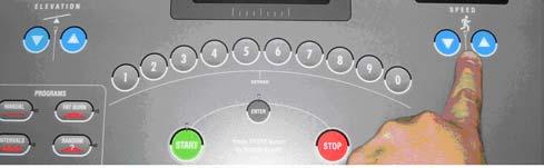
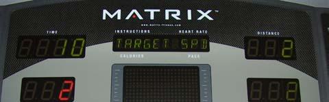
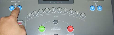
3 Service Information For faster service please have the following information ready. Serial Number Production Date: This information is located on the front of the elevation rack. Recording Information Needed from Manager Mode, Engineering Mode, & Service Mode To enter Manager Mode hold down the Rolling & Manual Keys for 3 seconds. To enter ENG Mode hold down the Rolling & Manual Keys for 10 seconds. You will need to press Enter to select the specific function you are looking for. Enter the Service 5 Display and Record the Last 5 Error Codes. This is needed for future diagnostic use. 1. Enter Manager Mode by hold down the Rolling & Manual Keys for 3 seconds MANAGER is displayed. 2. Use the Speed Up Arrow to move to SERVICE. Press Enter. 3. Use the Speed Up Arrows to move to SERVICE 5 and press Enter. 4. Use the Speed Down Arrow Key to cycle through the list of Errors. 5. Please record the last 5 Errors that occurred, you will also need to record the error detail. To do this you need to use the Elevation Up Arrow to cycle through the details of each selected error. Please record the Errors as they are displayed on the console. E 5 ERROR LOG DETAILS DOT MATRIX Blank ALPHA NUMERIC Displays text describing the value displayed in the time window. Current displayed values: 1. ERROR CODE flagged error code 2. TARGET SPD target speed at the time of the error (1/10 MPH) 3. ACTUAL SPD actual speed at the time of the error (1/100 MPH) 4. TARGET PWM target belt PWM at the time of the error (ticks) 5. ACTUAL PWM actual belt PWM at the time of the error (ticks) 6. TARGET ELV target elevation at the time of the error (1/10 percent grade) 7. ACTUAL ELV actual elevation at the time of the error (a/d ticks) 8. TIME TOTAL target program run time (in minutes) 9. TIME EXP expired program time (in seconds, only accumulated while belt is running) 10. SCREEN screen program was on when error occurred. SEVEN SEGMENTS Elevation Displays current number of errors Speed Displays current error index (higher number more recent, flashes on and off) Distance Displays the logged error code Time Displays the value of the logged error parameter (see ALPHANUMERIC description above for details on the unit value). DISCRETE Start, elevation and speed LED s flash on and off KEYS Elevation Up/Down - Scrolls through the error parameters for the currently displayed error Speed Up/Down Keys Scrolls through the error codes and resets the error parameter to the first value Stop Key (pressed) Jumps back one level Start Key Resets error counter (clears out errors and error count) T5x Error Codes DGC5X Console Board W / ACD3X LCB 3


4 T5x Error Codes DGC5X Console Board W / ACD3X LCB 4
5 ELEVATION MOVEMENT RELATED ERRORS T5x Error Codes DGC5X Console Board W / ACD3X LCB 5
6 E1 - Reverse Elevation Pot OVERVIEW When elevation movement is commanded (e.g. elevation up) the elevation position feedback is expected to change in the correct direction (e.g. increase in pot value for an elevation up command). If the elevation position feedback changes in the opposite of the expected direction (e.g. elevation command up and elevation feedback decreases) a reverse elevation error (E1) is flagged. Solution Flow Chart # 1 T5x Error Codes DGC5X Console Board W / ACD3X LCB 6
7 Solution Flow Chart # 2 T5x Error Codes DGC5X Console Board W / ACD3X LCB 7
8 E1 CORRECTIVE ACTION PARTS NEEDED Part Number: SCD301017A Description: J-Star Incline Motor 110v (T4, T5, T5x) Drawing Number: M02 Part Number: MC N Description: Console Cable (T4, T5, T5x) Drawing Number: P03 Part Number: SJFD06003A Description: Motor Controller ACD3X, 110v (T5x) Drawing Number: M08 Part Number: DGC5X Description: Console Control Board (T4, T5, T5x) Drawing Number: N02 T5x Error Codes DGC5X Console Board W / ACD3X LCB 8
9 E2 Elevation Out Of Range OVERVIEW To prevent the elevation from stalling at the lower travel end or running off on the top end of travel the elevation position feedback is monitored. If the elevation position feedback is lower than expected (e.g. < 10) or higher than expected (e.g. > 250) then an E2 is called. Solution Flow Chart # 1 T5x Error Codes DGC5X Console Board W / ACD3X LCB 9
10 Solution Flow Chart # 2 T5x Error Codes DGC5X Console Board W / ACD3X LCB 10
11 E2 CORRECTIVE ACTION PARTS NEEDED Part Number: SCD301017A Description: J-Star Incline Motor 110v (T4, T5, T5x) Drawing Number: M02 Part Number: MC N Description: Console Cable (T4, T5, T5x) Drawing Number: P03 Part Number: SJFD06003A Description: Motor Controller ACD3X, 110v (T5x) Drawing Number: M08 Part Number: DGC5X Description: Console Control Board (T4, T5, T5x) Drawing Number: N02 T5x Error Codes DGC5X Console Board W / ACD3X LCB 11
12 E3 Elevation Stall OVERVIEW To reduce the risk of elevation motor/system damage or overheating in the event of a stall elevation stall conditions are monitored. If movement is commanded and the position feedback indicates no movement-taking place an elevation stall error is called. This problem has been caused most frequently by overheated elevation motor. Solution Flow Chart T5x Error Codes DGC5X Console Board W / ACD3X LCB 12
 Drawing Number: M08 Part Number: DGC5X Description: Console Control Board (T4, T5, T5x) Drawing Number: N02")
13 E3 CORRECTIVE ACTION PARTS NEEDED Part Number: SCD301017A Description: J-Star Incline Motor 110v (T4, T5, T5x) Drawing Number: M02 Part Number: MC N Description: Console Cable (T4, T5, T5x) Drawing Number: P03 Part Number: SJFD06003A Description: Motor Controller ACD3X, 110v (T5x) Drawing Number: M08 Part Number: DGC5X Description: Console Control Board (T4, T5, T5x) Drawing Number: N02 T5x Error Codes DGC5X Console Board W / ACD3X LCB 13
14 SPEED MOVEMENT RELATED ERRORS T5x Error Codes DGC5X Console Board W / ACD3X LCB 14
15 E5 Over-speed Error OVERVIEW If the actual speed from the speed sensor exceeds the system maximum speed by a limit (currently 2 MPH) an over-speed error occurs (E5). Solution Flow Chart T5x Error Codes DGC5X Console Board W / ACD3X LCB 15
16 E5 CORRECTIVE ACTION PARTS NEEDED Record parameter information recorded with this error for future analysis. Speed Feedback Issues See speed feedback issue trouble shooting guide in the CORRECTIVE ACTION PROCEDURES Speed Issues section of this document. Part Number: SCB Description: Speed Sensor (T5x) Drawing Number: JAM03 Part Number: MC N Description: Console Cable (T4, T5, T5x) Drawing Number: P03 Part Number: SJFD06003A Description: Motor Controller ACD3X, 110V T5X (T5x) Drawing Number: M08 Part Number: DGC5X Description: Console Control Board (T4, T5, T5x) Drawing Number: N02 T5x Error Codes DGC5X Console Board W / ACD3X LCB 16
17 E6 Runaway Belt Error OVERVIEW If the actual belt speed is greater than the target speed by a limit and increasing then an E6 error is called. E6 errors flag errors that will result in the belt running away or not responding to input. Solution Flow Chart T5x Error Codes DGC5X Console Board W / ACD3X LCB 17
18 E6 CORRECTIVE ACTION PARTS NEEDED Speed Feedback Issues See speed feedback issue trouble shooting guide in the CORRECTIVE ACTION PROCEDURES Speed Issues section of this document. Part Number: SCB Description: Speed Sensor (T5x) Drawing Number: JAM03 Part Number: MC N Description: Console Cable (T4, T5, T5x) Drawing Number: P03 Part Number: SJFD06003A Description: Motor Controller ACD3X, 110V T5X (T5x) Drawing Number: M08 Part Number: DGC5X Description: Console Control Board (T4, T5, T5x) Drawing Number: N02 T5x Error Codes DGC5X Console Board W / ACD3X LCB 18
19 E7 Speed Sensor Missing Error OVERVIEW If no belt movement is detected several seconds after commanding belt movement a speed stall error (E7) is called. First turn the power off and then back on and the error will be removed. Next check the SOFTWARE VERSION. If software is below 2.6 then upgrade console to 3.8. This will be a new console preprogrammed to new version and then sent out. Solution Flow Chart T5x Error Codes DGC5X Console Board W / ACD3X LCB 19
20 E7 CORRECTIVE ACTION PARTS NEEDED Speed Feedback Issues See speed feedback issue trouble shooting section in the CORRECTIVE ACTION PROCEDURES Speed issues section of this document. Part Number: SCB Description: Speed Sensor (T5x) Drawing Number: JAM03 Part Number: MC N Description: Console Cable (T4, T5, T5x) Drawing Number: P03 Part Number: SJFD06003A Description: Motor Controller ACD3X, 110V T5X (T5x) Drawing Number: M08 Part Number: DGC5X Description: Console Control Board (T4, T5, T5x) Drawing Number: N02 T5x Error Codes DGC5X Console Board W / ACD3X LCB 20
21 E9 Speed Range Error OVERVIEW During normal run time operation the value stored during auto calibration is used to initially set the speed (e.g. target speed = 12 MPH, PWM ticks = Maximum PWM = 363). Once the speed stabilized the actual speed is monitored and if different than the target speed the PWM value is adjusted until the actual speed matches the target speed. If the PWM value is changed by more than the amount of ticks required to change 1.7 MPH and the actual speed does not match the target speed then an E9 error is flagged. This error indicates the motor controller system is unable to maintain the target speed. First Check the SOFTWARE VERSION. If software is below 2.6 then upgrade console to 2.6 or higher. This will be a new console preprogrammed to new version and then sent out. Solution Flow Chart T5x Error Codes DGC5X Console Board W / ACD3X LCB 21
22 E9 CORRECTIVE ACTION Ensure the belt is freely moving and is not binding, rubbing or otherwise held back. Speed Feedback Issues See speed feedback issue trouble shooting section in the CORRECTIVE ACTION PROCEDURES Speed Issues section of this document. Part Number: SCB Description: Speed Sensor (T5x) Drawing Number: JAM03 Part Number: MC N Description: Console Cable (T4, T5, T5x) Drawing Number: P03 Part Number: SJFD06003A Description: Motor Controller ACD3X, 110V T5X (T5x) Drawing Number: M08 Part Number: DGC5X Description: Console Control Board (T4, T5, T5x) Drawing Number: N02 T5x Error Codes DGC5X Console Board W / ACD3X LCB 22
23 SPEED FEEDBACK ISSUE CORRECTIVE ACTION PROCEDURES Solution Flow Chart Speed Feedback Issue Enter Firm Setup and go to Magnet Count Display Is The Magnet Count = To 44 N Press Enter And Use The Up Arrow Key To Move To 44 Press The Start Key To Save The Data Press the Up Arrow To Move To The AUTO CAL Display And Hold The Start Key For 3 Seconds Y Manually Move The Belt And Check To See If The Speed Sensor LED On The LCB Blinks At Every Open Pass On The Optic Speed Disc On The Motor Are There Single Blinks For Each Gap In The Optic Disc Y N Are There No Blinks For Each Gap In The Optic Disc Y N Are There Skipping Blinks For Each Gap In The Optic Disc Y Belt will start to Move to N Y Press the Up Arrow to Move to the EFF DIA Display Is The Display 91.5 In The Elevation Window Y Perform Steps In The Order Listed Until The Problem Is Fixed 1. Check All Connections If Loose Add Hot Glue 2. Check The Speed Sensor Mounting 3. Replace The Sensor W/ Known Good Sensor 4. Replace The LCB Press the Up Arrow To Move To The AUTO CAL Display And Hold The Start Key For 3 Seconds N Belt will start to Move to AUTO CAL Fail Y Y Perform Steps In The Order Listed Until The Problem Is Fixed 1. Check All Connections If Loose Add Hot Glue 2. Check The Speed Sensor Mounting 3. Replace The Sensor W/ Known Good Sensor 4. Replace The LCB AUTO CAL Pass Y Problem Fixed T5x Error Codes DGC5X Console Board W / ACD3X LCB 23
24 SPEED FEEDBACK ISSUE CORRECTIVE ACTION PROCEDURES PARTS NEEDED Part Number: SCB Description: Speed Sensor (T5x) Drawing Number: JAM03 Part Number: SJFD06003A Description: Motor Controller ACD3X (T5x) Drawing Number: M08 T5x Error Codes DGC5X Console Board W / ACD3X LCB 24
25 OPERATIONAL ERRORS T5x Error Codes DGC5X Console Board W / ACD3X LCB 25
.")


.")

 Drawing Number: N04 Part Number: MC0602187A Description: Key Membrane Small (T5,")
26 E16 Stuck key error OVERVIEW If a key press is detected for more than 45 seconds a stuck key error is flagged. This error is primarily caused by a faulty keypad but could be caused by other issues (object on the keypad). CORRECTIVE ACTION 1. First check all of the screws in the back of the console cover to see if they are too tight. If the screws are too tight this will pull the front face of the console back and cause the key pad to sick and flag an E16 Error. 2. Remove the back cover screws and check to see if the screws on the internal T brace are too tight. If the screws are too tight this will pull the front face of the console back and cause the key pad to sick and flag an E16 Error. If loosening the screws does not fix this problem then you will need the replace the Key Membrane(s). CORRECTIVE ACTION PARTS NEEDED Reset system power. If error re-occurs replace the keypad with a known good keypad. If error still occurs replace console board with known good console. Part Number: MC060320C Description: Overlay Main (T5x) Drawing Number: N01 Part Number: MC A Description: Key Membrane Large (T4, T5, T5x) Drawing Number: N04 Part Number: MC A Description: Key Membrane Small (T5, T5x) Drawing Number: N05 Part Number: MC C Description: Right Overlay (T5x) Drawing Number: N47 T5x Error Codes DGC5X Console Board W / ACD3X LCB 26
27 E18 Safety switch test failure OVERVIEW If the actual speed exceeds limit set for safety switch test a safety switch test failure error occurs. Solution Flow Chart E18 Error Before Turning The Power Off Inspect The Motor Control Board Status Blink LED s For Errors Are The Lights Blinking In A Cluster Sequence Y Count The Number Of Blinks Between The Start & Stop Of The Blink Sequence N Turn the Power Off And Let The Treadmill Come To A Complete Stop. Unplug The Treadmill From the Power Outlet Enter the Service 5 Display And Record The Last 5 Error Codes. This Is Needed For Future Diagnostic Use Check the Number Of Blinks With The Error Code Chart Inspect All Electrical Connections, Make Sure That All Connections Are Tight And There Are No Loose Wires Touching Each Other Plug The Treadmill Back Into The Power Outlet. Then Turn the Power To The Treadmill Back On. Enter Eng Mode The Enter The Firm Setup Press The Up Arrow To Move To The AUTO CAL Display And Hold The Start Key For 3 Seconds Y Y Y 1 Y 2 Belt Will Start To Move N Y Check To See If PWM LED On LCB Is Illuminated AUTO CAL Pass Y 2 AUTO CAL Fail N Y Problem Fixed Follow Speed Feedback Issue Corrective Action Procedure Y 1 Perform Steps In The Order Listed Until The Problem Is Fixed 1. Make Sure The Running Belt And Drive Belt Are Able To Turn Free And Are Properly Installed. 2. Check The Speed Sensor Connection at the LCB 3. Check All Electrical Connections. 4. Replace The Console Cable W/ A Known Good Cable 5. Replace The LCB W/ A Known Good LCB. 6. Replace The Console Board W/ A Known Good Console Board. Perform Steps In The Order Listed Until The Problem Is Fixed 1. Replace The Console Cable W/ A Known Good Cable 2. Replace The LCB W/ A Known Good LCB. 3. Replace The Console Board W/ A Known Good Console Board. T5x Error Codes DGC5X Console Board W / ACD3X LCB 27
 Drawing Number: M08 Part Number: DGC5X Description: Console Control Board (T4, T5, T5x) Drawing Number: N02 E19 NOVRAM")
28 E18 CORRECTIVE ACTION PARTS NEEDED Part Number: SCB Description: Speed Sensor (T5x) Drawing Number: JAM03 Part Number: MC N Description: Console Cable (T4, T5, T5x) Drawing Number: P03 Part Number: SJFD06003A Description: Motor Controller ACD3X, 110V T5X (T5x) Drawing Number: M08 Part Number: DGC5X Description: Console Control Board (T4, T5, T5x) Drawing Number: N02 E19 NOVRAM Failure OVERVIEW If the values stored in non-volatile memory are out of limits or do not match the safety check value stored in non-volatile memory a NOVRAM failure occurs. The system attempts to re-initialize the non-volatile memory three times and if the NOVRAM check fails all three attempts a NOVRAM failure error (E19) is called. CORRECTIVE ACTION An E-19 error indicates the NOVRAM has critically failed and needs to be replaced. If an E19 error occurs the console should be reprogrammed with the current software version and the power should be toggled. If this does not clear the E-19 error the console board will need to be returned to Matrix for repair. T5x Error Codes DGC5X Console Board W / ACD3X LCB 28
29 E40 Registered error code sent from the motor control board OVERVIEW E40 indicates that it is logged when the console board has received the error code sent from the motor control board while the console board has not detected/issued its own error yet. The E40 type of error has same error parameters stored in non-volatile memory as other types of error. As the motor error code has thirty-two types of fault, the environment (parameters) stored is snapshot at the moment when faults are decoded at the first time. For the detail of this type of error, please refer to the related motor-control document. CORRECTIVE ACTION An E-40 error indicates something wrong happened on the motor control board. The information collected is solely used to assist for engineering analysis of other types of error. If there ares no other types of error occurring right after E40, there is no need to make corrections. ERROR PARAMETERS The following table outlines the error parameters stored in non-volatile memory for each occurred error. NO. OF VARIABLE NAME DISCRIPTION OF VARIABLE PARAMETERS 1 Error Code The registered error s type 2 Target Speed The goal speed the console tries to achieve 3 Actual Speed The speed when the error is detected 4 Target PWM The goal PWM the console tries to demand 5 Actual Signal The PWM when the error is detected 6 Target Elevation The goal grade the console tries to achieve 7 Actual Elevation The grade when the error is detected, displayed as A/D ticks 8 Program Time The intended workout time when the error is detected 9 Total Program Time The accumulated workout time when the error is detected 10 Elevation Direction The set direction that decides the elevation to go up or down 11 Elevation Zero Position The set elevation position which is regarded as a base grade 12 Maximum Elevation The set maximum grade the elevation is allowed to go 13 Magnet Counts The set number of magnet used for the related calculation 14 Effective Diameter The set motor diameter used for the related calculation 15 Start PWM The set PWM to start running the belt 16 Minimum PWM The set minimum PWM to the lowest speed 17 Half Maximum PWM The set half maximum PWM to the middle speed 18 Maximum PWM The set maximum PWM to the highest speed 19 Ramp Time The set argument to decide the belt speed s acceleration 20 Speed Unit The speed unit used when the error is detected 21 Operation Time - hr The console total workout operation time in hr part 22 Operation Time - sec The console total workout operation time in sec part 23 Distance mi./km The console total workout distance in mi./km part 24 Distance 100 th mi./km The Console total workout distance in 100 th mi./km part 25 Current Screen The screen when the error is detected 26 Motor Board Status The motor control board s status when the error is detected* 27 Motor Drive Fault Code 1 The lower 16 bits of fault code sent from the motor control board** 28 Motor Drive Fault Code 2 The upper 16 bits of fault code sent from the motor control board** T5x Error Codes DGC5X Console Board W / ACD3X LCB 29
30 * The parameter of Motor Board Status is displayed as a combined 16-bit hexadecimal number. The value of the lower 8 bits represents which status the motor control board stands; the value of the upper 8 bits represents the console system time/clock counts of the pulse width when the status is an Invalid Signal or Noise. For more information of the parameter, please refer to the related motor-control document. ** The two parameters of Motor Drive Fault Code 1 and Motor Drive Fault Code 2 are displayed as 16-bit hexadecimal numbers. There are total 31 types (0-30) of fault sent from the motor control board. Each bit of the two parameters of Motor Drive Fault Code 1 and Motor Drive Fault Code 2 represents one respective type of fault save the Motor Drive Fault Code 2 parameter s left significant bit 31, which is specially used as an indicator of the fault code being sent. For the detail of the parameters, please refer to the related motor-control document. MOTOR BOARD STATUS DFR on console The following table is the list of the motor board status. Value of Lower 8 Bits Value of Upper 8 BITS Description of the value 0 0 Indicates there is no signal received 1 0 Indicates the motor relay is off, no errors (logic high) 2 0 Indicates the motor relay is on, no speed commanded (10Hz signal) 3 0 Indicates the motor relay is on, speed commanded, all normal (logic low) 4 0 Indicates the error pulse is detected 5 0 Indicates the console is waiting for a period of time after it issues a reset-command to the motor control board When the value of the lower 8 bits equals to the value, the upper bits 8 to 15 indicates the pulse width of an invalid signal. 6 NN The period is the number NN times the system interrupt time. When the value of the lower 8 bits equals to the value, the upper bits 8 to 15 indicates the pulse width of a very narrow noise. 7 NN The period is the number NN times the system interrupt time. ACD3X LCB Status LED Blink Code With the motor cover off you can count the STATUS LED s. These LED are marked LED1-LED5 on the LCB. Normal Operation LED s 1,2,and 3 will blink back and forth to indicate the processor is on-line and operational. LED 4 is used as a discrete / analog signal to the upper console. LED 5 indicates the system status / mode. Curently the 3 modes are defined as Safe Mode, Stand-By Mode and Run Mode. Mode Definitions Safe Mode: When the controllers safety relay is not energized and no error is present LED 5 will be off Stand-By Mode: When the safety relay is engaged but the system is not outputting and active PWM signal to the Motor and no error is present. LED 5 blinks off and on at a fast rate. Run Mode: When the system outputs and active PWM Control signal to the motor and no error is present. LED 5 remain on. Please see the blink code chart and the next page T5x Error Codes DGC5X Console Board W / ACD3X LCB 30
31 ACD3X LCB Blink LED Error Codes Number Of Blinks Description Of Error 2.5 Vdc Ref Status- Indicates the 2.5 Vdc reference is operating outside the 1 acceptable operational parameters 1.65Vdc Ref Status- Indicates the 1.65 Vdc reference is operating outside the 2 acceptable operational parameters Phase B Current Sensor- Indicates the current sensor is operating outside the 3 acceptable operational parameters Phase A Current Sensor- Indicates the current sensor is operating outside the 4 acceptable operational parameters 5 Phase C Circuit Open 6 Phase B Circuit Open 7 Phase A Circuit Open 8 DC Link Bus Overvoltage- The DC Link voltage has exceeded 415 Vdc 9 Critical DC Link Bus Overvoltage- The DC Link voltage exceeds 425 Vdc 10 DC Link Bus Undervoltage- The DC Link voltage has dropped below 120 Vdc Illigal Speed Command- The Console has commanded speed prior to closing 11 the safety relay 12 Phase Over Current (RMS) Faulty Speed Sensor- The speeds sensor has not transmitted pulses for at 13 least 7 periods 14 Heat Sink Over Temperature- The heatsink temperature is too hot Over Temperature on Motor Or Drive- Either the heat sink or the motor is too 15 hot (Hard Fault 16 Open 17 Brake Gate Driver Fault (Hard Fault) 18 Phase A Low Gate Driver Fault (Hard Fault) 19 Phase B Low Gate Driver Fault (Hard Fault) 20 Phase C Low Gate Driver Fault (Hard Fault) Output Peak Over Current- The peak current has exceeded 25 Amps (Hard 21 Fault) 22 Phase A High Gate Driver Fault (Hard Fault) 23 Phase B High Gate Driver Fault (Hard Fault) 24 Phase C High Gate Driver Fault (Hard Fault) 25 DC Link Bus Overvoltage- The DC Link voltage has exceeded 425 Vdc T5x Error Codes DGC5X Console Board W / ACD3X LCB 31
32 T5x Error Codes DGC5X Console Board W / ACD3X LCB 32
DC1000 (120VAC) Theory of Operations
 Theory of Operations") DC1000 (120VAC) Theory of Operations The DC1000 is a dynamic DC treadmill designed for a wide range of applications that vary from the medical market to the sports performance market. This theory of operation
DC1000 (120VAC) Theory of Operations The DC1000 is a dynamic DC treadmill designed for a wide range of applications that vary from the medical market to the sports performance market. This theory of operation
Tarocco Closed Loop Motor Controller
 Contents Safety Information... 3 Overview... 4 Features... 4 SoC for Closed Loop Control... 4 Gate Driver... 5 MOSFETs in H Bridge Configuration... 5 Device Characteristics... 6 Installation... 7 Motor
BULLETIN # B
 Page 1 of 9 BULLETIN # B-18-2002 From: Parts and Service Division Date: February 14, 2002 To: All Authorized Service Agencies SUBJECT: Convection Oven Controller Troubleshooting MODELS AFFECTED: All Garland
Electronically Commutated (EC) Motor Control with Solo, Select and Sync PWM Boards
 Motor Control with Solo, Select and Sync PWM Boards") Electronically Commutated (EC) Motor Control with Solo, Select and Sync PWM Boards The Solo, Select and Sync PWM boards provide a pulse-width modulated (PWM) signal to the EC motor to control fan speed.
Electronically Commutated (EC) Motor Control with Solo, Select and Sync PWM Boards The Solo, Select and Sync PWM boards provide a pulse-width modulated (PWM) signal to the EC motor to control fan speed.
Procedure, Field Replacement, PCU Kit, XX04
 1. Brief Summary: Troubleshooting document for diagnosing a fault with and replacing the XX04 series PCU assembly. 2. Checklist: Verify Initialization N0 Parameter Pedestal Error Test Motor 3. Theory of
CHAPTER MAINTENANCE AND TROUBLESHOOTING. In This Chapter... Maintenance and Inspection Troubleshooting...6 3
 CHAPTER MAINTENANCE AND 6 TROUBLESHOOTING In This Chapter... Maintenance and Inspection.................6 2 Monthly Inspection:..................................6 2 Annual Inspection....................................6
BCV-1203 Barcode Verification System Users Guide Version 1.2
 BCV-1203 Barcode Verification System Users Guide Version 1.2 6 Clock Tower Place Suite 100 Maynard, MA 01754 USA Tel: (866) 837-1931 Tel: (978) 461-1140 FAX: (978) 461-1146 http://www.diamondt.com/ Liability
Figure 1. DMC 60 components.
 1300 Henley Court Pullman, WA 99163 509.334.6306 www.digilentinc.com DMC 60 Reference Manual Revised November 15, 2016 This manual applies to the DMC 60 rev. A Overview The DMC 60 is an electronic speed
Chapter 9: Troubleshooting
 AFC1500 Operations Manual Chapter 9: Troubleshooting (Rev. 6: 10/09) Chapter 9: Troubleshooting Page 9-1 Chapter 9: Troubleshooting 9.1 Abnormal Conditions. When an abnormal condition is detected by the
6.9 Jump frequency - Avoiding frequency resonance
 E581595.9 Jump frequency - Avoiding frequency resonance : Jump frequency : Jumping width Function Resonance due to the natural frequency of the mechanical system can be avoided by jumping the resonant
Field Service Procedure PCU Kit, XX97, XX97A & XX00
 1. Brief Summary: Troubleshooting document for diagnosing a fault with and replacing the PCU assembly on the XX97, XX97A and XX00 series antennas. 2. Checklist: Verify Initialization N0 Parameter Pedestal
HB-25 Motor Controller (#29144)
") Web Site: www.parallax.com Forums: forums.parallax.com Sales: sales@parallax.com Technical: support@parallax.com Office: (916) 624-8333 Fax: (916) 624-8003 Sales: (888) 512-1024 Tech Support: (888) 997-8267
Web Site: www.parallax.com Forums: forums.parallax.com Sales: sales@parallax.com Technical: support@parallax.com Office: (916) 624-8333 Fax: (916) 624-8003 Sales: (888) 512-1024 Tech Support: (888) 997-8267
Guidelines to Using a Three Phase Voltage Monitor
 September 2000 Guidelines to Using a Three Phase Voltage Monitor Introduction A phase monitor can be used with any three phase motor. A monitor such as the Copeland 085-0160-00 is recommended for monitoring
BFS / BFSM SERIES Installation & Maintenance Manual
 Introduction: The BFS / BFSM series electric actuators have battery backup modules for fail safe operation. The BFS series is for two position control and the BFSM series is for proportional control, both
Procedure, Field Replacement, PCU Kit, 6003A/6004, 2406 & 4003A
 1. Brief Summary: Troubleshooting document for diagnosing a fault with and replacing the PCU assembly on the 6003A/6004, 2406 & 4003A series antennas. 2. Checklist: Verify Initialization N0 Parameter Pedestal
116 Willow Road Starkville, MS USA
 AMERITRON SDC-104 Automatic Screwdriver Antenna Controller for Elecraft, Icom, Kenwood and Yaesu Radios INSTRUCTION MANUAL PLEASE READ THIS MANUAL BEFORE OPERATING THIS MACHINE! 116 Willow Road Starkville,
Jaguar Motor Controller (Stellaris Brushed DC Motor Control Module with CAN)
") Jaguar Motor Controller (Stellaris Brushed DC Motor Control Module with CAN) 217-3367 Ordering Information Product Number Description 217-3367 Stellaris Brushed DC Motor Control Module with CAN (217-3367)
Jaguar Motor Controller (Stellaris Brushed DC Motor Control Module with CAN) 217-3367 Ordering Information Product Number Description 217-3367 Stellaris Brushed DC Motor Control Module with CAN (217-3367)
Operating Instructions
 4XH35QB151210 Small General Frequency Converter Operating Instructions 220V 0.75KW 5.5KW 400V 0.75KW 15KW Please read the instruction carefully and understand the contents so that it can be installed and
Com-Trol ADV-6000 Trouble Shooting Guide Click on red text to go to that page in guide
 Com-Trol ADV-6000 Trouble Shooting Guide Click on red text to go to that page in guide Topic Introduction 1 Tool Requirements 1 Trouble Shooting Check List 1 Page(s) Lost communications to controller(s)
CHAPTER 8 PARAMETER SUMMARY
 CHAPTER PARAMETER SUMMARY Group 0: System Parameter VFD-V Series 00-00 Identity Code Based on the model type 00-01 Rated Current Display 00-02 Parameter Reset 00-03 00-04 Star-up Display of the Drive Definitions
NX Series Inverters. HVAC Pocket Programming Guide
 NX Series Inverters HVAC Pocket Programming Guide HVAC Pocket Programming Guide HVAC Pocket Programming Guide / Contents This guide provides a single reference document for the user of NXL HVAC (product
CHAPTER KEYPAD OPERATION AND QUICKSTART. In This Chapter... The GS2 Digital Keypad GS2 Quickstart...3 6
 CHAPTER KEYPAD OPERATION 3 AND QUICKSTART In This Chapter... The GS2 Digital Keypad.....................3 2 LED Display.........................................3 2 LED Indicators.......................................3
BATCHMATE 1500 Batch Control Computer Technical Bulletin
 TS-5(C) BATCHMATE 5 Batch Control Computer Technical Bulletin DESCRIPTION The BATCHMATE features an 8 digit.55-in. alphanumeric LED display. The pulse input model will accept up to 2, pulses per second
SECTION 16483D ADJUSTABLE FREQUENCY DRIVE - MICRODRIVE (MVX <10-HP)
") ADJUSTABLE FREQUENCY DRIVE - MICRODRIVE (MVX
ADJUSTABLE FREQUENCY DRIVE - MICRODRIVE (MVX
CS-200. PORTABLE TRAFFIC LIGHT CONTROLLER (Software 1.05) OPERATION AND SERVICE MANUAL
 OPERATION AND SERVICE MANUAL") CS-200 PORTABLE TRAFFIC LIGHT CONTROLLER (Software 1.05) OPERATION AND SERVICE MANUAL CS-200 Operation and Service Manual Page 2 Manufactured by: LINCAST INTERNATIONAL PTY. LTD. 2/3 Sir Laurence Drive
CS-200 PORTABLE TRAFFIC LIGHT CONTROLLER (Software 1.05) OPERATION AND SERVICE MANUAL CS-200 Operation and Service Manual Page 2 Manufactured by: LINCAST INTERNATIONAL PTY. LTD. 2/3 Sir Laurence Drive
In the event of a failure, the inverter switches off and a fault code appears on the display.
 Issue 03/05 Faults and Alarms 5 Faults and Alarms 5.1 Fault messages In the event of a failure, the inverter switches off and a fault code appears on the display. NOTE To reset the fault code, one of three
Rev J Automatic Pitch Trim
 Installation Manual For Automatic Pitch Trim TRUTRAK FLIGHT SYSTEMS 1488 S. Old Missouri Road Springdale, AR 72764 POSTAL SERVICE ADDRESS P.O. Box 189 Springdale AR 72765-0189 Ph: 479-751-0250 Fax: 479-751-3397
Series 70 Servo NXT - Modulating Controller Installation, Operation and Maintenance Manual
 THE HIGH PERFORMANCE COMPANY Series 70 Hold 1 sec. Hold 1 sec. FOR MORE INFORMATION ON THIS PRODUCT AND OTHER BRAY PRODUCTS PLEASE VISIT OUR WEBSITE www.bray.com Table of Contents 1. Definition of Terms.........................................2
CHAPTER 8 SUMMARY OF PARAMETER SETTINGS
 CHAPTER 8 SUMMARY OF PARAMETER SETTINGS VFD-S Series!: The parameter can be set during operation, *: Twice the value for 460V class. Group 0 User Parameters Parameters Explanation s 0-00 Identity Code
TECHNICAL PRODUCT DATASHEET
 FORM-ENG-0018 REV A 06-02-03 ISO 9001 CERTIFIED Phone: (352) 629-5020 or 800-533-3569 Fax: (352)-629-2902 SUITABLE FOR OEM DISTRIBUTION ONLY TECHNICAL PRODUCT DATASHEET High Density PDM 21 Output / 10
RC2000. Cable Preparation ACU Installation Troubleshooting/Alarm codes. Patriot 1.8m
 RC2000 Cable Preparation ACU Installation Troubleshooting/Alarm codes Patriot 1.8m Installation Instructions I. Needed equipment: Multimeter, small flathead screwdriver, large phillips screwdriver,
MTS Automation P R O D U C T S P E C I F I C A T I O N. MaxPlus Digital Servo Drive. MP-FLX 230 Series. MP-FLX 230 Series. Single- and Dual-Axis
 P R O D U C T S P E C I F I C A T I O N MaxPlus Digital Servo Drive MP-FL 230 Series MP-FL 230 Series Single- and Dual-Axis At two times the standard industry speed for digital current loop update rates,
MA7200 PLUS INVERTER SERIES PID Quick Start Manual For Fan and Pump Applications
 MA7200 PLUS INVERTER SERIES PID Quick Start Manual For Fan and Pump Applications 3 to 75 HP Models- MA7200-2003-N1 Thru MA7200-2040-N1 (230V) & MA7200-4003-N1 Thru MA7200-4075-N1 (460V) speed time Rev.
USER MANUAL. EPP Intelligent Positioner Control Unit 1/22.
 USER MANUAL - Intelligent Positioner Control Unit 1/22 Table of contents: 1 General... 3 1.1 Safety instructions... 3 2 Application... 4 3 Electrical specifications and terminals... 5 3.1 Control loop...
13. Before making a service call Trip information and remedies
 . Before making a service call Trip information and remedies.1 Trip causes/warnings and remedies When a problem arises, diagnose it in accordance with the following table. If it is found that replacement
HPVFP High Performance Full Function Vector Frequency Inverter
 Advanced User Manual HPVFP High Performance Full Function Vector Frequency Inverter HP VER 1.00 1. HPVFP Parameter Set Overview...3 1.1. About this section...3 1.2. Parameter Structure Overview...3 1.3.
Service Information System
 Quick Notes Page 1 Service Information System Thursday, September 01, 2016 7:22 AM Troubleshooting C32 Marine Auxiliary Engines Media Number -KENR6846-04 Publication Date -01/07/2011 Date Updated -15/07/2011
5096 FIRMWARE ENHANCEMENTS
 Document Number A100745 Version No.: 4.4.1 Effective Date: January 30, 2006 Initial Release: September 19, 2005 1. Fixed display of logged memory date and time broken in version 4.3. 2. Allow time samples
SET-PRO w/ Load-n-Go
 For Use with Set-Pro controlled Fishbone Glass Bead Annealers with a serial number 114470 and greater. SET-PRO w/ Load-n-Go Control Operating Manual Page 1 of 19 Thank you for purchasing a Fishbone Bead
Hitachi P1 Closed Loop Hoist Basic Instruc on Manual
 Hitachi P1 Closed Loop Hoist Basic Instruc on Manual DH Firmware V.18 DETROIT HOIST AND CRANE LLC, CO. 6650 STERLING DRIVE NORTH STERLING HEIGHTS MICHIGAN 48312 Introduction This manual only applies to
Manual Overview...1 2
 GETTING STARTED CHAPTER 1 Contents of this Chapter... Manual Overview.....................................1 2 Overview of this Publication..................................1 2 Who Should Read This Manual...............................1
TECO F510 Inverter. Quick Start Guide. Step 1. Supply & Motor connection
 Quick Start Guide TECO F510 Inverter This guide is to assist you in installing and running the inverter and verify that it is functioning correctly for it s main and basic features. For detailed information
BLuAC5 Brushless Universal Servo Amplifier
 BLuAC5 Brushless Universal Servo Amplifier Description The BLu Series servo drives provide compact, reliable solutions for a wide range of motion applications in a variety of industries. BLu Series drives
FUJI Inverter. Standard Specifications
 FUJI Inverter o Standard Specifications Norminal applied motor The rated output of a general-purpose motor, stated in kw. That is used as a standard motor. Rated capacity The rating of an output capacity,
S11 Adjustable Speed Drive Engineering Specification
 PART 1 - GENERAL 1.0 Scope This specification shall cover Toshiba S11 AC Variable Frequency Drives, 6 pulse for 3- phase 200-240VAC, 380-500VAC and single phase 200V to 240VAC. 1.1 References A. National
EIB/KNX Switch Actuators. User manual
 EIB/KNX Switch Actuators User manual IT KNT 004 IT KNT 012 Tel.: +34943627988 E-mail: knx@dinuy.com Web: www.dinuy.com Contents 1. Introduction --------------------------------------------------------------------------------------------------------------
MD12-2 Metal Loop Detector
 MD12-2 Metal Loop Detector Features Supply 12VDC Adjustable sensitivity (8 levels via dip switch) 2 x Relay outputs (each can be configured individually) Power up and loop activation LED indicator. Industry
ET Water SmartWorks Panel Installation Guide
 ET Water SmartWorks Panel Installation Guide You are installing a new piece of equipment that retrofits into an existing irrigation controller in order to create a weather-based irrigation control system.
AEI800L Avid extreme Liquid Cooled Inverter Module Data Sheet REV 00, March AEI800L Liquid Cooled Inverter Module Data Sheet
 AEI800L Avid extreme Liquid Cooled Inverter Module REV 00, March 2016 Avid Controls Inc. 41261 Park 290 Drive, Waller, TX 77484, USA info@avidcontrolsinc.com (+1) (281) 640-8600 Page 1 of 16 Copyright
Basic Troubleshooting Guide Media Mogul and Apprentice Machines
 Basic Troubleshooting Guide Media Mogul and Apprentice Machines 2012 HUMAN Healthy Vending 1 TABLE OF CONTENTS Coin Mechanism 3 Bill Validator.5 InOne Technologies (Credit Card System)...7 Elevator.9 Refrigeration..10
User's Guide. AC Circuit Load Tester. Model CT70
 User's Guide AC Circuit Load Tester Model CT70 Introduction Congratulations on your purchase of the CT70 AC Circuit Load Tester. This device can detect circuit and wiring problems such as: Poor ground
Thomas S. Narro David Zucker Darren Garnier 4/05. Copyright 2005 CPO Science
 Timer designed by: Dr. Thomas C. Hsu Thomas S. Narro David Zucker Darren Garnier 4/05 Copyright 2005 CPO Science Table of Contents Introduction........................................................ 1
VersaMax Mixed Discrete / High-Speed Counter Module
 Product Description The VersaMax Mixed Discrete High-Speed Counter (HSC) module,, has twenty 24VDC positive-logic type inputs and twelve positive-logic 24VDC 0.5Amp outputs. In its default configuration,
Transformer Winding Machine Controller (CNC-07SG)
") AN ISO 9001:2008 CERTIFIED COMPANY Transformer Winding Machine Controller (CNC-07SG) USER MANUAL DISCLAIMER The information provided in this document is believed to be reliable. However, no responsibility
AN ISO 9001:2008 CERTIFIED COMPANY Transformer Winding Machine Controller (CNC-07SG) USER MANUAL DISCLAIMER The information provided in this document is believed to be reliable. However, no responsibility
Operating Guide. HT25 Multi Side Tabber & Stamp Affixer. HASLER America s better choice. Mailing Systems And Solutions
 Operating Guide Mailing Systems And Solutions HASLER America s better choice HT25 Multi Side Tabber & Stamp Affixer An ISO 9001 Quality System Certified company Rev. 8/25/2010 Please record the following
MD03-50Volt 20Amp H Bridge Motor Drive
 MD03-50Volt 20Amp H Bridge Motor Drive Overview The MD03 is a medium power motor driver, designed to supply power beyond that of any of the low power single chip H-Bridges that exist. Main features are
SJ100 Series Inverter Quick Reference Guide. Single-phase Input 200V Class Three-phase Input 200V Class Three-phase Input 400V Class
 HITACHI SJ1 Series Inverter Quick Reference Guide Single-phase Input 2V Class Three-phase Input 2V Class Three-phase Input 4V Class Hitachi Industrial Equipment Systems Co., Ltd. Manual No. NB5821XD Dec.
SpeedTube Operations Manual
 SpeedTube Operations Manual 955424_01 2/16 1 Contents SpeedTube Setup... 3 Swath Calibration... 5 SpeedTube Operation... 6 Vacuum Setting... 6 Good Ride Metric... 7 SpeedTube Diagnostics... 7 SpeedTube
INDEX. i 1. B Braking Resistor Dimensions: A 24 Braking Resistors: A 20 Braking Units: A 20. DURAPULSE AC Drive User Manual
 INDEX A AC Drive Cover: 1 6 Dimensions: 2 4 External Parts and Labels: 1 6 Heat Sink Fins: 1 6 Input Mode Switch (Sink/Source): 1 6 Introduction to DuraPulse GS3 AC drive: 1 3 Keypad: 1 6 Model Number
HITACHI. L100-M Series Inverter Quick Reference Guide. Hitachi Industrial Equipment Systems Co., Ltd. Single-phase Input 100V Class
 HITACHI L1-M Series Inverter Quick Reference Guide Single-phase Input 1V Class Hitachi Industrial Equipment Systems Co., Ltd. Manual No. NB5741XD December 23 Caution: Be sure to read the L1 Inverter Manual
VersaMax Mixed Discrete / High-Speed Counter Module
 Product Description The VersaMax Mixed Discrete High-Speed Counter module, IC200MDD841, has twenty 24VDC positive-logic type inputs and twelve positive-logic 24VDC 0.5Amp outputs. In its default configuration,
JCM TRAINING OVERVIEW WBA-XX
 JCM TRAINING OVERVIEW WBA- Phone # (800) 683-7248 (702) 651 0000 Technical Support # (702) 651-3444 Fax # (702) 651-0214 E-mail techsupport@jcm-american.com Web Address http://www.jcm-american.com 1 2
Power Meter. Measurement Guide. for Anritsu RF and Microwave Handheld Instruments BTS Master Site Master Spectrum Master Cell Master
 Measurement Guide Power Meter for Anritsu RF and Microwave Handheld Instruments BTS Master Site Master Spectrum Master Cell Master Power Meter Option 29 High Accuracy Power Meter Option 19 Inline Peak
3. Be aware of the ambient temperature. Use the unit within the specified ambient temperature only.
 This document is a short guide to how to connect, do the configuration and start the unit in the easiest way. Refer to the Instruction Manual IMAE-01, appropriate revision of Axpert-Eazy Series AC Drive
STX Stair lighting controller.
 Stair lighting controller STX-1792 STX-1792 controller is used to control stairs lighting dynamically. The backlight is switched on with the subsequent steps, depending on the motion directions: ascending
AV-300i Specifications. Saftronics Inc. PC10 Product Specifications PC10. Mini Vector AC Drive
 Saftronics Inc. www.saftronics.com TM AV-300i Specifications PC10 Product Specifications PC10 Mini Vector AC Drive 1 (1) T hree-phas e 230V input Drive Hp 1/8 1/4 1/2 1 2 3 5 7.5 10 Nominal applicable
WARRANTY. Long Range Systems, LLC, 20 Canal St, Suite 4N, Franklin, NH 03235
 WARRANTY Long Range Systems, Inc. warrants the trap release product against any defects that are due to faulty material or workmanship for a one-year period after the original date of consumer purchase.
Castle Creations, INC.
 Castle Link Live Communication Protocol Castle Creations, INC. 6-Feb-2012 Version 2.0 Subject to change at any time without notice or warning. Castle Link Live Communication Protocol - Page 1 1) Standard
AMERITRON SDC-102 Screwdriver Antenna Controller
 AMERITRON SDC-102 Screwdriver Antenna Controller INSTRUCTION MANUAL PLEA S E REA D T H IS M A NU A L BEFORE OP ERA T I N G T H IS EQU IP M EN T! 116 Willow Road Starkville, MS 39759 USA 662-323-8211 Version
ADJUSTABLE SPEED DRIVES FS1
 ADJUSTABLE SPEED DRIVES FS1 Now Available With LonWorks BACnet & MetasysN2 FS1 Model FLA & Dimensions (in.)/ Weight (lbs.) VOLTAGE HP MODEL NUMBER FLA FRAME Dimensions (in.) SHIPPING H W D WEIGHT (lbs.)
LINCO MEASUREMENT MODEL CP-2B MASTER METER PROVER COUNTER INSTRUCTION MANUAL
 LINCO MEASUREMENT MODEL CP-2B MASTER METER PROVER COUNTER INSTRUCTION MANUAL ENGINEERED AUTOMATED SYSTEMS DESIGNERS ENGINEERS MANUFACTURERS SALES REPRESENTATIVES 4580 W. HWY 80 P.O. BOX 4096 MIDLAND, TEXAS
OPERATING INSTRUCTIONS FOR SYMCOM S INFORMER DIAGNOSTIC TOOL
 OPERATING INSTRUCTIONS FOR SYMCOM S INFORMER DIAGNOSTIC TOOL INFORMER OPERATION The Informer is a handheld diagnostic tool for use with single-phase PumpSaver and PumpSaver Plus models equipped with infrared
Variable Frequency Drive / Inverter (0.4 ~ 280kW)
") Variable Frequency Drive / Inverter (0.4 ~ 280kW) & Standard Features Configuration Comparison Comparison Table Enclosure IP00 IP20 NEMA 1 Rating Single phase 0.4 2.2kW 0.4 1.5kW Three phase 0.4 4kW Constant
Variable Frequency Drive / Inverter (0.4 ~ 280kW) & Standard Features Configuration Comparison Comparison Table Enclosure IP00 IP20 NEMA 1 Rating Single phase 0.4 2.2kW 0.4 1.5kW Three phase 0.4 4kW Constant
Mate Serial Communications Guide This guide is only relevant to Mate Code Revs. of 4.00 and greater
 Mate Serial Communications Guide This guide is only relevant to Mate Code Revs. of 4.00 and greater For additional information contact matedev@outbackpower.com Page 1 of 20 Revision History Revision 2.0:
PARAMETER LIST MICROFUSION
 MICROFUSION PARAMETER LIST MicroFUSION controllers contain nonvolatile EEPROMs, and writing too frequently to an individual parameter may wear out the EEPROM and cause the controller to fail. Control Concepts
Complete Self-Test. Plug-in Module Self-Test
 Power-On Self-Test Each time the instrument is powered on, a small set of self-tests are performed. These tests check that the minimum set of logic and measurement hardware are functioning properly. Any
The GS1 Digital Keypad LED Display Function Keys Displaying the Status of the GS1 AC Drive Programming the GS1 AC Drive...
 CHAPTER KEYPAD OPERATION 3 AND QUICKSTART Contents of this Chapter... The GS1 Digital Keypad................................3 2 LED Display..............................................3 2 Function Keys............................................3
EE 314 Spring 2003 Microprocessor Systems
 EE 314 Spring 2003 Microprocessor Systems Laboratory Project #9 Closed Loop Control Overview and Introduction This project will bring together several pieces of software and draw on knowledge gained in
Ref /b VARMECA 10 Variable speed motors and geared motors. Parameter-setting manual
 en L This manual is to be given to the end user L L PE 9 0 4 5 6 Parameter-setting manual NOTE LEROY-SOMER reserves the right to modify the characteristics of its products at any time in order to incorporate
Special Internal Circuits
 OEM670/OEM675 ➃ Special Internal Circuits C H A P T E R ➃ Special Internal Circuits The OEM670/OEM675 has several internal circuits that can protect the drive, protect equipment connected to the drive,
General-Purpose AC Servo. MELSERVO-JE Servo amplifier INSTRUCTION MANUAL (TROUBLE SHOOTING)
") General-Purpose AC Servo MELSERVO-JE Servo amplifier INSTRUCTION MANUAL (TROUBLE SHOOTING) D Safety Instructions Please read the instructions carefully before using the equipment. To use the equipment
General-Purpose AC Servo MELSERVO-JE Servo amplifier INSTRUCTION MANUAL (TROUBLE SHOOTING) D Safety Instructions Please read the instructions carefully before using the equipment. To use the equipment
MFJ ENTERPRISES, INC.
 TM Model MFJ-1924 INSTRUCTION MANUAL CAUTION: Read All Instructions Before Operating Equipment! MFJ ENTERPRISES, INC. 300 Industrial Park Road Starkville, MS 39759 USA Tel: 662-323-5869 Fax: 662-323-6551
Actuating Terminal Equipment Controller (ATEC) Base VAV - Cooling or Heating, Application Application Note
 Base VAV - Cooling or Heating, Application Application Note") Actuating Terminal Equipment Controller (ATEC) Base VAV - Cooling or Heating, Application 2521 Application Note 140-1218 Building Technologies Table of Contents Overview... 4 Hardware Inputs... 5 Hardware
Actuating Terminal Equipment Controller (ATEC) Base VAV - Cooling or Heating, Application 2521 Application Note 140-1218 Building Technologies Table of Contents Overview... 4 Hardware Inputs... 5 Hardware
BLuAC5 Brushless Universal Servo Amplifier
 BLuAC5 Brushless Universal Servo Amplifier Description The BLu Series servo drives provide compact, reliable solutions for a wide range of motion applications in a variety of industries. BLu Series drives
IRT Mini Evo. Technical Manual. quality IN MOTION. quality IN MOTION
 IRT quality IN MOTION www.irtsa.com 2000 Mini Evo Technical Manual IRT quality IN MOTION Contents 1. INTRODUCTION 3 2. DESCRIPTION 5 3. TECHNICAL DATA 7 3.1 GENERAL DATA FOR ALL TYPES 7 3.2 SPECIFIC DATA
815-BR SERVO AMPLIFIER FOR BRUSH SERVOMOTORS
 815-BR SERVO AMPLIFIER FOR BRUSH SERVOMOTORS USER GUIDE September 2004 Important Notice This document is subject to the following conditions and restrictions: This document contains proprietary information
1260 Automatic Traverse
 Adams-Maxwell Winding Systems Operating Manual 1260 Automatic Traverse Page 2 Adams-Maxwell 4740 Calle Carga Camarillo, CA 93012 Phone: (323) 936-8028 Fax: (888) 936-8042 Web: www.adamsmaxwell.com Email:
1250 Automatic Traverse
 Adams-Maxwell Winding Systems Operating Manual 1250 Automatic Traverse Adams-Maxwell Winding Systems Page 2 Adams-Maxwell 4740 Calle Carga Camarillo, CA 93012 Phone: (323) 936-8028 Fax: (888) 936-8042
Blue Point Engineering
 Blue Point Engineering Instruction I www.bpesolutions.com Pointing the Way to Solutions! Animatronic Wizard - 3 Board (BPE No. WAC-0030) Version 3.0 2009 Controller Page 1 The Wizard 3 Board will record
Brushed DC Motor Control. Module with CAN (MDL-BDC24)
") Stellaris Brushed DC Motor Control Module with CAN (MDL-BDC24) Ordering Information Product No. MDL-BDC24 RDK-BDC24 Description Stellaris Brushed DC Motor Control Module with CAN (MDL-BDC24) for Single-Unit
Stellaris Brushed DC Motor Control Module with CAN (MDL-BDC24) Ordering Information Product No. MDL-BDC24 RDK-BDC24 Description Stellaris Brushed DC Motor Control Module with CAN (MDL-BDC24) for Single-Unit
DST-2000C. Direction Sensing Tachometer INSTRUCTION MANUAL
 DST-2000C Direction Sensing Tachometer INSTRUCTION MANUAL Azonix-Dynalco, 3690 N. W. 53 Street, Ft. Lauderdale, FL 33309 U.S.A.! (954) 739-4300 Fax (954) 484-3376 www.dynalco.com mailbox@dynalco.com October
CHAPTER AC DRIVE PARAMETERS. In This Chapter...
 CHAPTER AC DRIVE 4 PARAMETERS In This Chapter... GS2 Parameter Summary....................4 2 Detailed Parameter Listings.................4 11 Motor Parameters........................4 11 Ramp Parameters.........................4
Product Data Sheet. Models 1022/1025/1029C/1032/3629B 3629B. Models 1022/1025/1032. Model 1029C. Model 3629B. Phase Angle Power Control
 s 1022/1025/1029C/1032/3629B 3629B Product Data Sheet s 1022/1025/1032 Single phase power controllers Current ratings from 10 to 70 Amps 1022-0 to 5VDC or pot input 1025-4 to 20 ma signal 1032 Current
Inverter Drive /Vector Drive Motors & Controls
 H2 Inverter/ Encoderless Vector Inverter Drive /Vector Drive & Controls 3/4 thru 50 180-264 VAC 3 Phase - 50/60 Hz 3/4 thru 60 340-528 VAC 3 Phase - 50/60 Hz 3/4 thru 60 515-660 VAC 3 Phase - 60 Hz HVAC
Built-in soft-start feature. Up-Slope and Down-Slope. Power-Up safe start feature. Motor will only start if pulse of 1.5ms is detected.
 Thank You for purchasing our TRI-Mode programmable DC Motor Controller. Our DC Motor Controller is the most flexible controller you will find. It is user-programmable and covers most applications. This
GS1 Parameter Summary Detailed Parameter Listings...4 9
 CHAPTER AC DRIVE 4 PARAMETERS Contents of this Chapter... GS1 Parameter Summary...............................4 2 Detailed Parameter Listings..............................4 9 Motor Parameters.........................................4
Chapter 5: Signal conversion
 Chapter 5: Signal conversion Learning Objectives: At the end of this topic you will be able to: explain the need for signal conversion between analogue and digital form in communications and microprocessors
ZT-30 ZeroTEM TRANSMITTER MANUAL
 ZT-30 ZeroTEM TRANSMITTER MANUAL 06 September, 2000 Zonge Engineering and Research Organization, Inc. 3322 East Fort Lowell Road, Tucson, AZ 85716 USA Tel:(520)327-5501 Fax:(520)325-1588 Email:zonge@zonge.com
TOSVERT TM VF-nC3 Parameter List
 TOSVERT TM VF-nC Parameter List E658664 - Setting information * Please fill it in if necessary. Item Content Item Content Setting date / person Customer Application Application model Motor manufacturer
impact VC-500LR Monolight INSTRUCTIONS
 impact lighting equipment and accessories VC-500LR Monolight INSTRUCTIONS Congratulations on your purchase of the Impact VC-500LR Monolight. We feel that it will contribute much to your photographic skill