ESO 210 Introduction to Electrical Engineering
|
|
|
- Colleen Spencer
- 6 years ago
- Views:
Transcription
1 ESO 210 Introduction to Electrical Engineering Lecture-14 Three Phase AC Circuits
2 2 THE -CONNECTED GENERATOR If we rearrange the coils of the generator as shown in Fig. below the system is referred to as a three-phase, three-wire, -connected ac generator. Generator coils
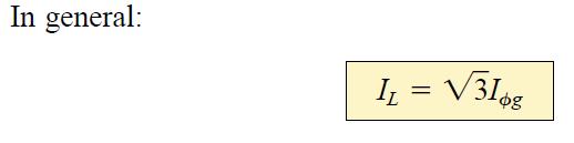
3 3 In this system, the phase and line voltages are equivalent and equal to the voltage induced across each coil of the generator; that is, Note that only one voltage (magnitude) is available instead of the two available in the Y-connected system. Unlike the line current for the Y-connected generator, the line current for the - connected system is not equal to the phase current. The relationship between the two can be found by applying Kirchhoff s current law at one of the nodes and solving for the line current in terms of the phase currents; that is, at node A,
4 The phasor diagram for a balanced load 4
5 5


6 6 with the phase angle between a line current and the nearest phase current at 30. The phasor diagram of the currents is shown as below It can be shown in the same manner employed for the voltages of a Y-connected generator that the phasor sum of the line currents or phase currents for -connected systems with balanced loads is zero.

7 PHASE SEQUENCE ( -CONNECTED GENERATOR) 7
8 8 The basic equations necessary to analyze either of the two systems ( -, -Y) have been presented. We will therefore proceed directly to two descriptive examples, one with a -connected load and one with a Y-connected load. EXAMPLE : For the - system shown in Fig.: a. Find the phase angles θ 2 and θ 3 for the specified phase sequence. b. Find the current in each phase of the load. c. Find the magnitude of the line currents.

9 9 EXAMPLE : For the - system shown in Fig.: a. Find the phase angles θ 2 and θ 3 for the specified phase sequence. b. Find the current in each phase of the load. c. Find the magnitude of the line currents.
10 10

11 EXAMPLE: For the -Y system shown in Fig. below: a. Find the voltage across each phase of the load. b. Find the magnitude of the line voltages. 11
12 12
13 13 POWER CALCULATIONS FOR THREE PHASE SYSTEMS 1. Y-Connected Balanced Load

14 a) Average Power: The average power delivered to each phase can be determined by any one of following Eqs.: 14
")
15 15 b) Reactive Power: The reactive power of each phase (in volt-amperes reactive) is
 Power")
16 16 c) Apparent Power: The apparent power of each phase is d) Power Factor:
17 EXAMPLE: For the -Y connected load of Fig. below, find the total average, reactive, and apparent power. In addition, find the power factor of the load. 17
18 18
19 19
20 EXAMPLE: Each transmission line of the three-wire, three-phase system of Fig. below has an impedance of 15+ j 20. The system delivers a total power of 160 kw at 12,000 V to a balanced three-phase load with a lagging power factor of
21 below 21
22 22

23 23 Power Measurement for Three Phase Systems Two Wattmeter Method: The power delivered to a balanced or an unbalanced four-wire, Y-connected load can be found by the three-wattmeter method, that is, by using three wattmeters in the manner shown in Fig. below. Each wattmeter measures the power delivered to each phase. The potential coil of each wattmeter is connected parallel with the load, while the current coil is in series with the load. The total average power of the system can be found by summing the three wattmeter readings; that is,


24 24 For the load (balanced or unbalanced), the wattmeters are connected as shown in Fig. below. The total power is again the sum of the three wattmeter readings: If in either of the cases just described the load is balanced, the power delivered to each phase will be the same. The total power is then just three times any one wattmeter reading.


25 Two Wattmeter Method: The power delivered to a three-phase, three-wire, - or Y-connected, balanced or unbalanced load can be found using only two wattmeters if the proper connection is employed and if the wattmeter readings are interpreted properly. The basic connections of this two-wattmeter method are shown in Fig. below. One end of each potential coil is connected to the same line. The current coils are then placed in the remaining lines. 25
26 26
27 27
28 28
29 29
30 30 Active Power Measurement via Two Wattmeters The phasor diagram using the two-wattmeter method, for a three-phase balanced starconnected circuit is shown in Fig. on previous slide. The phase currents lags the respective
31 31
32 32 DETERMINATION OF POWER FACTOR FOR THE BALANCED LOAD Since,
33 33
34 34
35 35
36 36
37 37
38 38
39 39
Polyphase Systems. Dr Gamal Sowilam
 Polyphase Systems Dr Gamal Sowilam OBJECTIVES Become familiar with the operation of a three-phase generator and the magnitude and phase relationship connecting the three phase voltages. Be able to calculate
ESO 210 Introduction to Electrical Engineering
 ESO 210 Introduction to Electrical Engineering Lecture-12 Three Phase AC Circuits Three Phase AC Supply 2 3 In general, three-phase systems are preferred over single-phase systems for the transmission
Electric Circuits II Three-Phase Circuits. Dr. Firas Obeidat
 Electric Circuits II Three-Phase Circuits Dr. Firas Obeidat 1 Table of Contents 1 Balanced Three-Phase Voltages 2 Balanced Wye-Wye Connection 3 Balanced Wye-Delta Connection 4 Balanced Delta-Delta Connection
EE 221 CIRCUITS II. Chapter 12 Three-Phase Circuit
 EE 221 CRCUTS Chapter 12 Three-Phase Circuit 1 THREE-PHASE CRCUTS CHAPTER 12 12.1 What is a Three-Phase Circuit? 12.2 Balanced Three-Phase oltages 12.3 Balanced Three-Phase Connection 12.4 Power in a Balanced
CHAPTER 11. Balanced Three-Phase Circuits
 CHAPTER 11 Balanced Three-Phase Circuits 11.1 Balanced Three-Phase Voltages Three sinusoidal voltages Identical amplitudes and frequencies Out of phase 120 with each other by exactly As the a-phase voltage,
KINGS COLLEGE OF ENGINEERING DEPARTMENT OF ELECTRICAL AND ELECTRONICS ENGINEERING QUESTION BANK UNIT I BASIC CIRCUITS ANALYSIS PART A (2-MARKS)
") KINGS COLLEGE OF ENGINEERING DEPARTMENT OF ELECTRICAL AND ELECTRONICS ENGINEERING QUESTION BANK YEAR / SEM : I / II SUBJECT CODE & NAME : EE 1151 CIRCUIT THEORY UNIT I BASIC CIRCUITS ANALYSIS PART A (2-MARKS)
KINGS COLLEGE OF ENGINEERING DEPARTMENT OF ELECTRICAL AND ELECTRONICS ENGINEERING QUESTION BANK YEAR / SEM : I / II SUBJECT CODE & NAME : EE 1151 CIRCUIT THEORY UNIT I BASIC CIRCUITS ANALYSIS PART A (2-MARKS)
Chapter 7. Copyright The McGraw-Hill Companies, Inc. Permission required for reproduction or display.
 Chapter 7 Copyright The McGraw-Hill Companies, Inc. Permission required for reproduction or display. Learning Objectives 1. Understand the meaning of instantaneous and average power, master AC power notation,
Study Guide for Chapter 11
 Study Guide for Chapter 11 Objectives: 1. Know how to analyze a balanced, three-phase Y-Y connected circuit. 2. Know how to analyze a balanced, three-phase Y-Δ connected circuit. 3. Be able to calculate
QUESTION BANK ETE (17331) CM/IF. Chapter1: DC Circuits
 CM/IF. Chapter1: DC Circuits") QUESTION BANK ETE (17331) CM/IF Chapter1: DC Circuits Q1. State & explain Ohms law. Also explain concept of series & parallel circuit with the help of diagram. 3M Q2. Find the value of resistor in fig.
QUESTION BANK ETE (17331) CM/IF Chapter1: DC Circuits Q1. State & explain Ohms law. Also explain concept of series & parallel circuit with the help of diagram. 3M Q2. Find the value of resistor in fig.
Exercise 1: Series RLC Circuits
 RLC Circuits AC 2 Fundamentals Exercise 1: Series RLC Circuits EXERCISE OBJECTIVE When you have completed this exercise, you will be able to analyze series RLC circuits by using calculations and measurements.
Aligarh College of Engineering & Technology (College Code: 109) Affiliated to UPTU, Approved by AICTE Electrical Engg.
 Affiliated to UPTU, Approved by AICTE Electrical Engg.") Aligarh College of Engineering & Technology (College Code: 19) Electrical Engg. (EE-11/21) Unit-I DC Network Theory 1. Distinguish the following terms: (a) Active and passive elements (b) Linearity and
Aligarh College of Engineering & Technology (College Code: 19) Electrical Engg. (EE-11/21) Unit-I DC Network Theory 1. Distinguish the following terms: (a) Active and passive elements (b) Linearity and
EE 221 CIRCUITS II. Chapter 12 Three-Phase Circuit
 EE 221 CIRCUITS II Chapter 12 Three-Phase Circuit 1 THREE-PHASE CIRCUITS CHAPTER 12 12.1 What is a Three-Phase Circuit? 12.2 Balanced Three-Phase Voltages 12.3 Balanced Three-Phase Connection 12.4 Power
Experiment 45. Three-Phase Circuits. G 1. a. Using your Power Supply and AC Voltmeter connect the circuit shown OBJECTIVE
 Experiment 45 Three-Phase Circuits OBJECTIVE To study the relationship between voltage and current in three-phase circuits. To learn how to make delta and wye connections. To calculate the power in three-phase
AC Power Instructor Notes
 Chapter 7: AC Power Instructor Notes Chapter 7 surveys important aspects of electric power. Coverage of Chapter 7 can take place immediately following Chapter 4, or as part of a later course on energy
Transformer & Induction M/C
 UNIT- 2 SINGLE-PHASE TRANSFORMERS 1. Draw equivalent circuit of a single phase transformer referring the primary side quantities to secondary and explain? (July/Aug - 2012) (Dec 2012) (June/July 2014)
V.S.B ENGINEERING COLLEGE DEPARTMENT OF ELECTRICAL AND ELECTRONICS ENGINEERING I EEE-II Semester all subjects 2 & 16 marks QB
 V.S.B ENGINEERING COLLEGE DEPARTMENT OF ELECTRICAL AND ELECTRONICS ENGINEERING I EEE-II Semester all subjects 2 & 16 marks QB Sl.No Subject Name Page No. 1 Circuit Theory 2 1 UNIT-I CIRCUIT THEORY TWO
ECE215 Lecture 7 Date:
 Lecture 7 Date: 29.08.2016 AC Circuits: Impedance and Admittance, Kirchoff s Laws, Phase Shifter, AC bridge Impedance and Admittance we know: we express Ohm s law in phasor form: where Z is a frequency-dependent
Electrical Theory. Power Principles and Phase Angle. PJM State & Member Training Dept. PJM /22/2018
 Electrical Theory Power Principles and Phase Angle PJM State & Member Training Dept. PJM 2018 Objectives At the end of this presentation the learner will be able to: Identify the characteristics of Sine
CHAPTER 9. Sinusoidal Steady-State Analysis
 CHAPTER 9 Sinusoidal Steady-State Analysis 9.1 The Sinusoidal Source A sinusoidal voltage source (independent or dependent) produces a voltage that varies sinusoidally with time. A sinusoidal current source
Module 1. Introduction. Version 2 EE IIT, Kharagpur
 Module 1 Introduction Lesson 1 Introducing the Course on Basic Electrical Contents 1 Introducing the course (Lesson-1) 4 Introduction... 4 Module-1 Introduction... 4 Module-2 D.C. circuits.. 4 Module-3
VOLTAGE AND CURRENT RELATIONS AND POWER PART1: THREE PHASE VOLTAGE AND CURRENT RELATIONSHIPS
 Islamic University of Gaza Faculty of Engineering Electrical Engineering department Electric Machine Lab Eng. Omar A. Qarmout Eng. Amani S. Abu Reyala Experiment 2 THREE PHASE AC CIRCUITS: VOLTAGE AND
ELEN 140 ELECTRICAL CIRCUITS II Winter 2013
 ELEN 140 ELECTRICAL CIRCUITS II Winter 2013 Professor: Stephen O Loughlin Prerequisite: ELEN 130 Office: C234B Co-requisite: none Office Ph: (250) 762-5445 ext 4376 Lecture: 3.0 hrs/week Email: soloughlin@okanagan.bc.ca
UNIVERSITY OF TECHNOLOGY By: Fadhil A. Hasan ELECTRICAL MACHINES
 UNIVERSITY OF TECHNOLOGY DEPARTMENT OF ELECTRICAL ENGINEERING Year: Second 2016-2017 By: Fadhil A. Hasan ELECTRICAL MACHINES І Module-II: AC Transformers o Single phase transformers o Three-phase transformers
CHAPTER 2. Basic Concepts, Three-Phase Review, and Per Unit
 CHAPTER 2 Basic Concepts, Three-Phase Review, and Per Unit 1 AC power versus DC power DC system: - Power delivered to the load does not fluctuate. - If the transmission line is long power is lost in the
Sample Question Paper
 Scheme G Sample Question Paper Course Name : Electrical Engineering Group Course Code : EE/EP Semester : Third Subject Title : Electrical Circuit and Network 17323 Marks : 100 Time: 3 hrs Instructions:
WALJAT COLLEGES OF APPLIED SCIENCES In academic partnership with BIRLA INSTITUTE OF TECHNOLOGY Question Bank Course: EC Session:
 WLJT OLLEGES OF PPLIED SIENES In academic partnership with IRL INSTITUTE OF TEHNOLOGY Question ank ourse: E Session: 20052006 Semester: II Subject: E2001 asic Electrical Engineering 1. For the resistive
Question Paper Profile
 I Scheme Question Paper Profile Program Name : Electrical Engineering Program Group Program Code : EE/EP/EU Semester : Third Course Title : Electrical Circuits Max. Marks : 70 Time: 3 Hrs. Instructions:
ECE 2006 University of Minnesota Duluth Lab 11. AC Circuits
 1. Objective AC Circuits In this lab, the student will study sinusoidal voltages and currents in order to understand frequency, period, effective value, instantaneous power and average power. Also, the
UNIT 1 CIRCUIT ANALYSIS 1 What is a graph of a network? When all the elements in a network is replaced by lines with circles or dots at both ends.
 UNIT 1 CIRCUIT ANALYSIS 1 What is a graph of a network? When all the elements in a network is replaced by lines with circles or dots at both ends. 2 What is tree of a network? It is an interconnected open
MAHARASHTRA STATE BOARD OF TECHNICAL EDUCATION
 Important Instructions to examiners: 1. The answers should be examined by key words and not as word-to-word as given in the model answer scheme. 2. The model answer and the answer written by candidate
Questions Bank of Electrical Circuits
 Questions Bank of Electrical Circuits 1. If a 100 resistor and a 60 XL are in series with a 115V applied voltage, what is the circuit impedance? 2. A 50 XC and a 60 resistance are in series across a 110V
86 chapter 2 Transformers
 86 chapter 2 Transformers Wb 1.2x10 3 0 1/60 2/60 3/60 4/60 5/60 6/60 t (sec) 1.2x10 3 FIGURE P2.2 2.3 A single-phase transformer has 800 turns on the primary winding and 400 turns on the secondary winding.
VALLIAMMAI ENGINEERING COLLEGE
 P a g e 2 Question Bank Programme Subject Semester / Branch : BE : EE6201-CIRCUIT THEORY : II/EEE,ECE &EIE UNIT-I PART-A 1. Define Ohm s Law (B.L.T- 1) 2. List and define Kirchoff s Laws for electric circuits.
UEENEEG048B Solve problems in complex multi-path power circuits SAMPLE. Version 4. Training and Education Support Industry Skills Unit Meadowbank
 UEE07 Electrotechnology Training Package UEENEEG048B Solve problems in complex multi-path power circuits Learner guide Version 4 Training and Education Support Industry Skills Unit Meadowbank Product Code:
Hours / 100 Marks Seat No.
 17323 14115 3 Hours / 100 Seat No. Instructions (1) All Questions are Compulsory. (2) Illustrate your answers with neat sketches wherever necessary. (3) Figures to the right indicate full marks. (4) Assume
B.Tech II SEM Question Bank. Electronics & Electrical Engg UNIT-1
 UNIT-1 1. State & Explain Superposition theorem & Thevinin theorem with example? 2. Calculate the current in the 400Ωm resistor of below figure by Superposition theorem. 3. State & Explain node voltage
Transmission Line Models Part 1
 Transmission Line Models Part 1 Unlike the electric machines studied so far, transmission lines are characterized by their distributed parameters: distributed resistance, inductance, and capacitance. The
Chapter Objectives: Payam zarbakhsh EElE301 Circuit Theory II Department of Electrical and Electronic Engineering Cyprus International university
 Chapter 12 Three Phase Circuits Chapter Objectives: Be familiar with different three-phase configurations and how to analyze them. Know the difference between balanced and unbalanced circuits Learn about
The Two-Wattmeter Method
 The Two-Wattmeter Method In a three phase, wye or delta three wire system, under balanced or unbalanced conditions, with any power factor, the two-wattmeter method is a practical and commonly used method
Basic Electrical Engineering
 Basic Electrical Engineering S.N. Singh Basic Electrical Engineering S.N. Singh Professor Department of Electrical Engineering Indian Institute of Technology Kanpur PHI Learning Private Limited New Delhi-110001
CHAPTER 6: ALTERNATING CURRENT
 CHAPTER 6: ALTERNATING CURRENT PSPM II 2005/2006 NO. 12(C) 12. (c) An ac generator with rms voltage 240 V is connected to a RC circuit. The rms current in the circuit is 1.5 A and leads the voltage by
Experiment No. Experiments for First Year Electrical Engg Lab
 Experiment No im: To determine Regulation and Efficiency of a single phase transformer using open circuit (O.C.) and short circuit (S.C.) tests pparatus: - Single phase transformer Single phase dimmer
Lab 1: Basic RL and RC DC Circuits
 Name- Surname: ID: Department: Lab 1: Basic RL and RC DC Circuits Objective In this exercise, the DC steady state response of simple RL and RC circuits is examined. The transient behavior of RC circuits
Transformers. gpmacademics.weebly.com
 TRANSFORMERS Syllabus: Principles of operation, Constructional Details, Losses and efficiency, Regulation of Transformer, Testing: OC & SC test. TRANSFORMER: It is a static device which transfers electric
Chapter 11. Alternating Current
 Unit-2 ECE131 BEEE Chapter 11 Alternating Current Objectives After completing this chapter, you will be able to: Describe how an AC voltage is produced with an AC generator (alternator) Define alternation,
CHAPTER 2. Transformers. Dr Gamal Sowilam
 CHAPTER Transformers Dr Gamal Sowilam Introduction A transformer is a static machine. It is not an energy conversion device, it is indispensable in many energy conversion systems. A transformer essentially
Worksheet for Exploration 31.1: Amplitude, Frequency and Phase Shift
 Worksheet for Exploration 31.1: Amplitude, Frequency and Phase Shift We characterize the voltage (or current) in AC circuits in terms of the amplitude, frequency (period) and phase. The sinusoidal voltage
VETRI VINAYAHA COLLEGE OF ENGINEERING AND TECHNOLOGY
 VETRI VINAYAHA COLLEGE OF ENGINEERING AND TECHNOLOGY DEPARTMENT OF ELECTRICAL AND ELECTRONICS ENGINEERING I-YEAR/II-SEMESTER- EEE&ECE EE6201- CIRCUIT THEORY Two Marks with Answers PREPARED BY: Mr.A.Thirukkumaran,
EE 340 Power Transformers
 EE 340 Power Transformers Preliminary considerations A transformer is a device that converts one AC voltage to another AC voltage at the same frequency. It consists of one or more coil(s) of wire wrapped
2015 ELECTRICAL SCIENCE
 Summer 2015 ELECTRICAL SCIENCE TIME: THREE HOURS Maximum Marks : 100 Answer five questions, taking ANY TWO from GROUP A, ANY TWO from GROUP B and from GROUP C. All parts of a question (a,b,etc) should
ESO 210 Introduction to Electrical Engineering
 ESO 210 Introduction to Electrical Engineering Lecture-19 Magnetic Circuits and Introduction to Transformers 2 SERIES CONNECTION OF MUTUALLY COUPLED COILS A mutual term will alter the total inductance
Reg. No. : BASIC ELECTRICAL TECHNOLOGY (ELE 101)
") Department of Electrical and Electronics Engineering Reg. No. : MNIPL INSTITUTE OF TECHNOLOGY, MNIPL ( Constituent Institute of Manipal University, Manipal) FIRST SEMESTER B.E. DEGREE MKEUP EXMINTION (REVISED
Department of Electrical and Electronics Engineering Reg. No. : MNIPL INSTITUTE OF TECHNOLOGY, MNIPL ( Constituent Institute of Manipal University, Manipal) FIRST SEMESTER B.E. DEGREE MKEUP EXMINTION (REVISED
THE SINUSOIDAL WAVEFORM
 Chapter 11 THE SINUSOIDAL WAVEFORM The sinusoidal waveform or sine wave is the fundamental type of alternating current (ac) and alternating voltage. It is also referred to as a sinusoidal wave or, simply,
Review: Lecture 9. Instantaneous and Average Power. Effective or RMS Value. Apparent Power and Power Factor. Complex Power. Conservation of AC Power
 Review: Lecture 9 Instantaneous and Average Power p( t) VmI m cos ( v i ) VmI m cos ( t v i ) Maximum Average Power Transfer Z L R L jx Effective or RMS Value I rms I m L R P * TH Apparent Power and Power
ET1210: Module 5 Inductance and Resonance
 Part 1 Inductors Theory: When current flows through a coil of wire, a magnetic field is created around the wire. This electromagnetic field accompanies any moving electric charge and is proportional to
Downloaded from / 1
 PURWANCHAL UNIVERSITY II SEMESTER FINAL EXAMINATION-2008 LEVEL : B. E. (Computer/Electronics & Comm.) SUBJECT: BEG123EL, Electrical Engineering-I Full Marks: 80 TIME: 03:00 hrs Pass marks: 32 Candidates
Contents. Core information about Unit
 1 Contents Core information about Unit UEENEEH114A - Troubleshoot resonance circuits......3 UEENEEG102A Solve problems in low voltage AC circuits...5 TextBook...7 Topics and material Week 1...9 2 Core
Electrical Machines I : Transformers
 UNIT TRANSFORMERS PART A (Q&A) 1. What is step down transformer? The transformer used to step down the voltage from primary to secondary is called as step down transformer. (Ex: /11).. Draw the noload
ELECTRIC CIRCUITS. Third Edition JOSEPH EDMINISTER MAHMOOD NAHVI
 ELECTRIC CIRCUITS Third Edition JOSEPH EDMINISTER MAHMOOD NAHVI Includes 364 solved problems --fully explained Complete coverage of the fundamental, core concepts of electric circuits All-new chapters
Chapter 33. Alternating Current Circuits
 Chapter 33 Alternating Current Circuits C HAP T E O UTLI N E 33 1 AC Sources 33 2 esistors in an AC Circuit 33 3 Inductors in an AC Circuit 33 4 Capacitors in an AC Circuit 33 5 The L Series Circuit 33
Spring 2000 EE361: MIDTERM EXAM 1
 NAME: STUDENT NUMBER: Spring 2000 EE361: MIDTERM EXAM 1 This exam is open book and closed notes. Assume f=60 hz and use the constant µ o =4π 10-7 wherever necessary. Be sure to show all work clearly. 1.
Transformers 21.1 INTRODUCTION 21.2 MUTUAL INDUCTANCE
 21 Transformers 21.1 INTRODUCTION Chapter 12 discussed the self-inductance of a coil. We shall now examine the mutual inductance that exists between coils of the same or different dimensions. Mutual inductance
Exercise 2: Parallel RLC Circuits
 RLC Circuits AC 2 Fundamentals Exercise 2: Parallel RLC Circuits EXERCSE OBJECTVE When you have completed this exercise, you will be able to analyze parallel RLC circuits by using calculations and measurements.
Bakiss Hiyana binti Abu Bakar JKE, POLISAS BHAB
 1 Bakiss Hiyana binti Abu Bakar JKE, POLISAS 1. Explain AC circuit concept and their analysis using AC circuit law. 2. Apply the knowledge of AC circuit in solving problem related to AC electrical circuit.
TRANSFORMERS PART A. 2. What is the turns ratio and transformer ratio of transformer? Turns ratio = N2/ N1 Transformer = E2/E1 = I1/ I2 =K
 UNIT II TRANSFORMERS PART A 1. Define a transformer? A transformer is a static device which changes the alternating voltage from one level to another. 2. What is the turns ratio and transformer ratio of
Branch Current Method
 Script Hello friends. In this series of lectures we have been discussing the various types of circuits, the voltage and current laws and their application to circuits. Today in this lecture we shall be
TRANSFORMER THEORY. Mutual Induction
 Transformers Transformers are used extensively for AC power transmissions and for various control and indication circuits. Knowledge of the basic theory of how these components operate is necessary to
Techniques for Passive Circuit Analysis for. State Space Differential Equations
 Techniques for Passive Circuit Analysis for chp4 1 State Space Differential Equations 1. Draw circuit schematic and label components (e.g., R 1, R 2, C 1, L 1 ) 2. Assign voltage at each node (e.g., e
EE6201 CIRCUIT THEORY QUESTION BANK PART A
 EE6201 CIRCUIT THEORY 1. State ohm s law. 2. State kirchoff s law. QUESTION BANK PART A 3. Which law is applicable for branch current method? 4. What is the matrix formation equation for mesh and nodal
5.0 THREE PHASE SYSTEM
 5.0 THREE PHASE SYSTEM ET 201 BAKISS HIYANA BAU BAKAR JKE, POLISAS 1 COURSE LEARNING OUTCOME 1. Explain AC circuit concept and their analysis using AC circuit law. 2. Apply the knowledge of AC circuit
CHAPTER THREE PHASE SYSTEM (3 Φ ) C h a p t e r 3 71
 C h a p t e r 3 71") C h a p t e r 3 71 CHATE 3 THEE HASE SSTEM (3 Φ ) 3.0 NTODUCTON This chapter is explaining about the three phase system. The learning outcome is student should be able to apply the principles of three
C h a p t e r 3 71 CHATE 3 THEE HASE SSTEM (3 Φ ) 3.0 NTODUCTON This chapter is explaining about the three phase system. The learning outcome is student should be able to apply the principles of three
ECE 215 Lecture 8 Date:
 ECE 215 Lecture 8 Date: 28.08.2017 Phase Shifter, AC bridge AC Circuits: Steady State Analysis Phase Shifter the circuit current I leads the applied voltage by some phase angle θ, where 0 < θ < 90 ο depending
AC reactive circuit calculations
 AC reactive circuit calculations This worksheet and all related files are licensed under the Creative Commons Attribution License, version 1.0. To view a copy of this license, visit http://creativecommons.org/licenses/by/1.0/,
Code No: RR Set No. 1
 Code No: RR310202 Set No. 1 III B.Tech I Semester Regular Examinations, November 2006 ELECTRICAL MEASUREMENTS (Electrical & Electronic Engineering) Time: 3 hours Max Marks: 80 Answer any FIVE Questions
2.0 AC CIRCUITS 2.1 AC VOLTAGE AND CURRENT CALCULATIONS. ECE 4501 Power Systems Laboratory Manual Rev OBJECTIVE
 2.0 AC CIRCUITS 2.1 AC VOLTAGE AND CURRENT CALCULATIONS 2.1.1 OBJECTIVE To study sinusoidal voltages and currents in order to understand frequency, period, effective value, instantaneous power and average
BEE COURSE FILE PREPARED BY: BHARTI TUNDWAL (ECE DEPARTMENT)
") BEE COURSE FILE PREPARED BY: BHARTI TUNDWAL (ECE DEPARTMENT) DELHI COLLEGE OF TECHNOLOGY& MANAGEMENT, PALWAL ACADEMIC CALENDAR RECORD NO.: QF/ACD/01 Revision No.: 00 ACADEMIC CALENDER OF B.TECH, M.TECH,
BEE COURSE FILE PREPARED BY: BHARTI TUNDWAL (ECE DEPARTMENT) DELHI COLLEGE OF TECHNOLOGY& MANAGEMENT, PALWAL ACADEMIC CALENDAR RECORD NO.: QF/ACD/01 Revision No.: 00 ACADEMIC CALENDER OF B.TECH, M.TECH,
Experiment 1 Alternating Current with Coil and Ohmic Resistors
 Experiment Alternating Current with Coil and Ohmic esistors - Objects of the experiment - Determining the total impedance and the phase shift in a series connection of a coil and a resistor. - Determining
MCQ Questions. Elements of Electrical Engineering (EEE)
") MCQ Questions 1. The length of conductor is doubled and its area of cross section is also doubled, then the resistance will. a. Increase four time b. Remain unchanged c. Decrease to four times d. Change
MCQ Questions 1. The length of conductor is doubled and its area of cross section is also doubled, then the resistance will. a. Increase four time b. Remain unchanged c. Decrease to four times d. Change
ECE 321 Experiment No: 4 Energy Systems Lab 1 Fall 2009 TRANSFORMERS-1
 TRANSFORMER: EXPERIMENT NO 4 TRANSFORMERS-1 The transformer, which is made up of two or more coils or windings linked magnetically, with or without a core to shape and enhance the magnetic flux, is used
SHRI RAMSWAROOP MEMORIAL COLLEGE OF ENGG. & MANAGEMENT B.Tech. [SEM I (EE, EN, EC, CE)] QUIZ TEST-3 (Session: ) Time: 1 Hour ELECTRICAL ENGINEE
![SHRI RAMSWAROOP MEMORIAL COLLEGE OF ENGG. & MANAGEMENT B.Tech. [SEM I (EE, EN, EC, CE)] QUIZ TEST-3 (Session: ) Time: 1 Hour ELECTRICAL ENGINEE](/thumbs/94/118213481.jpg "SHRI RAMSWAROOP MEMORIAL COLLEGE OF ENGG. & MANAGEMENT B.Tech. [SEM I (EE, EN, EC, CE)] QUIZ TEST-3 (Session: ) Time: 1 Hour ELECTRICAL ENGINEE") SHRI RAMSWAROOP MEMORIAL COLLEGE OF ENGG. & MANAGEMENT B.Tech. [SEM I (EE, EN, EC, CE)] QUIZ TEST-3 (Session: 2014-15) Time: 1 Hour ELECTRICAL ENGINEERING Max. Marks: 30 (NEE-101) Roll No. Academic/26
SHRI RAMSWAROOP MEMORIAL COLLEGE OF ENGG. & MANAGEMENT B.Tech. [SEM I (EE, EN, EC, CE)] QUIZ TEST-3 (Session: 2014-15) Time: 1 Hour ELECTRICAL ENGINEERING Max. Marks: 30 (NEE-101) Roll No. Academic/26
3.1.Introduction. Synchronous Machines
 3.1.Introduction Synchronous Machines A synchronous machine is an ac rotating machine whose speed under steady state condition is proportional to the frequency of the current in its armature. The magnetic
SAMPLE EXAM PROBLEM PROTECTION (6 OF 80 PROBLEMS)
") SAMPLE EXAM PROBLEM PROTECTION (6 OF 80 PROBLEMS) SLIDE In this video, we will cover a sample exam problem for the Power PE Exam. This exam problem falls under the topic of Protection, which accounts for
SAMPLE EXAM PROBLEM PROTECTION (6 OF 80 PROBLEMS) SLIDE In this video, we will cover a sample exam problem for the Power PE Exam. This exam problem falls under the topic of Protection, which accounts for
Exercise 9: inductor-resistor-capacitor (LRC) circuits
 circuits") Exercise 9: inductor-resistor-capacitor (LRC) circuits Purpose: to study the relationship of the phase and resonance on capacitor and inductor reactance in a circuit driven by an AC signal. Introduction
Exercise 9: inductor-resistor-capacitor (LRC) circuits Purpose: to study the relationship of the phase and resonance on capacitor and inductor reactance in a circuit driven by an AC signal. Introduction
Three Phase System. c 2 ω Fig.1a -----(1) Eb1b2 ) -----(2) Ea1a Ea1a2, Eb1b2 & Ec1c2 are RMS values. Ec1c2. Fig.
 Eb1b2 ) -----(2) Ea1a Ea1a2, Eb1b2 & Ec1c2 are RMS values. Ec1c2. Fig.") Three hase System Generation of three hase system: Consider following hase simle loo generator shown in figure a. ts generated voltage will be as shown in figure b. c a c ω b b 4 Fig.a e Sin( ) -----()
Three hase System Generation of three hase system: Consider following hase simle loo generator shown in figure a. ts generated voltage will be as shown in figure b. c a c ω b b 4 Fig.a e Sin( ) -----()
Module 7. Transformer. Version 2 EE IIT, Kharagpur
 Module 7 Transformer Lesson 28 Problem solving on Transformers Contents 28 Problem solving on Transformer (Lesson-28) 4 28.1 Introduction. 4 28.2 Problems on 2 winding single phase transformers. 4 28.3
Alternating current circuits- Series RLC circuits
 FISI30 Física Universitaria II Professor J.. ersosimo hapter 8 Alternating current circuits- Series circuits 8- Introduction A loop rotated in a magnetic field produces a sinusoidal voltage and current.
Cork Institute of Technology. Autumn 2008 Electrical Energy Systems (Time: 3 Hours)
") Cork Institute of Technology Bachelor of Science (Honours) in Electrical Power Systems - Award Instructions Answer FIVE questions. (EELPS_8_Y4) Autumn 2008 Electrical Energy Systems (Time: 3 Hours) Examiners:
Cork Institute of Technology Bachelor of Science (Honours) in Electrical Power Systems - Award Instructions Answer FIVE questions. (EELPS_8_Y4) Autumn 2008 Electrical Energy Systems (Time: 3 Hours) Examiners:
AC Fundamental. Simple Loop Generator: Whenever a conductor moves in a magnetic field, an emf is induced in it.
 AC Fundamental Simple Loop Generator: Whenever a conductor moves in a magnetic field, an emf is induced in it. Fig.: Simple Loop Generator The amount of EMF induced into a coil cutting the magnetic lines
ECE : Circuits and Systems II
 ECE 202-001: Circuits and Systems II Spring 2019 Instructor: Bingsen Wang Classroom: NRB 221 Office: ERC C133 Lecture hours: MWF 8:00 8:50 am Tel: 517/355-0911 Office hours: M,W 3:00-4:30 pm Email: bingsen@egr.msu.edu
Closed circuit complete path for electrons follow. Open circuit no charge flow and no current.
 Section 1 Schematic Diagrams and Circuits Electric Circuits, continued Closed circuit complete path for electrons follow. Open circuit no charge flow and no current. short circuit closed circuit, no load.
Figure Derive the transient response of RLC series circuit with sinusoidal input. [15]
![Figure Derive the transient response of RLC series circuit with sinusoidal input. [15]](/thumbs/84/91046828.jpg "Figure Derive the transient response of RLC series circuit with sinusoidal input. [15]") COURTESY IARE Code No: R09220205 R09 SET-1 B.Tech II Year - II Semester Examinations, December-2011 / January-2012 NETWORK THEORY (ELECTRICAL AND ELECTRONICS ENGINEERING) Time: 3 hours Max. Marks: 80 Answer
COURTESY IARE Code No: R09220205 R09 SET-1 B.Tech II Year - II Semester Examinations, December-2011 / January-2012 NETWORK THEORY (ELECTRICAL AND ELECTRONICS ENGINEERING) Time: 3 hours Max. Marks: 80 Answer
University of Jordan School of Engineering Electrical Engineering Department. EE 219 Electrical Circuits Lab
 University of Jordan School of Engineering Electrical Engineering Department EE 219 Electrical Circuits Lab EXPERIMENT 7 RESONANCE Prepared by: Dr. Mohammed Hawa EXPERIMENT 7 RESONANCE OBJECTIVE This experiment
Objective of the Lecture
 Objective of the Lecture Present Kirchhoff s Current and Voltage Laws. Chapter 5.6 and Chapter 6.3 Principles of Electric Circuits Chapter4.6 and Chapter 5.5 Electronics Fundamentals or Electric Circuit
Transformers. Dr. Gamal Sowilam
 Transformers Dr. Gamal Sowilam OBJECTIVES Become familiar with the flux linkages that exist between the coils of a transformer and how the voltages across the primary and secondary are established. Understand
Kirchhoff s laws. Objectives. Assessment. Assessment. Assessment. Assessment 5/27/14. Apply Kirchhoff s first and second laws.
 Kirchhoff s laws Objectives Apply Kirchhoff s first and second laws. Calculate the current and voltage for resistor circuits connected in parallel. Calculate the current and voltage for resistor circuits
Electrical Circuits (2)
") Electrical Circuits (2) Lecture 1 Intro. & Review Dr.Eng. Basem ElHalawany Course Info Title Electric Circuits (2) Lecturer: Lecturer Webpage: Teaching Assistant (TA) Course Webpage References Software
Electrical Circuits (2) Lecture 1 Intro. & Review Dr.Eng. Basem ElHalawany Course Info Title Electric Circuits (2) Lecturer: Lecturer Webpage: Teaching Assistant (TA) Course Webpage References Software
PART B. t (sec) Figure 1
 Figure 1") Code No: R16128 R16 SET 1 I B. Tech II Semester Regular Examinations, April/May 217 ELECTRICAL CIRCUIT ANALYSIS I (Electrical and Electronics Engineering) Time: 3 hours Max. Marks: 7 Note: 1. Question
Code No: R16128 R16 SET 1 I B. Tech II Semester Regular Examinations, April/May 217 ELECTRICAL CIRCUIT ANALYSIS I (Electrical and Electronics Engineering) Time: 3 hours Max. Marks: 7 Note: 1. Question
ELG 4125: ELECTRICAL POWER TRANSMISSION AND DISTRIBUTION: TUTORIAL 1: - BY:
 ELG 4125: ELECTRICAL POWER TRANSMISSION AND DISTRIBUTION: TUTORIAL 1: - BY: Faizhussain Arsiwala POWER FACTOR: The cosine of angle between voltage and current in an a.c. circuit is known as power factor.
Bhoj Reddy Engineering College for Women, Hyderabad Department of Electronics and Communication Engineering Electrical and Electronics Instrumentation
 Bhoj Reddy Engineering College for Women, Hyderabad Department of Electronics and Communication Engineering Electrical and Electronics Instrumentation Academic Year: 2016-17 III B Tech II Semester Branch:
SECTION 4 TRANSFORMERS. Yilu (Ellen) Liu. Associate Professor Electrical Engineering Department Virginia Tech University
 Liu. Associate Professor Electrical Engineering Department Virginia Tech University") SECTION 4 TRANSFORMERS Yilu (Ellen) Liu Associate Professor Electrical Engineering Department Virginia Tech University Analysis of Transformer Turns Ratio......................... 4.2 Analysis of a Step-Up
SECTION 4 TRANSFORMERS Yilu (Ellen) Liu Associate Professor Electrical Engineering Department Virginia Tech University Analysis of Transformer Turns Ratio......................... 4.2 Analysis of a Step-Up