EE 221 CIRCUITS II. Chapter 12 Three-Phase Circuit
|
|
|
- Simon Fisher
- 5 years ago
- Views:
Transcription
1 EE 221 CIRCUITS II Chapter 12 Three-Phase Circuit 1
2 THREE-PHASE CIRCUITS CHAPTER What is a Three-Phase Circuit? 12.2 Balanced Three-Phase Voltages 12.3 Balanced Three-Phase Connection 12.4 Power in a Balanced System 12.5 Unbalanced Three-Phase Systems 12.6 Application Residential Wiring 2
3 12.1 Advantages of Three-Phase Circuit? 1. Most of the electric power is generated and distributed in three-phase. 2. The instantaneous power in a three-phase system can be constant. 3. The amount of power generated by a three-phase generator is more economical than that of a singlephase generator 4. The amount of wire required for a three-phase system is less than that required for an equivalent singlephase system. 3


4 Schematic Diagram of a Power System

5 US Electric Energy Generation Mix


6 Thermal Power Plants


7 Nuclear Power Plant


8 Natural Gas Power Plants


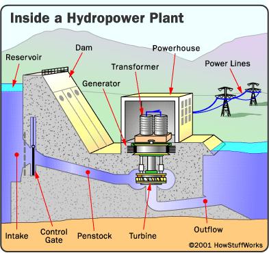

9 Hydro Power Plants


10 Renewable Power Plants
 surrounded by stationary windings (in the stator).")
11 12.2 Balanced Three-Phase Voltages A three-phase generator consists of a rotating magnet (in the rotor) surrounded by stationary windings (in the stator). A three-phase generator The generated voltages 11
12 12.1 Definition of a Three-Phase Circuit It is a system with a generator consisting of three sources having the same amplitude and frequency but out of phase with each other by 120. Three sources with 120 out of phase Four wired system 12
13 12.2 Balanced Three-Phase Voltages Two possible configurations: Three-phase voltage sources: (a) Y-connected ; (b) Δ-connected 13
14 12.2 Balance Three-Phase Voltages Balanced phase voltages are equal in magnitude and are out of phase with each other by 120. The phase sequence is the time order in which the voltages pass through their respective maximum values. a-b-c (or positive sequence) a-c-b (or negative sequence) A balanced load is one in which the phase impedances are equal in magnitude and in phase 14
15 12.2 Balance Three-Phase Voltages Example 1 Determine the phase sequence of the set of voltages. v v v an bn cn 200 cos( ωt + 10 ) 200 cos( ωt 230 ) 200 cos( ωt 110 ) 15
16 12.2 Balanced Three-Phase Voltages Solution: The voltages can be expressed in phasor form as V V V an bn cn V V V We notice that V an leads V cn by 120 and V cn in turn leads V bn by 120. Hence, we have an a-c-b sequence (or negative sequence). 16
17 12.3 Balanced Three-Phase Connection Four possible connections 1. Y-Y connection (Y-connected source with a Y-connected load) 2. Y-Δ connection (Y-connected source with a Δ-connected load) 3. Δ-Δ connection 4. Δ-Y connection 17
18 12.3 Balance Three-Phase Connection A balanced Y-Y system is a three-phase system with a balanced Y-connected source and a balanced Y- connected load. V L V V p L 3V p V, where V an ab V V bn bc V V cn ca I n a b c ( I + I + I ) 0 18
19 12.3 Balanced Three-Phase Connection Example 2: Obtain the line currents 19
20 12.3 Balanced Three-Phase Connection A balanced Y-Δ system is a three-phase system with a balanced Y-connected source and a balanced Δ- connected load. I L 3I p, where I L I a I b I c I p I AB I BC I CA 20
21 12.3 Balanced Three-Phase Connection Example 3: 21
22 12.3 Balanced Three-Phase Connection A balanced Δ-Δ system is a three-phase system with a balanced Δ -connected source and a balanced Δ -connected load. 22
23 12.3 Balance Three-Phase Connection Example 4: 23
24 12.3 Balanced Three-Phase Connection A balanced Δ-Y system is a three-phase system with a balanced y-connected source and a balanced y-connected load. 24
25 12.3 Balanced Three-Phase Connection Example 5: let Find the line currents 25
26 12.4 Power in a Balanced System P Q 3V I cos( θ ) 3V I cos( θ ) p 3V I sin( θ ) 3V I sin( θ ) p L L S 3 VpI 3V L I 26
27 12.3 Balanced Three-Phase Systems Example 6 Determine the total complex power at the source and at the load Ans At the source: S s ( j834.6) VA At the load: S L ( j1113) VA 27
28 12.3 BALANCED LOAD: EXAMPLE 7 28
29 12.5 Unbalanced Three-Phase Systems An unbalanced system is due to unbalanced voltage sources or an unbalanced load. I a V Z AN A, I b V Z BN B, I c V Z CN C, I n (I a + I b + I c ) The total power is not simply three times the power in one phase but the sum of the powers in the three phases. To calculate power in an unbalanced three-phase system requires that we find the power in each phase. 29
30 12.5 UNBALANCED THE-WIRE Y-CONNECTED CIRCUIT 30 Solve the problem again using nodal analysis.
31 12.5 UNBALANCED THE WIRE Δ CONNECTED CIRCUIT Calculate the line currents and total real and reactive power supplied by the source: 31 Rework the problem using a simpler method


32 12.4 Power in a unbalanced System Three Watt-Meter Method: P T P 1 +P 2 +P 3 Two Watt-Meter Method: P T P 1 +P 2 Special case: for a balanced load, the total reactive power may be computed From the readings of the two wattmeters: Q T 3 1 ( P 2 P ) 32
33 2-WATTMETER METHOD The unbalanced load is supplied by a balanced source such that Vab 2080 V with positive phase sequence. Calculate the reading of each wattmeter. 33 Verify the answer by computing the power consumed by each resistor

34 12.6 Application Residential Wiring A 120/240 household power system 34

35 12.6 Application Residential Wiring A typical wiring diagram of a room 35
36 12.6 Application Residential Wiring + 7,600 V - Single-phase three-wire residential wiring 36
37 12.6 Application Residential Wiring 37


38 UTILITY APPLICATION OF CAPACITORS FOR VOLTAGE REGULATION AND POWER TRANSFER Capacitors are placed in series with high Voltage transmission lines to improve voltage Regulation and power transfer capability Capacitor are also used in medium voltage power Distribution lines to regulate voltage and reduce power losses 38

 reading -Remote turn ON and OFF -Communicates with the utility operator in")
39 ENERGY METER (KILO-WATT-HOUR METER) Old electro-mechanical meter records only energy consumed over a time period using mechanical dials. New smart meter records average power, reactive power, power factor, power demand, energy over a period of time, etc -Remote (wireless) reading -Remote turn ON and OFF -Communicates with the utility operator in near-continuous basis -Able to communicate with home appliances such as HVAC thermostat. 39
EE 221 CIRCUITS II. Chapter 12 Three-Phase Circuit
 EE 221 CRCUTS Chapter 12 Three-Phase Circuit 1 THREE-PHASE CRCUTS CHAPTER 12 12.1 What is a Three-Phase Circuit? 12.2 Balanced Three-Phase oltages 12.3 Balanced Three-Phase Connection 12.4 Power in a Balanced
CHAPTER 11. Balanced Three-Phase Circuits
 CHAPTER 11 Balanced Three-Phase Circuits 11.1 Balanced Three-Phase Voltages Three sinusoidal voltages Identical amplitudes and frequencies Out of phase 120 with each other by exactly As the a-phase voltage,
Chapter Objectives: Payam zarbakhsh EElE301 Circuit Theory II Department of Electrical and Electronic Engineering Cyprus International university
 Chapter 12 Three Phase Circuits Chapter Objectives: Be familiar with different three-phase configurations and how to analyze them. Know the difference between balanced and unbalanced circuits Learn about
Electric Circuits II Three-Phase Circuits. Dr. Firas Obeidat
 Electric Circuits II Three-Phase Circuits Dr. Firas Obeidat 1 Table of Contents 1 Balanced Three-Phase Voltages 2 Balanced Wye-Wye Connection 3 Balanced Wye-Delta Connection 4 Balanced Delta-Delta Connection
Study Guide for Chapter 11
 Study Guide for Chapter 11 Objectives: 1. Know how to analyze a balanced, three-phase Y-Y connected circuit. 2. Know how to analyze a balanced, three-phase Y-Δ connected circuit. 3. Be able to calculate
ESO 210 Introduction to Electrical Engineering
 ESO 210 Introduction to Electrical Engineering Lecture-14 Three Phase AC Circuits 2 THE -CONNECTED GENERATOR If we rearrange the coils of the generator as shown in Fig. below the system is referred to
Aligarh College of Engineering & Technology (College Code: 109) Affiliated to UPTU, Approved by AICTE Electrical Engg.
 Affiliated to UPTU, Approved by AICTE Electrical Engg.") Aligarh College of Engineering & Technology (College Code: 19) Electrical Engg. (EE-11/21) Unit-I DC Network Theory 1. Distinguish the following terms: (a) Active and passive elements (b) Linearity and
Aligarh College of Engineering & Technology (College Code: 19) Electrical Engg. (EE-11/21) Unit-I DC Network Theory 1. Distinguish the following terms: (a) Active and passive elements (b) Linearity and
Power and Energy Measurements. MYcsvtu Notes
 Power and Energy Measurements Contest Power measurements DC circuits AC circuits Three-phase systems High-frequency power measurements Energy measurements DC circuits AC circuits Example: Power and energy
ESO 210 Introduction to Electrical Engineering
 ESO 210 Introduction to Electrical Engineering Lecture-12 Three Phase AC Circuits Three Phase AC Supply 2 3 In general, three-phase systems are preferred over single-phase systems for the transmission
ECE 2006 University of Minnesota Duluth Lab 11. AC Circuits
 1. Objective AC Circuits In this lab, the student will study sinusoidal voltages and currents in order to understand frequency, period, effective value, instantaneous power and average power. Also, the
QUESTION BANK ETE (17331) CM/IF. Chapter1: DC Circuits
 CM/IF. Chapter1: DC Circuits") QUESTION BANK ETE (17331) CM/IF Chapter1: DC Circuits Q1. State & explain Ohms law. Also explain concept of series & parallel circuit with the help of diagram. 3M Q2. Find the value of resistor in fig.
QUESTION BANK ETE (17331) CM/IF Chapter1: DC Circuits Q1. State & explain Ohms law. Also explain concept of series & parallel circuit with the help of diagram. 3M Q2. Find the value of resistor in fig.
Chapter 7. Copyright The McGraw-Hill Companies, Inc. Permission required for reproduction or display.
 Chapter 7 Copyright The McGraw-Hill Companies, Inc. Permission required for reproduction or display. Learning Objectives 1. Understand the meaning of instantaneous and average power, master AC power notation,
KINGS COLLEGE OF ENGINEERING DEPARTMENT OF ELECTRICAL AND ELECTRONICS ENGINEERING QUESTION BANK UNIT I BASIC CIRCUITS ANALYSIS PART A (2-MARKS)
") KINGS COLLEGE OF ENGINEERING DEPARTMENT OF ELECTRICAL AND ELECTRONICS ENGINEERING QUESTION BANK YEAR / SEM : I / II SUBJECT CODE & NAME : EE 1151 CIRCUIT THEORY UNIT I BASIC CIRCUITS ANALYSIS PART A (2-MARKS)
KINGS COLLEGE OF ENGINEERING DEPARTMENT OF ELECTRICAL AND ELECTRONICS ENGINEERING QUESTION BANK YEAR / SEM : I / II SUBJECT CODE & NAME : EE 1151 CIRCUIT THEORY UNIT I BASIC CIRCUITS ANALYSIS PART A (2-MARKS)
Three-Phase Induction Motors. By Sintayehu Challa ECEg332:-Electrical Machine I
 Three-Phase Induction Motors 1 2 3 Classification of AC Machines 1. According to the type of current Single Phase and Three phase 2. According to Speed Constant Speed, Variable Speed and Adjustable Speed
Exercise 1: Series RLC Circuits
 RLC Circuits AC 2 Fundamentals Exercise 1: Series RLC Circuits EXERCISE OBJECTIVE When you have completed this exercise, you will be able to analyze series RLC circuits by using calculations and measurements.
Polyphase Systems. Dr Gamal Sowilam
 Polyphase Systems Dr Gamal Sowilam OBJECTIVES Become familiar with the operation of a three-phase generator and the magnitude and phase relationship connecting the three phase voltages. Be able to calculate
Experiment 45. Three-Phase Circuits. G 1. a. Using your Power Supply and AC Voltmeter connect the circuit shown OBJECTIVE
 Experiment 45 Three-Phase Circuits OBJECTIVE To study the relationship between voltage and current in three-phase circuits. To learn how to make delta and wye connections. To calculate the power in three-phase
Circuit Analysis-II. Circuit Analysis-II Lecture # 2 Wednesday 28 th Mar, 18
 Circuit Analysis-II Angular Measurement Angular Measurement of a Sine Wave ü As we already know that a sinusoidal voltage can be produced by an ac generator. ü As the windings on the rotor of the ac generator
Physics 132 Quiz # 23
 Name (please (please print) print) Physics 132 Quiz # 23 I. I. The The current in in an an ac ac circuit is is represented by by a phasor.the value of of the the current at at some time time t t is is
2.0 AC CIRCUITS 2.1 AC VOLTAGE AND CURRENT CALCULATIONS. ECE 4501 Power Systems Laboratory Manual Rev OBJECTIVE
 2.0 AC CIRCUITS 2.1 AC VOLTAGE AND CURRENT CALCULATIONS 2.1.1 OBJECTIVE To study sinusoidal voltages and currents in order to understand frequency, period, effective value, instantaneous power and average
Chapter 12 Three Phase Circuits. Chapter Objectives:
 Chater 12 Three Phase Circuits Chater Objectives: Be familiar with different three-hase configurations and how to analyze them. Know the difference between balanced and unbalanced circuits Learn about
Power Metering Fundamentals Jim Spangler Cirrus Logic 1 March 2011
 Power Metering Fundamentals Jim Spangler Cirrus Logic 1 March 2011 Abstract: This paper defines how to measure electrical energy using electronic wattmeters, for both single phase and multiphase applications
AC Power Instructor Notes
 Chapter 7: AC Power Instructor Notes Chapter 7 surveys important aspects of electric power. Coverage of Chapter 7 can take place immediately following Chapter 4, or as part of a later course on energy
ECE 215 Lecture 8 Date:
 ECE 215 Lecture 8 Date: 28.08.2017 Phase Shifter, AC bridge AC Circuits: Steady State Analysis Phase Shifter the circuit current I leads the applied voltage by some phase angle θ, where 0 < θ < 90 ο depending
3.1.Introduction. Synchronous Machines
 3.1.Introduction Synchronous Machines A synchronous machine is an ac rotating machine whose speed under steady state condition is proportional to the frequency of the current in its armature. The magnetic
Note: 1. All the students must strictly follow all the safety precautions. 2. In case of any question or concern, please contact LAB INSTRUCTOR or TA.
 UNIVERSITY OF WATERLOO ELECTRICAL & COMPUTER ENGINEERING DEPARTMENT FALL 2006 E&CE 261: Energy Systems and Components EXPERIMENT 1: THREE-PHASE SYSTEMS Contents covered in this laboratory exercise: 1.
VALLIAMMAI ENGINEERING COLLEGE
 P a g e 2 Question Bank Programme Subject Semester / Branch : BE : EE6201-CIRCUIT THEORY : II/EEE,ECE &EIE UNIT-I PART-A 1. Define Ohm s Law (B.L.T- 1) 2. List and define Kirchoff s Laws for electric circuits.
EE6201 CIRCUIT THEORY QUESTION BANK PART A
 EE6201 CIRCUIT THEORY 1. State ohm s law. 2. State kirchoff s law. QUESTION BANK PART A 3. Which law is applicable for branch current method? 4. What is the matrix formation equation for mesh and nodal
Look over Chapter 31 sections 1-4, 6, 8, 9, 10, 11 Examples 1-8. Look over Chapter 21 sections Examples PHYS 2212 PHYS 1112
 PHYS 2212 Look over Chapter 31 sections 1-4, 6, 8, 9, 10, 11 Examples 1-8 PHYS 1112 Look over Chapter 21 sections 11-14 Examples 16-18 Good Things To Know 1) How AC generators work. 2) How to find the
CHAPTER 5 DESIGN OF DSTATCOM CONTROLLER FOR COMPENSATING UNBALANCES
 86 CHAPTER 5 DESIGN OF DSTATCOM CONTROLLER FOR COMPENSATING UNBALANCES 5.1 INTRODUCTION Distribution systems face severe power quality problems like current unbalance, current harmonics, and voltage unbalance,
Bakiss Hiyana binti Abu Bakar JKE, POLISAS BHAB
 1 Bakiss Hiyana binti Abu Bakar JKE, POLISAS 1. Explain AC circuit concept and their analysis using AC circuit law. 2. Apply the knowledge of AC circuit in solving problem related to AC electrical circuit.
MILWAUKEE SCHOOL OF ENGINEERING LABORATORY SESSION 4 THREE PHASE TRANSFORMERS
 LABORATORY SESSION 4 THREE PHASE TRANSFORMERS PURPOSE To investigate the three phase transformer connections and characteristics DISCUSSION Most electrical energy is generated and transmitted using three
A) For the Y-Y circuit shown in Fig. 1, find the line currents, the line voltages, and the load voltages.
 For the Y-Y circuit shown in Fig. 1, find the line currents, the line voltages, and the load voltages.") Salman Bin Abdul Aziz University Faculty of Engineering Electrical Engineering department Electric Circuit Analysis (EE 2020) Sheet (2) Three-Phase Circuits < <
Salman Bin Abdul Aziz University Faculty of Engineering Electrical Engineering department Electric Circuit Analysis (EE 2020) Sheet (2) Three-Phase Circuits < <
CHAPTER 6: ALTERNATING CURRENT
 CHAPTER 6: ALTERNATING CURRENT PSPM II 2005/2006 NO. 12(C) 12. (c) An ac generator with rms voltage 240 V is connected to a RC circuit. The rms current in the circuit is 1.5 A and leads the voltage by
Electrical Engineering Fundamentals
 Electrical Engineering Fundamentals EE-238 Sheet 1 Series Circuits 1- For the circuits shown below, the total resistance is specified. Find the unknown resistance and the current for each circuit. 12.6
B.Tech II SEM Question Bank. Electronics & Electrical Engg UNIT-1
 UNIT-1 1. State & Explain Superposition theorem & Thevinin theorem with example? 2. Calculate the current in the 400Ωm resistor of below figure by Superposition theorem. 3. State & Explain node voltage
SHRI RAMSWAROOP MEMORIAL COLLEGE OF ENGG. & MANAGEMENT B.Tech. [SEM I (EE, EN, EC, CE)] QUIZ TEST-3 (Session: ) Time: 1 Hour ELECTRICAL ENGINEE
![SHRI RAMSWAROOP MEMORIAL COLLEGE OF ENGG. & MANAGEMENT B.Tech. [SEM I (EE, EN, EC, CE)] QUIZ TEST-3 (Session: ) Time: 1 Hour ELECTRICAL ENGINEE](/thumbs/94/118213481.jpg "SHRI RAMSWAROOP MEMORIAL COLLEGE OF ENGG. & MANAGEMENT B.Tech. [SEM I (EE, EN, EC, CE)] QUIZ TEST-3 (Session: ) Time: 1 Hour ELECTRICAL ENGINEE") SHRI RAMSWAROOP MEMORIAL COLLEGE OF ENGG. & MANAGEMENT B.Tech. [SEM I (EE, EN, EC, CE)] QUIZ TEST-3 (Session: 2014-15) Time: 1 Hour ELECTRICAL ENGINEERING Max. Marks: 30 (NEE-101) Roll No. Academic/26
SHRI RAMSWAROOP MEMORIAL COLLEGE OF ENGG. & MANAGEMENT B.Tech. [SEM I (EE, EN, EC, CE)] QUIZ TEST-3 (Session: 2014-15) Time: 1 Hour ELECTRICAL ENGINEERING Max. Marks: 30 (NEE-101) Roll No. Academic/26
6. List two possible arrangements of a Yconnection and give one application
 OBJECTIVES PI 26.35-1 Electrical Equipment - Course PI 30.2 THREE PHASE SYSTEMS On completion of this module the student will be able to: 1. In a few sentences explain how three phase voltages are produced
UNIVERSITY OF NORTH CAROLINA AT CHARLOTTE Department of Electrical and Computer Engineering
 UNIVERSITY OF NORTH CAROLINA AT CHARLOTTE Department of Electrical and Computer Engineering EXPERIMENT 10 BALANCED THREE-PHASE NETWORKS OBJECTIVES In this experiment the student will explore balanced three-phase
Electrical Theory. Power Principles and Phase Angle. PJM State & Member Training Dept. PJM /22/2018
 Electrical Theory Power Principles and Phase Angle PJM State & Member Training Dept. PJM 2018 Objectives At the end of this presentation the learner will be able to: Identify the characteristics of Sine
Alternating Current Study Guide. Preface. This module is DIFFICULT.
 Preface This module is DIFFICULT. This material will take more effort to understand and more effort to pass than tests from previous modules. This is on par with a college-level electrical engineering
CHAPTER 3 COMBINED MULTIPULSE MULTILEVEL INVERTER BASED STATCOM
 CHAPTER 3 COMBINED MULTIPULSE MULTILEVEL INVERTER BASED STATCOM 3.1 INTRODUCTION Static synchronous compensator is a shunt connected reactive power compensation device that is capable of generating or
V.S.B ENGINEERING COLLEGE DEPARTMENT OF ELECTRICAL AND ELECTRONICS ENGINEERING I EEE-II Semester all subjects 2 & 16 marks QB
 V.S.B ENGINEERING COLLEGE DEPARTMENT OF ELECTRICAL AND ELECTRONICS ENGINEERING I EEE-II Semester all subjects 2 & 16 marks QB Sl.No Subject Name Page No. 1 Circuit Theory 2 1 UNIT-I CIRCUIT THEORY TWO
Course ELEC Introduction to electric power and energy systems. Additional exercises with answers December reactive power compensation
 Course ELEC0014 - Introduction to electric power and energy systems Additional exercises with answers December 2017 Exercise A1 Consider the system represented in the figure below. The four transmission
Spring 2000 EE361: MIDTERM EXAM 1
 NAME: STUDENT NUMBER: Spring 2000 EE361: MIDTERM EXAM 1 This exam is open book and closed notes. Assume f=60 hz and use the constant µ o =4π 10-7 wherever necessary. Be sure to show all work clearly. 1.
R. W. Erickson. Department of Electrical, Computer, and Energy Engineering University of Colorado, Boulder
 R. W. Erickson Department of Electrical, Computer, and Energy Engineering University of Colorado, Boulder 16.4. Power phasors in sinusoidal systems Apparent power is the product of the rms voltage and
University of Pennsylvania Department of Electrical and Systems Engineering. ESE 206: Electrical Circuits and Systems II - Lab
 University of Pennsylvania Department of Electrical and Systems Engineering ESE 206: Electrical Circuits and Systems II - Lab AC POWER ANALYSIS AND DESIGN I. Purpose and Equipment: Provide experimental
MAHARASHTRA STATE BOARD OF TECHNICAL EDUCATION
 Important Instructions to examiners: 1. The answers should be examined by key words and not as word-to-word as given in the model answer scheme. 2. The model answer and the answer written by candidate
Module 7. Transformer. Version 2 EE IIT, Kharagpur
 Module 7 Transformer Lesson 28 Problem solving on Transformers Contents 28 Problem solving on Transformer (Lesson-28) 4 28.1 Introduction. 4 28.2 Problems on 2 winding single phase transformers. 4 28.3
Level 6 Graduate Diploma in Engineering Electro techniques
 9210-137 Level 6 Graduate Diploma in Engineering Electro techniques Sample Paper You should have the following for this examination one answer book non-programmable calculator pen, pencil, ruler, drawing
Chapter 11 Thre r e e e P has a e e C i C rc r u c its t
 Chater 11 Three Phase Circuits Three hase Circuits An AC generator designed to develo a single sinusoidal voltage for each rotation of the shaft (rotor) is referred to as a single-hase AC generator. If
CHAPTER 9. Sinusoidal Steady-State Analysis
 CHAPTER 9 Sinusoidal Steady-State Analysis 9.1 The Sinusoidal Source A sinusoidal voltage source (independent or dependent) produces a voltage that varies sinusoidally with time. A sinusoidal current source
Module 1. Introduction. Version 2 EE IIT, Kharagpur
 Module 1 Introduction Lesson 1 Introducing the Course on Basic Electrical Contents 1 Introducing the course (Lesson-1) 4 Introduction... 4 Module-1 Introduction... 4 Module-2 D.C. circuits.. 4 Module-3
Module 7. Electrical Machine Drives. Version 2 EE IIT, Kharagpur 1
 Module 7 Electrical Machine Drives Version 2 EE IIT, Kharagpur 1 Lesson 34 Electrical Actuators: Induction Motor Drives Version 2 EE IIT, Kharagpur 2 Instructional Objectives After learning the lesson
Module 5. DC to AC Converters. Version 2 EE IIT, Kharagpur 1
 Module 5 DC to AC Converters Version 2 EE IIT, Kharagpur 1 Lesson 38 Other Popular PWM Techniques Version 2 EE IIT, Kharagpur 2 After completion of this lesson, the reader shall be able to: 1. Explain
ELEN 140 ELECTRICAL CIRCUITS II Winter 2013
 ELEN 140 ELECTRICAL CIRCUITS II Winter 2013 Professor: Stephen O Loughlin Prerequisite: ELEN 130 Office: C234B Co-requisite: none Office Ph: (250) 762-5445 ext 4376 Lecture: 3.0 hrs/week Email: soloughlin@okanagan.bc.ca
Construction Electrician Level 2
 Level 2 Rev. September 2008 Unit: B1 Electrical Code II Level: Two Duration: 120 hours Theory: Practical: 99 hours 21 hours Overview: This unit of instruction is designed to provide the Electrician apprentice
VOLTAGE AND CURRENT RELATIONS AND POWER PART1: THREE PHASE VOLTAGE AND CURRENT RELATIONSHIPS
 Islamic University of Gaza Faculty of Engineering Electrical Engineering department Electric Machine Lab Eng. Omar A. Qarmout Eng. Amani S. Abu Reyala Experiment 2 THREE PHASE AC CIRCUITS: VOLTAGE AND
Chapter 6: Alternating Current
 hapter 6: Alternating urrent 6. Alternating urrent.o 6.. Define alternating current (A) An alternating current (A) is the electrical current which varies periodically with time in direction and magnitude.
PHYSICS - CLUTCH CH 29: ALTERNATING CURRENT.
 !! www.clutchprep.com CONCEPT: ALTERNATING VOLTAGES AND CURRENTS BEFORE, we only considered DIRECT CURRENTS, currents that only move in - NOW we consider ALTERNATING CURRENTS, currents that move in Alternating
Electrical Motor Power Measurement & Analysis
 Electrical Motor Power Measurement & Analysis Understand the basics to drive greater efficiency Test&Measurement Energy is one of the highest cost items in a plant or facility, and motors often consume
Transformers. gpmacademics.weebly.com
 TRANSFORMERS Syllabus: Principles of operation, Constructional Details, Losses and efficiency, Regulation of Transformer, Testing: OC & SC test. TRANSFORMER: It is a static device which transfers electric
Chapter 33. Alternating Current Circuits
 Chapter 33 Alternating Current Circuits Alternating Current Circuits Electrical appliances in the house use alternating current (AC) circuits. If an AC source applies an alternating voltage to a series
Synchronous Generators II EE 340
 Synchronous Generators II EE 340 Generator P-f Curve All generators are driven by a prime mover, such as a steam, gas, water, wind turbines, diesel engines, etc. Regardless the power source, most of prime
Chapter 31 Alternating Current
 Chapter 31 Alternating Current In this chapter we will learn how resistors, inductors, and capacitors behave in circuits with sinusoidally vary voltages and currents. We will define the relationship between
Physics 227: Lecture 11 Circuits, KVL, KCL, Meters
 Physics 227: Lecture 11 Circuits, KVL, KCL, Meters Lecture 10 review: EMF ξ is not a voltage V, but OK for now. Physical emf source has V ab = ξ - Ir internal. Power in a circuit element is P = IV. For
Chapter 33. Alternating Current Circuits
 Chapter 33 Alternating Current Circuits C HAP T E O UTLI N E 33 1 AC Sources 33 2 esistors in an AC Circuit 33 3 Inductors in an AC Circuit 33 4 Capacitors in an AC Circuit 33 5 The L Series Circuit 33
EQUIVALENT CIRCUIT OF A SINGLE-PHASE TRANSFORMER
 Electrical Machines Lab Experiment-No. One Date: 15-11-2016 EQUIVALENT CIRCUIT OF A SINGLE-PHASE TRANSFORMER Aim: The determination of electrical equivalent circuit parameters of a single phase power transformer
Reg. No. : BASIC ELECTRICAL TECHNOLOGY (ELE 101)
") Department of Electrical and Electronics Engineering Reg. No. : MNIPL INSTITUTE OF TECHNOLOGY, MNIPL ( Constituent Institute of Manipal University, Manipal) FIRST SEMESTER B.E. DEGREE MKEUP EXMINTION (REVISED
Department of Electrical and Electronics Engineering Reg. No. : MNIPL INSTITUTE OF TECHNOLOGY, MNIPL ( Constituent Institute of Manipal University, Manipal) FIRST SEMESTER B.E. DEGREE MKEUP EXMINTION (REVISED
I. Introduction to Simple Circuits of Resistors
 2 Problem Set for Dr. Todd Huffman Michaelmas Term I. Introduction to Simple ircuits of esistors 1. For the following circuit calculate the currents through and voltage drops across all resistors. The
EE 340L EXPERIMENT # 3 SYNCHRONOUS GENERATORS
 EE 340L EXPERIMENT # 3 SYNCHRONOUS GENERATORS A. EQUIVALENT CIRCUIT PARAMETERS A.1. OPEN CIRCUIT TEST (a) Mechanically couple the generator with a shunt-excited DC motor as shown in figure 4(a). (b) With
Electrical Machines (EE-343) For TE (ELECTRICAL)
 For TE (ELECTRICAL)") PRACTICALWORKBOOK Electrical Machines (EE-343) For TE (ELECTRICAL) Name: Roll Number: Year: Batch: Section: Semester: Department: N.E.D University of Engineering &Technology, Karachi Electrical Machines
PRACTICALWORKBOOK Electrical Machines (EE-343) For TE (ELECTRICAL) Name: Roll Number: Year: Batch: Section: Semester: Department: N.E.D University of Engineering &Technology, Karachi Electrical Machines
VETRI VINAYAHA COLLEGE OF ENGINEERING AND TECHNOLOGY
 VETRI VINAYAHA COLLEGE OF ENGINEERING AND TECHNOLOGY DEPARTMENT OF ELECTRICAL AND ELECTRONICS ENGINEERING I-YEAR/II-SEMESTER- EEE&ECE EE6201- CIRCUIT THEORY Two Marks with Answers PREPARED BY: Mr.A.Thirukkumaran,
Transformer & Induction M/C
 UNIT- 2 SINGLE-PHASE TRANSFORMERS 1. Draw equivalent circuit of a single phase transformer referring the primary side quantities to secondary and explain? (July/Aug - 2012) (Dec 2012) (June/July 2014)
15. the power factor of an a.c circuit is.5 what will be the phase difference between voltage and current in this
 1 1. In a series LCR circuit the voltage across inductor, a capacitor and a resistor are 30 V, 30 V and 60 V respectively. What is the phase difference between applied voltage and current in the circuit?
CHAPTER 2. Basic Concepts, Three-Phase Review, and Per Unit
 CHAPTER 2 Basic Concepts, Three-Phase Review, and Per Unit 1 AC power versus DC power DC system: - Power delivered to the load does not fluctuate. - If the transmission line is long power is lost in the
Industrial Electrician Level 3
 Industrial Electrician Level 3 Industrial Electrician Unit: C1 Industrial Electrical Code I Level: Three Duration: 77 hours Theory: Practical: 77 hours 0 hours Overview: This unit is designed to provide
Dhanalakshmi Srinivasan Institute of Technology, Samayapuram, Trichy. Cycle 2 EE6512 Electrical Machines II Lab Manual
 Cycle 2 EE652 Electrical Machines II Lab Manual CIRCUIT DIAGRAM FOR SLIP TEST 80V DC SUPPLY 350Ω, 2 A 3 Point Starter L F A NAME PLATE DETAILS: 3Ф alternator DC shunt motor FUSE RATING: Volts: Volts: 25%
University of Jordan School of Engineering Electrical Engineering Department. EE 219 Electrical Circuits Lab
 University of Jordan School of Engineering Electrical Engineering Department EE 219 Electrical Circuits Lab EXPERIMENT 7 RESONANCE Prepared by: Dr. Mohammed Hawa EXPERIMENT 7 RESONANCE OBJECTIVE This experiment
Eyenubo, O. J. & Otuagoma, S. O.
 PERFORMANCE ANALYSIS OF A SELF-EXCITED SINGLE-PHASE INDUCTION GENERATOR By 1 Eyenubo O. J. and 2 Otuagoma S. O 1 Department of Electrical/Electronic Engineering, Delta State University, Oleh Campus, Nigeria
Analysis of Temporary Over-Voltages from Self-Excited Large Induction Motors in the Presence of Resonance - Case Studies
 Analysis of Temporary Over-Voltages from Self-Excited Large Induction Motors in the Presence of Resonance - Case Studies T.G. Martinich, M. Nagpal, A. Bimbhra Abstract-- Technological advancements in high-power
EE42: Running Checklist of Electronics Terms Dick White
 EE42: Running Checklist of Electronics Terms 14.02.05 Dick White Terms are listed roughly in order of their introduction. Most definitions can be found in your text. Terms2 TERM Charge, current, voltage,
AC Circuits. Nikola Tesla
 AC Circuits Nikola Tesla 1856-1943 Mar 26, 2012 Alternating Current Circuits Electrical appliances in the house use alternating current (AC) circuits. If an AC source applies an alternating voltage of
Phasor. Phasor Diagram of a Sinusoidal Waveform
 Phasor A phasor is a vector that has an arrow head at one end which signifies partly the maximum value of the vector quantity ( V or I ) and partly the end of the vector that rotates. Generally, vectors
MCQ Questions. Elements of Electrical Engineering (EEE)
") MCQ Questions 1. The length of conductor is doubled and its area of cross section is also doubled, then the resistance will. a. Increase four time b. Remain unchanged c. Decrease to four times d. Change
MCQ Questions 1. The length of conductor is doubled and its area of cross section is also doubled, then the resistance will. a. Increase four time b. Remain unchanged c. Decrease to four times d. Change
Transformers 3: connections
 CHAPTER 11 Transformers 3: connections Further reading Objectives On completion of this chapter, you should be able to 1. construct a phasor diagram for a three-phase transformer under load, given its
University of North Carolina-Charlotte Department of Electrical and Computer Engineering ECGR 4143/5195 Electrical Machinery Fall 2009
 University of North Carolina-Charlotte Department of Electrical and Computer Engineering ECGR 4143/5195 Electrical Machinery Fall 2009 Problem Set 3 Due: Monday September 28 Recommended Reading: Fitzgerald
Lecture 4 - Three-phase circuits, transformer and transient analysis of RLC circuits. Figure 4.1
 Lecture 4 - Three-phase circuits, transformer and transient analysis of RLC circuits Power supply to sizeable power converters are often from three-phase AC source. A balanced three-phase source consists
Power Quality Issues in Traction Power Systems
 9 Power Quality Issues in Traction Power Systems There are serious power quality issues in traction power systems, including negativesequence currents, current harmonics and low power factor, in addition
ECE215 Lecture 7 Date:
 Lecture 7 Date: 29.08.2016 AC Circuits: Impedance and Admittance, Kirchoff s Laws, Phase Shifter, AC bridge Impedance and Admittance we know: we express Ohm s law in phasor form: where Z is a frequency-dependent
Lecture 22 - Three-phase square-wave inverters
 Lecture - Three-phase square-wave inverters Three-phase voltage-source inverters Three phase bridge inverters can be viewed as extensions of the single-phase bridge circuit, as shown in figure.1. The switching
Generator Protection GENERATOR CONTROL AND PROTECTION
 Generator Protection Generator Protection Introduction Device Numbers Symmetrical Components Fault Current Behavior Generator Grounding Stator Phase Fault (87G) Field Ground Fault (64F) Stator Ground Fault
CHAPTER 5 SYNCHRONOUS GENERATORS
 CHAPTER 5 SYNCHRONOUS GENERATORS Summary: 1. Synchronous Generator Construction 2. The Speed of Rotation of a Synchronous Generator 3. The Internal Generated Voltage of a Synchronous Generator 4. The Equivalent
INTRODUCTION PROPOSED SOLUTION STEPS TAKEN. MATLAB Simulation
 INTRODUCTION In a circuit with reactive (inductive or capacitive) loads, the voltage and current are about 90 degrees out of phase. Inductive loads are mainly found in industries that use heavy equipment
The synchronous machine as a component in the electric power system
 1 The synchronous machine as a component in the electric power system dφ e = dt 2 lectricity generation The synchronous machine is used to convert the energy from a primary energy resource (such as water,
AC generator theory. Resources and methods for learning about these subjects (list a few here, in preparation for your research):
:") AC generator theory This worksheet and all related files are licensed under the Creative Commons Attribution License, version 1.0. To view a copy of this license, visit http://creativecommons.org/licenses/by/1.0/,
AC generator theory This worksheet and all related files are licensed under the Creative Commons Attribution License, version 1.0. To view a copy of this license, visit http://creativecommons.org/licenses/by/1.0/,
Single Phase induction Motor [1/Ch. 36]
![Single Phase induction Motor [1/Ch. 36]](/thumbs/88/116054273.jpg "Single Phase induction Motor [1/Ch. 36]") Single Phase induction Motor [1/h. 6] Equivalent ircuit of a Single-Phase nduction Motor without ore Loss [1/6.5/p.17] A single-phase motor may be looked upon as consisting of two motors, having a common
Single Phase induction Motor [1/h. 6] Equivalent ircuit of a Single-Phase nduction Motor without ore Loss [1/6.5/p.17] A single-phase motor may be looked upon as consisting of two motors, having a common
Week 4: Experiment 24. Using Nodal or Mesh Analysis to Solve AC Circuits with an addition of Equivalent Impedance
 Week 4: Experiment 24 Using Nodal or Mesh Analysis to Solve AC Circuits with an addition of Equivalent Impedance Lab Lectures You have two weeks to complete Experiment 27: Complex Power 2/27/2012 (Pre-Lab
SYNCHRONOUS MACHINES
 SYNCHRONOUS MACHINES The geometry of a synchronous machine is quite similar to that of the induction machine. The stator core and windings of a three-phase synchronous machine are practically identical
Exercise 9: inductor-resistor-capacitor (LRC) circuits
 circuits") Exercise 9: inductor-resistor-capacitor (LRC) circuits Purpose: to study the relationship of the phase and resonance on capacitor and inductor reactance in a circuit driven by an AC signal. Introduction
Exercise 9: inductor-resistor-capacitor (LRC) circuits Purpose: to study the relationship of the phase and resonance on capacitor and inductor reactance in a circuit driven by an AC signal. Introduction