HF Amateur SSB Receiver
|
|
|
- Lester Ellis
- 6 years ago
- Views:
Transcription


1 HF Amateur SSB Receiver PCB Set for radio club project
2
3
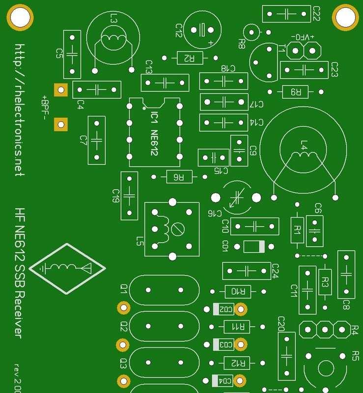
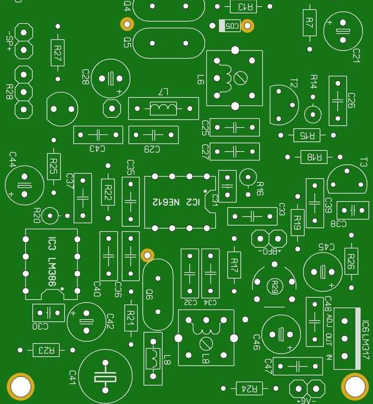
4 PCB for DIY HF Amateur SSB Receiver 20M The receiver is a simple syperheterodyne type with quartz crystal filter. The circuit is based on two NE612 mixer IC s and one audio amplifier LM386. The electrical circuit as it described below in the manual is intended for MHz MHz upper single side band receiving of amateur radio transmissions. However, the PCB allows modifying it for all others amateur SSB radio bands, or making it 2 bands receiver if required. If you are beginner it s strongly recommended to ask someone from your local radio club to help you with components selecting and receiver assembling. The syperhet calibration requires you to have an oscilloscope, DDS HF signal generator, LC Meter, multimeter and soldering tools. Moreover, it requires some basic knowledge of how it works for correct preset of the board. That s why I recommend to ask help of someone experienced if you get trouble with receiver calibration. Each rectangle represent separate operational block. The package includes only 3 PCB s without electronic components: 1. Receiver PCB 2. Band Pass Filer PCB 3. Mini Balun PCB for Beverage Antenna You need to supply all components on the list below. The circuit is designed for 20M receiver. Some components has critical value, please check carefully the part list of the project: You need LC Meter to check precision values of C2, C4, C5, L1, L2 and also compare the inductance of L3 and L4 coils with circuit value. for Band Pass Filter 20M band: C1 = 5pF-20pF trimmer green 6mm C2 = 220pF NP0 (use LC Meter for precision value) C3 = 5pF-20pF trimmer L1 = 10µH axial inductor +-1% (use LC Meter for precision value) L2 = 10µH axial inductor +-1% (use LC Meter for precision value) for Receiver 20M: C4 = 56pF NP0 (use LC Meter for precision value) C5 = 220pF NP0 (use LC Meter for precision value) C6 (optional) C7 C8 (optional) C9 = 10n C10 = 10n
5 C11 C12 C13 C14 C15 C16 C17 C18 C19 C20 C21 C22 C23 C24 C25 C26 C27 C28 C29 C30 C31 C32 C33 C34 C35 C36 C37 C38 C39 C40 C41 C42 C43 C44 C45 C46 C47 C48 = 220µF 16V = 100pF = 100pF NP0 = 5pF-30pF trimmer green 6mm = 100pF = 10pF = 100pF (optional) = 220µF 16V = 10n = 100pF = 10n = 470µF 10V = 100pF = 10pF = 100pF = 47n = 10n = 47n = 470µF 16V = 10µF 16V = 47µF 16V = 220µF 16V = 10µF 16V CD1 = BB910 CD2 = 1SV149 from same batch! CD3 = 1SV149 CD4 = 1SV149 CD5 = 1SV149 Q1 = MHz all crystals have to be +-200Hz max. Q2 = MHz Q3 = MHz Q4 = MHz Q5 = MHz Q6 = MHz L3 L4 L5 L6 L7 L8 L8b R1 R2 R3 R4 R5 R6 R7 R8 R9 R10 R11 R12 R13 R14 R15 R16 R17 = 2.8µH 28 turns T30-6 Amidon Toroid = 1.0µH 17 turns T30-6 Amidon Toroid = 10µH (variable inductor preferable) = 10µH (variable inductor preferable) = 56µH axial inductor = 10µH (variable inductor preferable) = additional axial inductor for BFO shift trimming = 10R = 220R (optional) = 10K + 1K (10-turns potentiometers for analog tuning) trimmer (can be substitute with 10K-100K value) = 10K = 220R (optional) = 1K = 1K = 10R = 10K
6 R18 R19 R20 R21 R22 R23 R24 R25 R26 R27 R28 R29 T1 T2 T3 IC1 IC2 IC3 IC4 IC5 IC6 = 1K = 1K5 = 10K = 10K = 10R = 10R = 10R = 220R = 470R = 500R potentiometer = 2K trimmer = 2N3904 = 2N3904 = 2N3904 = NE612 = NE612 = LM386 = LMC7101 (optional) = LMC7101 (optional) = LM317 Mechanical Parts: 28 AWG Copper Magnet Wire for coils winding DIP Socket 8pin 3pcs 3M Screw 6pcs 3M Standoff 6pcs Pin Header 40pin breakable row 2.54mm 1pcs BNC Panel Jacks (analog of A97548-ND) 3.5mm Phones Audio Jack for Panel Toggle Switch On/Off Barrel Power Panel Connector 2.1mm (analog of CP-5-ND) Knobs for potentiometers 50ohm cable for antenna connection Aluminum Project Box for mini Balun 1:9 and Beverage antenna: FT37-43 Amidon Toroid 32 AWG Copper Magnet Wire for Balun winding BNC Panel Jack for PCB (analog of WM5514-ND) Binding Post Banana Plug (analog of ND) Plastic screw 2.5x8 with nut and 2 washers Stranded electrical wire 5-25 meters for Beverage antenna Miniature Plastic Box All crystals for IF filter have to be selected from same batch and have up to +-200Hz difference! To select crystals for your filter use simple Colpitts Crystal Oscillator circuit, connect a frequency counter or digital oscilloscope to the output and find 6 crystals with no more than +-200Hz difference. Here is less important to see exact Hz frequency output of each crystal, but the frequency difference within all 6 crystals is playing major role! If you have problem to find 4.194MHz crystals you are free to use different IF frequency with respect of proper modifications for rest of the circuit components.
7 When you choose Intermediate Frequency take into consideration the mirror channel is created and it possible to fall into powerful AM broadcast station. That s why strong interference may happen. Here is the link to download useful software for calculating VFO and IF frequencies and avoid IF spurs: IF Spurs Calculator by Relayer All varicaps for crystal filter have to be from same batch to reduce parameters difference. What is optional mean? In my circuit I use LMC7101 rail-to-rail OPAMP sot23-5 SMD for varicap control. Operational amplifier buffer helps to improve varicap linearity and split high frequency from power line. If you get trouble to solder SMD, or have no available LMC7101, don t worry! This is optional improvement and it can be easily removed from the circuit by installing two wire links marked as ---- on the PCB s silkscreen. Check components list for all parts marked as optional and exclude it from your project if you do not use LMC7101. To create the wire links you can cutoff metal leads of the installed resistors. When LMC7101 is used you DO NOT need wired links ----! When you exclude LMC7101 you have to install 100K resistor instead of 220 ohm R3. Frequency trimming potentiometer R4 is multiturn type. SSB stations are very narrow band so it require precision trimming. You can use 10-turn 10K-100K Bourns multurn potentiometer. For better usability you can combine R4 with 2 multiturn potentiometers for coarse and fine tuning. The ratio distribution has to be 100%/10%. For example 10K for coarse and 1K for fine adjustment. DDS trimming. If you want to use digital trimming, the PCB allows you to connect AD9850 DDS module. Connect module output to pin#6 of IC1 through 10nF cap. If you connect DDS then following components are not used: C14, C17, C9, C10, C15, C16, C6, C8, C11, IC4, R4, R3, R1, L4, CD1. Variable inductors for L5, L6 and L8 are preferable, but can be replaced with axial type green inductors. L8b intended for additional shifting of BFO when required. All resistors are 0.25W and all ceramic capacitors are multilayer type for better stability.

8 The circuit use Single Tuned Input configuration of NE612. It works fine for one band receiver. The PCB design is flexible and allows you to make any band SSB receiver you want, including modifying it for 2 or 3 bands radio. In that case use Untuned Input configuration. My circuit is created for 20M band and you need to recalculate all critical block with respect to your preferred band if making the modification. Audio Gain Control LED. The PCB has place to install LED for auto-gain controlling. Personally I do not recommend to use that way, that s why the electrical circuit is not showing the LED. But if someone find it useful they are free to do that.
9 Receiver Calibration. Here are several calibration procedures you have to perform for successful results. First of all, it always better to wash the board with flux remover or isoprhyl alcohol. Clean and accurate soldering is important. Still do NOT install NE612 and LM386 into the sockets!! Trim LM317 output for 7V DC. Connect regulated 9V power supply and trim R29 for the 7V voltage output on pin#2 of LM317. After that check all VDD points read correct voltage. Check with the scope that LM317 output does not oscillate for some reason. Install LM386 and connect phones. Insert weak audio signal of several mv to check that audio amplification stage is working. Be careful not to overload LM386 input with powerful signals, you can inject small signal by using potentiometer divider. Check Crystal Filter Bandwidth. Connect oscilloscope to pin#1 of the IC2 DIP socket (NE612 still not installed). Connect HF DDS sinusoidal function generator to pin#4 of IC1 DIP socket. Insert IF frequency signal of 4.194MHz from DDS. The amplitude of the signal need to be 200mV-400mV VPP. Sweep the generator +-10KHz. Check the filter bandwidth does not exceed 4KHz. Use R5 to trim the bandwidth and L5, L6 for filter matching. I use slow oscilloscope horizontal scanning for that purpose and sweep DDS manually to observe the amplitude of the output filter signal. Write the filter frequencies pandpass, for example it will be something like MHz. Later you ll readjust R5 a little with real signal receiving. BFO frequency adjustment. Insert IC2 into the socket. The L8 coil intended to shift down BFO Q6 crystal frequency. Connect frequency counter or digital oscilloscope to BFO control point. f audio = f IF - f BFO Let's say that the resulting crystal filter had -6dB points at and 4.196MHz (bandwidth of 3kHz). The location of the BFO relative to the passband sets the audio frequency response of the radio, so if you want your bandwidth from 400 to 3400 Hz you would set the BFO 400Hz from the edge of the passband. Varying the BFO allows you to trade off between high and low frequency response. Generally you don't want to get much below 300 Hz because there is less rejection of the carrier and opposite sideband. There is some room for adjustment here because the crystal filter won't have perfectly steep sides. But which side of the passband? That depends on which sideband you want. If the BFO is above the passband (4.200 MHz) you will get lower sideband (LSB), and if the BFO is below the passband (4.190 MHz) you get upper sideband (USB). Unless, of course, the receiver uses high side injection (frequency difference) in one of the mixer stages, which causes a sideband reversal. Usually for frequencies below 10MHz LSB is used, and for frequency over 10MHz USB is in use. For CW or digital stations you need narrow 200Hz-400Hz bandwidth. For voice receiving the bandwidth need to be between 2200Hz-3500Hz.
 + 9.")
10 VFO frequency adjustment. Insert IC1 into the socket. The frequency of the VFO depends on L4, C10, C16, C15, CD1 values. Connect frequency counter or digital oscilloscope to VFO control point. VFO Frequency range for 20M and 4.194MHz IF: 9800KHz KHz Example for station with frequency of MHz: MHz = 4.194MHz(IF) MHz(VFO) For analog manual trimming I recommend to wire two multiturn resistors of 10K+1K for R4. Be sure that you cover all range of 9800KHz-10160KHz for VFO. If your range is bigger than required then measure DC varicap voltage range you need for 20M band and use additional resistor before or after R4 to limit it. If you use frequency synthesizer for trimming, the NE612 works fine with AD9850 or any other HF generator. The amplitude of the signal can be 100mV-200mV VPP connected to pin#6 of IC1 via 10nF capacitor.
11 Band Pass Filter. To reject the out of band station it requires to use band pass filter in the antenna input. The input filter intended to cut all radio signals outside the 20M band. This part of the project requires fine adjustment. The filter is 50ohm input and output impedance. Connect it to the main PCB to BPF connector pins. Connect the scope to pin#1 of the IC1 DIP socket (IC1 is not installed). Insert MHz signal from the second side of the filter and adjust C1 and C3 for better amplitude results. The adjustment is very sensitive. With just half of a millimeter over-twisting you can skip the correct position. Try it until you get the best results for both caps MHz MHz BPF for 20M Receiver:
12 1:9 Balun for Beverage Antenna: Beverage antenna is a long wire antenna. This is the simplest HV antenna that every beginner can make. Ideally, the minimal length of the wire need to be equal to ¼ of the radio wave length: that means 5.3 meters minimum or full 21 meters wire for 14MHz band. Hang stranded long wire on your balcony or outside the building. The position of the wire do matter for stations direction, but you can play with it later. The problem with long wire antenna is that the impedance is far from 50 ohm. To match the impedance with BPF input you need to use 1:9 balun. The balun is build with miniature FT37-43 Amidon ferrite toroid. For receiver antenna we do not need large power dissipation, so it possible to use miniature size core ring and 32 AWG magnetic wire for winding. Make 9 or 10 turns over the toroid ring. It s important to wind 3 wires together with every lap, as it presented on the picture below. The balun can be mounted inside miniature plastic box on the window or balcony door where the Beverage antenna is inserted to the building. To connect balun outpu to receiver use 50 ohm cable with BNC jacks, such as RG58 or RG174. During thunderstorm I would recommend to disconnect the receiver BNC cable from the balun box.
12kHz LIF Converter V2.43 9Mhz version
 12kHz LIF Converter V2.43 9Mhz version Please Note: This document supersedes all previously released documents and drawings on the LIF subject. This is the latest and most up-to-date document at this time.
N3ZI Kits General Coverage Receiver, Assembly & Operations Manual (For Jun 2011 PCB ) Version 3.33, Jan 2012
 Version 3.33, Jan 2012") N3ZI Kits General Coverage Receiver, Assembly & Operations Manual (For Jun 2011 PCB ) Version 3.33, Jan 2012 Thank you for purchasing my general coverage receiver kit. You can use the photo above as a
N3ZI Kits General Coverage Receiver, Assembly & Operations Manual (For Jun 2011 PCB ) Version 3.33, Jan 2012 Thank you for purchasing my general coverage receiver kit. You can use the photo above as a
KN-Q10 Assembly Manual
 KN-Q10 Assembly Manual Translated by Adam Rong, BD6CR/4 with permission from Ke Shi, BA6BF Edited by Stephen, VK2RH Revision B, Oct 14, 2010 Thank you for purchasing the KN-Q10 4 Band SSB/CW Dual Mode
Building a Bitx20 Version 3
 Building a Bitx20 Version 3 The board can be broken into sections and then built and tested one section at a time. This will make troubleshooting easier as any problems will be confined to one small section.
HT-1A Dual Band CW QRP Transceiver. Kit Building Instructions
 HT-A Dual Band CW QRP Transceiver Kit Building Instructions Rev B, July 8, 08 Designed by BD4RG Exclusively distributed by CRKITS.COM and its worldwide distributors Join the group http://groups.io/g/crkits
ALX-SSB 5 Band Filter Assembly Manual 19 November 2018
 ALX-SSB 5 Band Filter Assembly Manual 19 November 2018 Contents Theory of Operation:... 1 Figure 1... 2 Parts Included:... 4 Board Overview:... 5 Figure 2... 5 Figure 3... 5 Board Assembly:... 6 Cable
ALX-SSB Transceiver Kit Assembly Manual
 ALX-SSB Transceiver Kit Assembly Manual 20 August 2018 REV A Transceiver This radio is based on the popular CS-Series SSB Transceiver Kit developed by Adam Rong, BD6CR/4 CRKITS.com. Thanks to B. Bartosh
Step by Step Building PJ meter ARDF Receiver Kit. CRKITS.COM August 5, 2013
 Step by Step Building PJ-80 80-meter ARDF Receiver Kit CRKITS.COM August 5, 2013 What is ARDF? ARDF is the abbreviation of Amateur Radio Direction Finding, or so called Fox Hunting. If you are looking
Beta-test ED1 PCB installed in I0CG s K1
 K1 SSB Modification (Ed.2) This description provides the receiver (RX) modifications, assembly, alignment and operation as a first step. In a second step you can add the remaining transmitter (TX) modifications,
An Experimental Polyphase Receiver by Bozidar Pasaric 9A2HL, Croatia Introduction
 An Experimental Polyphase Receiver by Bozidar Pasaric 9A2HL, Croatia Introduction The Tayloe receiver is a new type of digital SSB and single-sided CW RX, invented and patented by Dan Tayloe, N7VE. It
S-Pixie QRP Kit. Student Manual. Revision V 1-0
 S-Pixie QRP Kit Student Manual Revision V 1-0 Introduction The Pixie 2 is a small, versatile radio transceiver that is very popular with QRP (low power) amateur radio operators the world over. It reflects
Dual Band Filter Assembly Manual
 Dual Band Filter Assembly Manual 12 January 2018 Rev D Version Theory of Operation: The purpose of a Bandpass Filter is to filter out or reject all unwanted signals. The original KN-Q7A Receive Filter
DIY Function Generator XR2206
 DIY Function Generator XR2206 20Hz 100KHz http://radiohobbystore.com Components List: Resistors: R1, R2 1% Metal Film 5K1 R4 1% Metal Film 10K R5 1% Metal Film 3K R10 5% Carbon Film 10R R3, R9 Potentiometer
Assembly Manual for VFO Board 2 August 2018
 Assembly Manual for VFO Board 2 August 2018 Parts list (Preliminary) Arduino 1 Arduino Pre-programmed 1 Faceplate Assorted Header Pins Full Board Rev A 10 104 capacitors 1 Rotary encode with switch 1 5-volt
EE12: Laboratory Project (Part-2) AM Transmitter
 AM Transmitter") EE12: Laboratory Project (Part-2) AM Transmitter ECE Department, Tufts University Spring 2008 1 Objective This laboratory exercise is the second part of the EE12 project of building an AM transmitter in
EE12: Laboratory Project (Part-2) AM Transmitter ECE Department, Tufts University Spring 2008 1 Objective This laboratory exercise is the second part of the EE12 project of building an AM transmitter in
E-200D ALIGNMENT. See the end of the procedure for the location of the calibration points. EQUIPMENT REQUIRED
 E-200D ALIGNMENT NOTE: This is not an official B&K alignment procedure. This procedure was created by experimenting with an E-200D. However when this procedure is followed, the resulting calibration should
ANALOG COMMUNICATION
 ANALOG COMMUNICATION TRAINING LAB Analog Communication Training Lab consists of six kits, one each for Modulation (ACL-01), Demodulation (ACL-02), Modulation (ACL-03), Demodulation (ACL-04), Noise power
The Tellun Corporation. TLN-442 Voltage Controlled Lowpass Filter. User Guide, Rev Scott Juskiw The Tellun Corporation
 The Tellun Corporation TLN-442 Voltage Controlled Lowpass Filter User Guide, Rev. 1.1 Scott Juskiw The Tellun Corporation scott@tellun.com TLN-442 User Guide Revision 1.1 March 15, 2003 Introduction The
QRPGuys Michigan Mighty Might Plus 40M Transmitter
 QRPGuys Michigan Mighty Might Plus 40M Transmitter First, familiarize yourself with the parts and check for all the components. If a part is missing, please contact us and we will send one. You must use
HF Receivers, Part 2
 HF Receivers, Part 2 Superhet building blocks: AM, SSB/CW, FM receivers Adam Farson VA7OJ View an excellent tutorial on receivers NSARC HF Operators HF Receivers 2 1 The RF Amplifier (Preamp)! Typical
TLN-428 Voltage Controlled State Variable Filter
 The Tellun Corporation TLN-428 Voltage Controlled State Variable Filter User Guide, Rev. 1.1 Scott Juskiw The Tellun Corporation scott@tellun.com TLN-428 User Guide Revision 1.1 March 16, 2003 Introduction
Building and Operating: LF Converter An SA612 based LF up-converter from Jackson Harbor Press
 Introduction: Building and Operating: LF Converter An SA612 based LF up-converter from Jackson Harbor Press The frequencies below the broadcast band are covered by few receivers on the market - those that
Automatic Tracking Filter for DDS Generator
 Riccardo Gionetti, IØFDH Via S. Bernadette, 00 Roma RM, Italy: rgionetti@virgilio.it Automatic Tracking Filter for DDS Generator Reduce spurious responses from a digital synthesizer with this filter. The
DDS VFO 2 CONSTRUCTION MANUAL. DDS VFO 2 Construction Manual Issue 1 Page 1
 DDS VFO 2 CONSTRUCTION MANUAL DDS VFO 2 Construction Manual Issue 1 Page 1 Important Please read before starting assembly STATIC PRECAUTION The DDS VFO kit contains the following components which can be
V. 3. Assembly Guide. ShortWave Receiver Kit Double Super 10.7Mhz /455Khz SSB/CW/AM 5.9 Mhz to 8.1 Nominal. SW-Receiver
 Assembly Guide V. 3 JUNIOR 1 ShortWave Receiver Kit Double Super 10.7Mhz /455Khz SSB/CW/AM 5.9 Mhz to 8.1 Nominal SW-Receiver Table of contents PAGE TITLE PAGE JUNIOR 1 General Description I1 JUNIOR 1
Technician License Course Chapter 3 Types of Radios and Radio Circuits. Module 7
 Technician License Course Chapter 3 Types of Radios and Radio Circuits Module 7 Radio Block Diagrams Radio Circuits can be shown as functional blocks connected together. Knowing the description of common
ICOM IC-201 Allmode Transceiver
 ICOM IC-201 Allmode Transceiver Alignment Procedure Please note: This procedure is reengineered by myself and may be not in accordance with the original procedure from the manufacturer! So I can t accept
Polyphase network kit
 Polyphase network kit 1. Introduction This polyphase network module is designed to be used with the QRP Labs receiver module kit. It takes as inputs, four phase audio from the Quadrature Sampling Detector
AA-35 ZOOM. RigExpert. User s manual. Antenna and cable analyzer
 AA-35 ZOOM Antenna and cable analyzer RigExpert User s manual . Table of contents Introduction Operating the AA-35 ZOOM First time use Main menu Multifunctional keys Connecting to your antenna SWR chart
A GOOD REGENERATIVE RECEIVER WITH SIMPLE FINE TUNING (2008)
") A GOOD REGENERATIVE RECEIVER WITH SIMPLE FINE TUNING (2008) A good SSB-CW-AM regenerative receiver with a fine tuning by moving the wooden stick with a grounded piece of PCB towards the coil. A good regenerative
A GOOD REGENERATIVE RECEIVER WITH SIMPLE FINE TUNING (2008) A good SSB-CW-AM regenerative receiver with a fine tuning by moving the wooden stick with a grounded piece of PCB towards the coil. A good regenerative
About LC Meter This is one of the most accurate and simplest LC inductance / capacitance Meters that one can find, yet one that you can easily build y
 Home Electronic Store Electronic Blog Electronic Schematics Tutorials Downloads Lin Very Accurate LC Meter based on PIC16F84A IC. LC Meter Part's List: 2x 1K 2x 6.8K 1x 47K 3x 100K 1x 10K POT 2x 10pF 1x
ssb transceiver single-band using the LM373 communications IC
 single-band ssb transceiver using the LM373 communications IC How to use the versatile LM373 and several other ICs to build a compact ssb transceiver for 14 MHz About two years ago a new products announcement
Hendricks QRP Kits BITX20A to BITX17A Conversion Instructions
 Hendricks QRP Kits BITX20A to BITX17A Conversion Instructions 30 November 2008 Converting your BITX20A Kit to a BITX17A Kit is not all that complex. It only requires that you change crystals and some resonance
Treetop Circuits Owner s Manual for SB-SB-600 Adapter Version 1
 The SB-600 SSB adapter from Treetop Circuits (Fig. 1) is designed specifically as an accessory to the Hammarlund SP-600 series of receivers. It provides enhanced performance on SSB and CW signals, using
DEM Part Number L144-28INTCK 144 MHz Transverter Kit and complete kit
 DEM Part Number L144-28INTCK 144 MHz Transverter Kit and complete kit Power Out: Noise Figure and Gain: DC Power Requirement: 50 mw linear minimum 3.5 db NF nominal, 5 dbg maximum 12-15.5 VDC, 13.8 nominal
The ROSE 80 CW Transceiver (Part 1 of 3)
") Build a 5 watt, 80 meter QRP CW Transceiver!!! Page 1 of 10 The ROSE 80 CW Transceiver (Part 1 of 3) Build a 5 watt, 80 meter QRP CW Transceiver!!! (Designed by N1HFX) A great deal of interest has been
Build a 5 watt, 80 meter QRP CW Transceiver!!! Page 1 of 10 The ROSE 80 CW Transceiver (Part 1 of 3) Build a 5 watt, 80 meter QRP CW Transceiver!!! (Designed by N1HFX) A great deal of interest has been
Custom Integrated Circuit (MSM9520RS) Replacement Module
 Replacement Module") FT-101Z/ FT-107/ FT-707/ FT-901,902 (later version) DISPLAY COUNTER UNIT (PB-2086A) Custom Integrated Circuit (MSM9520RS) Replacement Module Assembly and Installation Manual (v1.3e) STEP-BY-STEP PROCEDURES
FT-101Z/ FT-107/ FT-707/ FT-901,902 (later version) DISPLAY COUNTER UNIT (PB-2086A) Custom Integrated Circuit (MSM9520RS) Replacement Module Assembly and Installation Manual (v1.3e) STEP-BY-STEP PROCEDURES
Frequency range: BAND RANGE MHz MHz
 INSTRUCTION SHEET NO. 20 POWER-MITE PM3 and PM3A DESCRIPTION The Power-Mite 3 and 3A are self-contained CW transceivers covering 40 and 20 meters. The receiver is compromised of a variable oscillator operating
ILER MK2. Appendices
 ILER MK2 QRP SSB Transceiver in Kit Form Appendices Last update: July 20, 2015 ea3gcy@gmail.com Most recent updates and news at: www.qsl.net/ea3gcy ILER-17 MK2 SSB QRP Transceiver Kit Page 1 APPENDIX 1:
SoftRock v5.0 Builder s Notes. December 12, Building a QSD Kit
 SoftRock v5.0 Builder s Notes December 12, 2005 Building a QSD Kit Be sure to use a grounded tip soldering iron in building the QSD board. The soldering iron needs to have a small tip, (0.05-0.1 inch diameter),
CS Series SSB Transceiver
 CS Series SSB Transceiver Single Band SSB Transceiver Kit Manual Rev. Preliminary Release CRKITS.COM April 8, 2017 Preliminary Release Original written by Adam Rong, BD6CR/4 Modified by Larry Lovell, N7RGW
Penrose Quantizer Assembly Guide
 Penrose Quantizer Assembly Guide Schematic and BOM The schematic can be found here: www.sonic-potions.com/public/penrosequantizerschematic.pdf The BOM is available at google docs: Link to BOM Prepare the
CW-ADD. Universal CW Adapter for SSB Transceivers. Assembly manual. Last updated: October 1,
 CW-ADD Universal CW Adapter for SSB Transceivers Assembly manual Last updated: October 1, 2017 ea3gcy@gmail.com Updates and news at: www.ea3gcy.com Thanks for building the Universal CW Adapter kit CW-ADD
Module 8 Theory. dbs AM Detector Ring Modulator Receiver Chain. Functional Blocks Parameters. IRTS Region 4
 Module 8 Theory dbs AM Detector Ring Modulator Receiver Chain Functional Blocks Parameters Decibel (db) The term db or decibel is a relative unit of measurement used frequently in electronic communications
Read This Page First
 Read This Page First If you are reading this you know the manuals are always available at QRPKITS.com. This is version 8.0 of the manual dated 4/27/2016. There is no need to print out the whole assembly
HAMTRONICS TB901 FM EXCITER INSTALLATION, OPERATION, & MAINTENANCE
 HAMTRONICS TB901 FM EXCITER INSTALLATION, OPERATION, & MAINTENANCE GENERAL INFORMATION. The TB901 is a single-channel low power fm transmitter (exciter) designed to provide 300-600 milliwatts continuous
A NEW LIFE FOR THE FT-290R TRANSCEIVER! By F5RCT
 A NEW LIFE FOR THE FT-290R TRANSCEIVER! By F5RCT The FT290R is an old amateur radio workhorse which was a very popular transceiver during the 80 s. It is a 2metre multimode portable which can run with
14 MHz Single Side Band Receiver
 EPFL - LEG Laboratoires à options 8 ème semestre MHz Single Side Band Receiver. Objectives. The objective of this work is to calculate and adjust the key elements of an Upper Side Band Receiver in the
Handy dandy little circuit #17 #17
 Handy dandy little circuit #17 #17 Download # 17 in PDF There are a lot of alarm systems on the market but you might be inclined to build your own. This little project can be put together using inexpensive
Foxhunt Offset Attenuator. Parts List:
 When your closing in on the fox you may find the signals to be so strong that you can no longer find a peak or null with your antenna. Sometimes the signal is so strong that the RF will leak straight into
MFJ-249B HF/VHF SWR ANALYZER
 TABLE OF CONTENTS MFJ-249B... 2 Introduction... 2 Powering The MFJ-249B... 3 Battery Installation... 3 Alkaline Batteries... 3 NiCd Batteries... 4 Power Saving Mode... 4 Operation Of The MFJ-249B...5 SWR
Construction Manual 6m-Linear-Transverter XV6/10
 Construction Manual 6m-Linear-Transverter XV6/10 Holger Eckardt DF2FQ Kirchstockacherstr. 33 D-85662 Hohenbrunn 2606 Technical data exciter frequency: 28... 30 MHz RF frequency: 50... 52 MHz supply voltage:
A 40m Direct Conversion Receiver project to upgrade from ZR to ZS
 A 40m Direct Conversion Receiver project to upgrade from ZR to ZS Hannes Coetzee, ZS6BZP, B.Eng Elektronic (Pretoria) A simple receiver with a low component count is described for the 40m Amateur band.
"Nighthawk" CW Transceiver Kit V3.1
 "Nighthawk" CW Transceiver Kit V3.1 Brief Introduction The "Nighthawk" CW transceiver is based on a well-known US design by Dave Benson, K1SWL at Small Wonder Labs. Its classic design includes a standard
Technical Info Doc: Galileo2 A simple Direct Conversion Receiver for 20.1MHZ
 Fox Delta Amateur Radio Projects & Kits FD Galileo2 Technical Info Doc: Galileo2 A simple Direct Conversion Receiver for 20.1MHZ This Project is dedicated to our beloved scientist Galileo: Galileo was
Oscilloscope Current Probe Adapter Plus
 Oscilloscope Current Probe Adapter Plus Paul "LeoNerd" Evans Assembly To avoid damage during shipping, this unit is supplied with the four 4mm gold binding posts unattached from
Receiver Adjustments
 ! -8-4!5 This Section details procedures for tuning and adjustment of T2000 series II radios. This is normally only required during product manufacture or after major servicing. The following topics are
Construction Manual 4m-Linear-Transverter XV4-15
 Construction Manual 4m-Linear-Transverter XV4-15 Holger Eckardt DF2FQ Kirchstockacherstr. 33 D-85662 Hohenbrunn 3207 Technical data exciter frequency: 21.0... 21.5 MHz RF frequency: 70.0.. 70.5 MHz supply
S Pixie QRP Kit User Manual. Welcome to visit the home page to obtain the latest data. 1 / 24. Revision V160515
 S-Pixie QRP Kit User Manual Revision V160515 Welcome to visit the home page www.lxqqfy.com to obtain the latest data. 1 / 24 1. Introduction PIXIE is a very small volume of simple 40 meter band micro-power
Yana Dongles Tom Berger K1TRB (c)2016 v171227
2016 v171227") Yana Dongles Tom Berger K1TRB (c)2016 v171227 These notes elaborate some items described in the Build notes, and add some more dongles enhancing Yana. Every effort has been exerted to save on the cost
Yana Dongles Tom Berger K1TRB (c)2016 v171227 These notes elaborate some items described in the Build notes, and add some more dongles enhancing Yana. Every effort has been exerted to save on the cost
GRAND STRAND AMATEUR RADIO CLUB
 The GRAND STRAND AMATEUR RADIO CLUB (GSARC) Myrtle Beach SC is offering used amateur related equipment for sale. Written bids may be submitted to the GSARC up to Friday, November 23 rd, 2018. Only currently
SUPER-ENHANCED POLIVOKS VCA DIY KIT ASSEMBLY INSTRUCTIONS
 SUPER-ENHANCED POLIVOKS VCA DIY KIT ASSEMBLY INSTRUCTIONS IF YOU ARE READING THIS, MOST PROBABLY YOU ARE ABOUT TO BUILD ERICA SYNTHS SUPER-ENHANCED POLIVOKS VCA. The Polivoks VCA has distinctive architecture
Improving the Performance of the KSB2
 Introduction Improving the Performance of the KSB2 John Grebenkemper, KI6WX KI6WX@pacbell.net July 18, 2002 The following is a set of changes that I have done to my KSB2 and related circuits to improve
SoftRock v6.0 Builder s Notes. April 6, 2006
 SoftRock v6.0 Builder s Notes April 6, 006 Be sure to use a grounded tip soldering iron in building the v6.0 SoftRock circuit board. The soldering iron needs to have a small tip, (0.05-0. inch diameter),
SPECIFICATIONS: Subcarrier Frequency 5.5MHz adjustable, FM Modulated +/- 50KHz. 2nd 11MHz >40dB down from 5.5MHz
 Mini-kits AUDIO / SUBCARRIER KIT EME75 Version4 SPECIFICATIONS: Subcarrier Frequency 5.5MHz adjustable, FM Modulated +/- 50KHz Subcarrier Output 1.5v p-p Output @ 5.5MHz DESCRIPTION & FEATURES: The Notes
LABORATORY #3 QUARTZ CRYSTAL OSCILLATOR DESIGN
 LABORATORY #3 QUARTZ CRYSTAL OSCILLATOR DESIGN OBJECTIVES 1. To design and DC bias the JFET transistor oscillator for a 9.545 MHz sinusoidal signal. 2. To simulate JFET transistor oscillator using MicroCap
Connecting the FCC-2 to the Hendricks DC Kits Bob Okas, W3CD
 Connecting the FCC-2 to the Hendricks DC Kits Bob Okas, W3CD This is an application note that describes how you can connect the NorCal FCC-1/2 combination to the DC kits. It involves a few extra components
SoftRock v6.0 Builder s Notes. May 22, 2006
 SoftRock v6.0 Builder s Notes May 22, 2006 Be sure to use a grounded tip soldering iron in building the v6.0 SoftRock circuit board. The soldering iron needs to have a small tip, (0.05-0.1 inch diameter),
FT-897 Alignment. Local Oscillator Adjustment. PLL Adjustment
 FT-897 Local Oscillator Adjustment Reference Frequency Adjustment a. Connect a frequency counter to TP1032. b. Adjust the trimmer capacitor (TC5001) for 67.875000MHz ±5Hz on the frequency counter. c. Connect
SSB-MITE Assembly Manual. Copyright David Cripe NM0S The 4 State QRP Group. Introduction
 SSB-MITE Assembly Manual Copyright 2017 David Cripe NM0S The 4 State QRP Group Introduction Thank you for purchasing a SSB-MITE. We hope you will enjoy building it and find it a useful addition to your
Group: Names: (1) In this step you will examine the effects of AC coupling of an oscilloscope.
 In this step you will examine the effects of AC coupling of an oscilloscope.") 3.5 Laboratory Procedure / Summary Sheet Group: Names: (1) In this step you will examine the effects of AC coupling of an oscilloscope. Set the function generator to produce a 5 V pp 1kHz sinusoidal output.
3.5 Laboratory Procedure / Summary Sheet Group: Names: (1) In this step you will examine the effects of AC coupling of an oscilloscope. Set the function generator to produce a 5 V pp 1kHz sinusoidal output.
MDT DSB TRANSCEIVER CONSTRUCTION MANUAL. MDT Construction Manual Issue 2 Page 1
 MDT DSB TRANSCEIVER CONSTRUCTION MANUAL MDT Construction Manual Issue 2 Page 1 CONTENTS 1 Introduction... 4 2 DSB vs SSB... 5 3 DSB transmitter... 6 4 Direct Conversion receiver... 7 5 MDT Block Diagram...
FREQUENCY AGILE FM MODULATOR INSTRUCTION BOOK IB
 FMT615C FREQUENCY AGILE FM MODULATOR INSTRUCTION BOOK IB1215-02 TABLE OF CONTENTS SECTION SUBJECT 1.0 Introduction 2.0 Installation & Operating Instructions 3.0 Specification 4.0 Functional Description
Ten-Tec Orion Sub Receiver VHF Filter Modification Prepared by Rick Williams, VE7TK
 Ten-Tec Orion Sub Receiver VHF Filter Modification Prepared by Rick Williams, VE7TK (Note: Those undertaking this modification do so at their own risk. The procedures outline a method of installing an
THE INTERMEDIATE VFO
 THE INTERMEDIATE VFO Some Intermediate tutors have reported difficulties in either obtaining parts for the RSGB Intermediate textbook VFO or in getting the VFO going once they have the parts. This alternative
Lab E5: Filters and Complex Impedance
 E5.1 Lab E5: Filters and Complex Impedance Note: It is strongly recommended that you complete lab E4: Capacitors and the RC Circuit before performing this experiment. Introduction Ohm s law, a well known
MST3 SSB TRANSCEIVER BOARD KIT CONSTRUCTION AND OPERATION MANUAL. MST3 Construction and Operation Manual Issue 1 Page 1
 MST3 SSB TRANSCEIVER BOARD KIT CONSTRUCTION AND OPERATION MANUAL MST3 Construction and Operation Manual Issue 1 Page 1 CONTENTS 1 Introduction... 5 2 Block Diagram... 7 3 Circuit Description... 8 3.1 Carrier
KWM-2/2A Transceiver THE COLLINS KWM-2/2A TRANSCEIVER
 KWM-2/2A Transceiver Click the photo to see a larger photo Click "Back" button on browser to return Courtesy of Norm - WA3KEY THE COLLINS KWM-2/2A TRANSCEIVER Unmatched for versatility, dependability and
RigExpert AA-170 Antenna Analyzer (0.1 to 170 MHz) User s manual
 User s manual") RigExpert AA-170 Antenna Analyzer (0.1 to 170 MHz) User s manual Table of contents 1. Description... 3 2. Specifications... 4 3. Precautions... 5 4. Operation... 6 4.1. Preparation for use... 6 4.2. Turning
RigExpert AA-170 Antenna Analyzer (0.1 to 170 MHz) User s manual Table of contents 1. Description... 3 2. Specifications... 4 3. Precautions... 5 4. Operation... 6 4.1. Preparation for use... 6 4.2. Turning
Experiment 1: Instrument Familiarization (8/28/06)
") Electrical Measurement Issues Experiment 1: Instrument Familiarization (8/28/06) Electrical measurements are only as meaningful as the quality of the measurement techniques and the instrumentation applied
Electrical Measurement Issues Experiment 1: Instrument Familiarization (8/28/06) Electrical measurements are only as meaningful as the quality of the measurement techniques and the instrumentation applied
HAMTRONICS R451 UHF FM RECEIVER: INSTALLATION, OPERATION, & MAINTENANCE
 HAMTRONICS R451 UHF FM RECEIVER: INSTALLATION, OPERATION, & MAINTENANCE FUNCTIONAL DESCRIPTION. The R451 is a premium, commercial- grade single-channel uhf fm receiver. It features a GaAs FET rf amplifier
DRM Receive Conversion for Yaesu FT920 HF Transceiver by Don M0DKS
 1. Introduction This conversion describes the addition of the DRM receive function for a Yaesu FT920 HF Transceiver that is equipped with the FM-1 optional FM transceive board. The FT920 is a double hetrodyne
K1EL 75 Meter AM Phone Receiver AMR75
 Features 3.8MHz Amateur Phone Band Receiver 100 KHz Tuning Range Wideband Hi-Fi AM mode reception Single Sideband mode with on board BFO Uses single chip TRF TA7642 IC Low impedance 8 ohm speaker output
Quadrature Upconverter for Optical Comms subcarrier generation
 Quadrature Upconverter for Optical Comms subcarrier generation Andy Talbot G4JNT 2011-07-27 Basic Design Overview This source is designed for upconverting a baseband I/Q source such as from SDR transmitter
CX7 Troubleshooting Index
 CX7 Troubleshooting Index Modification S/1 Newsletter Guide Board Description A/TO A/TO MODE Intermod V1,12 P4.4 A11 Shut off one 35 MHz osc in receive, done sn 244 A/TO Spur V1,12 P1 Reduce A/TO spur,
10 2 2,13,15,16,46 27, non-inductive ,26,
 HANDS-ON RADIO PARTS LIST (Thanks, John AF4WM and Steve AD7KR) Updated through Experiment 129 Quantities assume all parts available for re-use MAX QTY EXPERIMENT NOTES 1/4 WATT RESISTOR (All values are
The 6LE8 One Tube Broadcaster
 The 6LE8 One Tube Broadcaster Introduction The purpose of this broadcaster is to transmit your favorite music to every AM radio in your home. The transmitting power is so low that it should not bother
hallicrafters PERFORMANCE SPECIFICATIONS MODEL: SR-2000 LATEST REVISION: 18 JAN 66 Code ident # Specification #
 hallicrafters PERFORMANCE SPECIFICATIONS MODEL: SR-2000 LATEST REVISION: 18 JAN 66 Code ident # 26916 Specification # 093-002154 I. GENERAL A. Power input 117V 50-60 cycles from a source capable of delivering
HAMTRONICS R313 VHF FM RECEIVER: INSTALLATION, OPERATION, & MAINTENANCE
 HAMTRONICS R313 VHF FM RECEIVER: INSTALLATION, OPERATION, & MAINTENANCE GENERAL INFORMATION. The R313 is the latest in a series of popular receivers for demanding applications which require exceptional
Radio Receivers. Al Penney VO1NO
 Radio Receivers Role of the Receiver The Antenna must capture the radio wave. The desired frequency must be selected from all the EM waves captured by the antenna. The selected signal is usually very weak
ILER MK2. QRP SSB Transceiver in Kit Form Appendices. Last update: May 01, ILER-17 MK2 SSB QRP Transceiver Kit Page 1
 ILER MK2 QRP SSB Transceiver in Kit Form Appendices Last update: May 01, 2018 ea3gcy@gmail.com Most recent updates and news at: www.qsl.net/ea3gcy ILER-17 MK2 SSB QRP Transceiver Kit Page 1 APPENDIX 1:
KACHINA 1 SSB TRANSCEIVER
 KACHINA 1 SSB TRANSCEIVER THEORY OF OPERATION The Kachina 1 Amateur Band Transceiver is a highly sophisticated, state of the art, piece of communication equipment, housed in the smallest of packages. Yet,
Experiment 1: Instrument Familiarization
 Electrical Measurement Issues Experiment 1: Instrument Familiarization Electrical measurements are only as meaningful as the quality of the measurement techniques and the instrumentation applied to the
Alignment and Operation
 Introduction Spectrum Analyser theory Construction Techniques Power Supply Sweep Generator Logarithmic Amplifier 145 MHz IF Filter 1st Mixer 2nd Mixer 8 MHz IF Filter Low-pass Filter Input Attenuator 10MHz
Home Page Power Supply Local Oscillator Dividers Op Amps BPF(s) Mixer Comments
 Mixer Comments") Page 1 of 6 IV - Op Amps Stage Schematic Home Page Power Supply Local Oscillator Dividers Op Amps BPF(s) Mixer Comments Theory of Operation This stage amplifies the quadrature audio frequency difference
Page 1 of 6 IV - Op Amps Stage Schematic Home Page Power Supply Local Oscillator Dividers Op Amps BPF(s) Mixer Comments Theory of Operation This stage amplifies the quadrature audio frequency difference
Radio Receivers. Al Penney VO1NO
 Radio Receivers Al Penney VO1NO Role of the Receiver The Antenna must capture the radio wave. The desired frequency must be selected from all the EM waves captured by the antenna. The selected signal is
Build this Direct Digital Synthesizer "Development Kit" By: Diz Gentzow, W8DIZ
 Build this Direct Digital Synthesizer "Development Kit" By: Diz Gentzow, W8DIZ A great tutorial for adding a keypad to the DDS Kit by Bruce, W8BH This manual has been prepared to be read directly on screen.
The G-QRP Club. The Limerick Sudden 80m Receiver Kit
 The G-QRP Club The Limerick Sudden 80m Receiver Kit Circuit design George Dobbs G3RJV PCB design Rex Harper W1REX Kit parts spec and purchase Graham Firth G3MFJ Manual G3RJV and G3MFJ soks=kçîéãäéê=omnn=
Operation Manual. Model SG Elenco Precision Wide Band Signal Generator
 99 Washington Street Melrose, MA 02176 Phone 781-665-1400 Toll Free 1-800-517-8431 Visit us at www.testequipmentdepot.com Elenco Precision Wide Band Signal Generator Model SG-9000 Operation Manual CONTENTS
Model LIA100. Lock-in Amplifier
 Model LIA100 Lock-in Amplifier Operations Manual Thorlabs, Inc 435 Route 206 Newton, NJ 07860 P-(973) 579-7227 F-(973) 300-3600 www.thorlabs.com Doc. Page 1 of 10 Table of Contents Chapter Description