Alignment and Operation
|
|
|
- Hubert Simpson
- 5 years ago
- Views:
Transcription

1 Introduction Spectrum Analyser theory Construction Techniques Power Supply Sweep Generator Logarithmic Amplifier 145 MHz IF Filter 1st Mixer 2nd Mixer 8 MHz IF Filter Low-pass Filter Input Attenuator 10MHz Crystal Calibrator Alignment and Operation The simple man's Spectrum Analyser Alignment and Operation 1 / 10

2 Final alignment There isn't much to do in the way of final alignment. The simple man's spectrum analyser is designed particularly to avoid any complicated and difficult alignment or construction procedures. The hardest part is getting the 2nd local oscillator tuned to 153MHz, but that has already been taken care of. As a final alignment, the only thing needed is to make sure the tuning range of the VCO is just right. The sweep generator should be outputting the maximum voltage range without clipping, if it has been correctly set as described. Now the oscillator coil in the VCO can be adjusted. The ideal sweep range of the VCO is MHz, giving analyser coverage of MHz. That's actually quite an impressive range. This adjustment is best made with no signal to the analyser. The frequency span control should be set to maximum, and the adjustment made by squeezing or expanding the turns of the air-wound coil in the VCO. It might be necessary to add or remove coil turns, or perhaps very small (pf) capacitors in parallel with the coil. The centre frequency control should be used to view the lower and upper frequency bounds. The 0 MHz spur will be visible at the left of the screen when the lower end of the VCO range is at or below 145MHz. This spur is generated when the VCO 2 / 10
3 passes through the first IF frequency. Similarly, when the upper end of the range is at or above 295MHz another spur will be generated corresponding to an input frequency of 145MHz. After a lot of fiddling around, if all is Ok both the 0 and 145MHz spurs will be visible on the screen at the same time, as shown in this photograph. When this is the case, by definition the analyser is covering at least the range 0-145MHz. Operation hints In use the spectrum analyser should be easy and intuitive to operate. If the user wants to use narrow sweeps and finds the centre frequency too difficult to set, then a multi-turn potentiometer could be used in the Sweep Generator, or a separate fine-tuning potentiometer adjustment. Of absolutely crucial importance is the input attenuator. This spectrum analyser is by design simple to build and align, the use of the SA602 IC is particularly beneficial in this respect. However the SA602 does suffer from limited strong signal handling performance which can cause many spurious signals in the analyser in the presense of large input signals. This is a penalty of using such a simple design. Yet with careful use, this limitation need not prevent the analyser from being extremely useful and making great observations. It is usually easy to identify spurious signals by switching in a little attenuation. The amplitude of the true signals will change by the expected amount according to the selected attenuation, whereas the spurious responses will appear to be reduced in amplitude by a larger amount. Sometimes this effect is quite marked: just switching in 1dB of attenuation which hardly affects the true signals has a drastic effect on the spurii. If the input signal is strong enough to cause spurious responses I usually select attenuation such that all the spurious responses dissappear. Obviously switching in attenuation also reduces the signals you do want to see. Sometimes weak frequency components could drop below the noise floor. So it may be desirable to use less attenuation than would be necessary to remove any spurious responses altogether. In this case it is often useful to temporarily use larger attenuation in order to identify any spurious responses present. Another way to identify some spurious responses, is by tuning the centre frequency. For example as you increase the centre frequency, the spectrum will scroll towards the left of the display. However, some peaks might move to the left much faster than the main "true" peaks, or even move in the opposite direction! These peaks are the result of residual high harmonics which make it through the input low pass filter. For transmitter testing, a short piece of wire connected to the analyser input is sufficient to show 3 / 10
4 the output spectrum. But for accurate measurements you need to make a proper connection between the transmitter and the spectrum analyser. Unless the transmitter is extemely low power (mw) the spectrum analyser input will be overloaded and most probably damaged. Therefore you would need a power attenuator, providing say 20dB attenuation (or more for a QRO transmitter) and of appropriate wattage rating. The high impedance input is more sensitive and vulnerable to damage than the 50-ohm input and accordingly care should be taken. I managed to destroy a MAX4178 amplifier IC by unplugging the signal generator while it was switched on. Since my signal generator is an old Heathkit type using valves, high voltages are present and I suspect that the earth connection was broken before the inner coaxial signal connection, resulting in a large DC bias on the signal input. I find it useful to normally use the 50-ohm input and only switch in the high impedance input when it is needed. Resolution Bandwidth By close in observations on the signal generator output and switching in different attenuations I have been able to approximately determine that the resolution bandwidth of this spectrum analyser is about 200KHz. In analyser specifications this is defined as the point at which adjacent signals can be separated with a 3dB dip between their peaks. The resolution bandwidth is completely dependent on the characteristics of the 2nd IF filter. In my case, I used ceramic resonator filters from the junk box having unknown characteristics. Certainly filters are available (e.g. 10.7MHz) with narrower bandwidths than this. Alternatively crystal filters could be used. A future version of the spectrum analyser will include several 2nd IF filters with different bandwidths, selectable via a front panel switch. 4 / 10


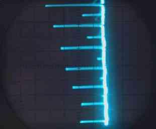
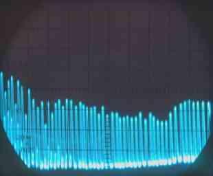
5 Frequency axis linearity Precise linarity of the frequency axis is hard to achieve in such as simple design. Any VCO using a varicap diode for tuning will exhibit some non-linearity. The reverse capacitance of varicaps is not linear with applied voltage, nor is the the VCO frequency linear with capacitance. Given these inherent limitations I am extremely surprised at the excellent linearity shown by this circuit. The photograph (right) shows the spectrum of the internal 10MHz crystal calibrator oscillator 5 / 10

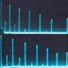
6 over the range 0-100MHz. Some non-linearity is visible at the right of the display but in general the linearity is very good. Always suspicious of my cheap 5Mhz Kenwood oscilloscope, I decided to try the same trace but swap the oscilloscope X and Y connections. Because of the scales of the voltages involved and the considerably lesser amplification available on the oscilloscope X input, the size of the peaks in this mode is smaller (see photo, left). The experiment shows that the frequency axis linearity is greatly improved. This means that much of the non-linearity visible in the normal trace is due to imperfections in the oscilloscope rather than true non-linearity in the spectrum analyser. To further illustrate this point and make a nice comparison - here's an experiment with the frequency linearity over the whole frequency coverage 0-140MHz. The photograph below left shows the spectrum from MHz of the 10MHz calibration oscillator. Below centre is the same trace, with the X and Y inputs swapped. Below right: the digitally remastered composite image. Here I used Microsoft PhotoEditor to remove the axis tilt and size the pictures to the same scale. The upper trace is the normal configuration, the lower half is the X-Y swapped version. Here it's clear to see that the linearity of the oscilloscope X axis is questionable. 6 / 10
7 7 / 10

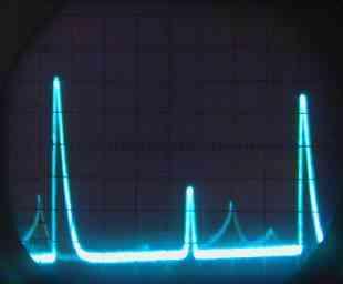
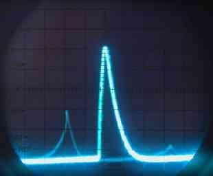
8 Other Oscilloscope problems You can't fail to have noticed the annoying upward slope of the baseline from left to right, in all the oscilloscope photographs. Is this a problem in the analyser or another 'scope defect? Quite possibly the response of circuits in the analyser could create this effect, indicating a design fault. Fortunately this one is easy to blame on the 'scope: the upward slope is present even when the spectrum analyser is disconnected. I am developing a new spectrum analyser which uses digital storage and a 4.5-inch television tube for the display. This photograph shows the display section of the new project, connected to the output of this spectrum analyser. The spectrum of the 10MHz calibration oscillator is being displayed, the frequency range is about 2-42 MHz. The baseline is perfectly horizontal against the digitally generated graticule. Some more screenshots Here's a few more examples. Left: 10MHz calibration oscillator spectrum, 8-32 MHz showing fundamental at 10MHz, with 2nd and 3rd harmonics. Note the very much reduced amplitude of the 2nd harmonic. In a perfect square wave oscillator there are no even-order harmonics. The output of the calibrator approximates a 10MHz square wave which is why the even harmonics are always much lower in these photographs. Centre: Closeup on the 10MHz peak, showing the shape of the 2nd IF filtering. Right: spectrum of my Heathkit signal generator tuned to approximately 1MHz. The even-order harmonics are of lower amplitude but still visible out to about 40MHz. 8 / 10
9 9 / 10
10 10 / 10
Automatic Tracking Filter for DDS Generator
 Riccardo Gionetti, IØFDH Via S. Bernadette, 00 Roma RM, Italy: rgionetti@virgilio.it Automatic Tracking Filter for DDS Generator Reduce spurious responses from a digital synthesizer with this filter. The
3.2 Measuring Frequency Response Of Low-Pass Filter :
 2.5 Filter Band-Width : In ideal Band-Pass Filters, the band-width is the frequency range in Hz where the magnitude response is at is maximum (or the attenuation is at its minimum) and constant and equal
Keywords: ISM, RF, transmitter, short-range, RFIC, switching power amplifier, ETSI
 Maxim > Design Support > Technical Documents > Application Notes > Wireless and RF > APP 4929 Keywords: ISM, RF, transmitter, short-range, RFIC, switching power amplifier, ETSI APPLICATION NOTE 4929 Adapting
HF Amateur SSB Receiver
 HF Amateur SSB Receiver PCB Set for radio club project http://rhelectronics.net PCB for DIY HF Amateur SSB Receiver 20M The receiver is a simple syperheterodyne type with quartz crystal filter. The circuit
CHAPTER 13 TRANSMITTERS AND RECEIVERS
 CHAPTER 13 TRANSMITTERS AND RECEIVERS Frequency Modulation (FM) Receiver Frequency Modulation (FM) Receiver FREQUENCY MODULATION (FM) RECEIVER Superheterodyne Receiver Heterodyning The word heterodyne
Kostas SV3ORA's triple crystal oscillator:
 Kostas SV3ORA informed me of his oscillator circuit which has a single J108 Field Effect Transistor and three crystals, oscillating all at the same time on their three different frequencies. His article
Swept-tuned spectrum analyzer. Gianfranco Miele, Ph.D
 Swept-tuned spectrum analyzer Gianfranco Miele, Ph.D www.eng.docente.unicas.it/gianfranco_miele g.miele@unicas.it Reference level and logarithmic amplifier The signal displayed on the instrument screen
Tuning a 160M full sized vertical with strong AM broadcast RF present on the antenna. Jay Terleski, WX0B
 Tuning a 160M full sized vertical with strong AM broadcast RF present on the antenna. Jay Terleski, WX0B I often get asked about how to match a ¼ WL vertical to a 50 ohm transmission line and what to do
ALX-SSB 5 Band Filter Assembly Manual 19 November 2018
 ALX-SSB 5 Band Filter Assembly Manual 19 November 2018 Contents Theory of Operation:... 1 Figure 1... 2 Parts Included:... 4 Board Overview:... 5 Figure 2... 5 Figure 3... 5 Board Assembly:... 6 Cable
Exercise 1: RF Stage, Mixer, and IF Filter
 SSB Reception Analog Communications Exercise 1: RF Stage, Mixer, and IF Filter EXERCISE OBJECTIVE DISCUSSION On the circuit board, you will set up the SSB transmitter to transmit a 1000 khz SSB signal
Receiver Design. Prof. Tzong-Lin Wu EMC Laboratory Department of Electrical Engineering National Taiwan University 2011/2/21
 Receiver Design Prof. Tzong-Lin Wu EMC Laboratory Department of Electrical Engineering National Taiwan University 2011/2/21 MW & RF Design / Prof. T. -L. Wu 1 The receiver mush be very sensitive to -110dBm
Homebrew and Experimenters Group HF Inductance Bridge (Compiled by VK2TOX)
") Homebrew and Experimenters Group HF Inductance Bridge (Compiled by VK2TOX) There are a number of ways to measure inductances used in construction of RF equipment. One of the most versatile ways is with
Homebrew and Experimenters Group HF Inductance Bridge (Compiled by VK2TOX) There are a number of ways to measure inductances used in construction of RF equipment. One of the most versatile ways is with
Laboratory Exercise 6 THE OSCILLOSCOPE
 Introduction Laboratory Exercise 6 THE OSCILLOSCOPE The aim of this exercise is to introduce you to the oscilloscope (often just called a scope), the most versatile and ubiquitous laboratory measuring
Chapter 3. Question Mar No
 Chapter 3 Sr Question Mar No k. 1 Write any two drawbacks of TRF radio receiver 1. Instability due to oscillatory nature of RF amplifier.. Variation in bandwidth over tuning range. 3. Insufficient selectivity
Technical Shorts. by Gerry O Hara, VE7GUH/G8GUH
 Technical Shorts by, VE7GUH/G8GUH Technical Shorts is a series of (fairly) short articles prepared for the Eddystone User Group (EUG) website, each focussing on a technical issue of relevance in repairing,
The G4EGQ RAE COURSE Lesson 9 Transmitters Lesson 8 looked at a simple transmitter exciter comprising of oscillator, buffer and multiplier stages.
 Lesson 8 looked at a simple transmitter exciter comprising of oscillator, buffer and multiplier stages. The power amplifier The output from the exciter is usually very low and it is necessary to amplify
MAHARASHTRA STATE BOARD OF TECHNICAL EDUCATION (Autonomous) (ISO/IEC Certified) SUMMER 14 EXAMINATION Model Answer
 (ISO/IEC Certified) SUMMER 14 EXAMINATION Model Answer") MAHARASHTRA STATE BOARD OF TECHNICAL EDUCATION (Autonomous) (ISO/IEC 27001 2005 Certified) SUMMER 14 EXAMINATION Model Answer Subject Code : 17317 Page No: 1 Important Instructions to examiners: 1) The
MAHARASHTRA STATE BOARD OF TECHNICAL EDUCATION (Autonomous) (ISO/IEC 27001 2005 Certified) SUMMER 14 EXAMINATION Model Answer Subject Code : 17317 Page No: 1 Important Instructions to examiners: 1) The
Lab Reference Manual. ECEN 326 Electronic Circuits. Texas A&M University Department of Electrical and Computer Engineering
 Lab Reference Manual ECEN 326 Electronic Circuits Texas A&M University Department of Electrical and Computer Engineering Contents 1. Circuit Analysis in PSpice 3 1.1 Transient and DC Analysis 3 1.2 Measuring
Understanding RF and Microwave Analysis Basics
 Understanding RF and Microwave Analysis Basics Kimberly Cassacia Product Line Brand Manager Keysight Technologies Agenda µw Analysis Basics Page 2 RF Signal Analyzer Overview & Basic Settings Overview
MARTIN - G8JNJ ECLECTIC AETHER - ADVENTURES WITH AMATEUR RADIO
 MARTIN - G8JNJ ECLECTIC AETHER - ADVENTURES WITH AMATEUR RADIO REDUCING RTL DONGLE INTERNAL SPURII AND NOISE SIGNALS I ve recently bought quite a few RTL DVB-T RTL 2832U / Rafael Micro R820T dongles to
10 GHz Microwave Link
 10 GHz Microwave Link Project Project Objectives System System Functionality Testing Testing Procedures Cautions and Warnings Problems Encountered Recommendations Conclusion PROJECT OBJECTIVES Implement
Glossary of VCO terms
 Glossary of VCO terms VOLTAGE CONTROLLED OSCILLATOR (VCO): This is an oscillator designed so the output frequency can be changed by applying a voltage to its control port or tuning port. FREQUENCY TUNING
Definitions. Spectrum Analyzer
 SIGNAL ANALYZERS Spectrum Analyzer Definitions A spectrum analyzer measures the magnitude of an input signal versus frequency within the full frequency range of the instrument. The primary use is to measure
Keysight Measuring High Impedance Sources Using the U8903B Audio Analyzer. Application Note
 Keysight Measuring High Impedance Sources Using the U8903B Audio Analyzer Application Note Introduction This note details the input impedance of the U8903B Audio Analyzer, and shows that this needs to
Lab 4. Crystal Oscillator
 Lab 4. Crystal Oscillator Modeling the Piezo Electric Quartz Crystal Most oscillators employed for RF and microwave applications use a resonator to set the frequency of oscillation. It is desirable to
A.C. FILTER NETWORKS. Learning Objectives
 C H A P T E 17 Learning Objectives Introduction Applications Different Types of Filters Octaves and Decades of Frequency Decibel System alue of 1 db Low-Pass C Filter Other Types of Low-Pass Filters Low-Pass
2m Weak Signal Sources January 2018
 2m Weak Signal Sources January 2018 Rick Campbell This white paper describes a set of signal sources at power levels from -30dBm to +12dBm in the 144 MHz amateur radio band. All are legal for direct connection
HF PA kit with built-in standalone raised cosine controller
 AN005 HF PA kit with built-in standalone raised cosine controller 1. Introduction The standard QRP Labs HF PA kit has an 8-bit shift register (74HC595) whose outputs control an 8- bit Digital-to-Analogue
PN9000 PULSED CARRIER MEASUREMENTS
 The specialist of Phase noise Measurements PN9000 PULSED CARRIER MEASUREMENTS Carrier frequency: 2.7 GHz - PRF: 5 khz Duty cycle: 1% Page 1 / 12 Introduction When measuring a pulse modulated signal the
Module 8 Theory. dbs AM Detector Ring Modulator Receiver Chain. Functional Blocks Parameters. IRTS Region 4
 Module 8 Theory dbs AM Detector Ring Modulator Receiver Chain Functional Blocks Parameters Decibel (db) The term db or decibel is a relative unit of measurement used frequently in electronic communications
8 Hints for Better Spectrum Analysis. Application Note
 8 Hints for Better Spectrum Analysis Application Note 1286-1 The Spectrum Analyzer The spectrum analyzer, like an oscilloscope, is a basic tool used for observing signals. Where the oscilloscope provides
Exam Booklet. Pulse Circuits
 Exam Booklet Pulse Circuits Pulse Circuits STUDY ASSIGNMENT This booklet contains two examinations for the six lessons entitled Pulse Circuits. The material is intended to provide the last training sought
FREQUENCY AGILE FM MODULATOR INSTRUCTION BOOK IB
 FMT615C FREQUENCY AGILE FM MODULATOR INSTRUCTION BOOK IB1215-02 TABLE OF CONTENTS SECTION SUBJECT 1.0 Introduction 2.0 Installation & Operating Instructions 3.0 Specification 4.0 Functional Description
EVALUATION KIT AVAILABLE 10MHz to 1050MHz Integrated RF Oscillator with Buffered Outputs. Typical Operating Circuit. 10nH 1000pF MAX2620 BIAS SUPPLY
 19-1248; Rev 1; 5/98 EVALUATION KIT AVAILABLE 10MHz to 1050MHz Integrated General Description The combines a low-noise oscillator with two output buffers in a low-cost, plastic surface-mount, ultra-small
Single Conversion LF Upconverter Andy Talbot G4JNT Jan 2009
 Single Conversion LF Upconverter Andy Talbot G4JNT Jan 2009 Mark 2 Version Oct 2010, see Appendix, Page 8 This upconverter is designed to directly translate the output from a soundcard from a PC running
Some Thoughts on Electronic T/R Circuits
 Some Thoughts on Electronic T/R Circuits Wes Hayward, w7zoi, November 3, 2018 Abstract: Several schemes have been used to switch an antenna between a receiver and transmitter. A popular scheme with low
THE 1956 ZENITH ROYAL 500 TRANSISTOR OWL S EYES RADIO.
 THE 1956 ZENITH ROYAL 500 TRANSISTOR OWL S EYES RADIO. Dr. H. Holden. Feb. 2018. Introduction: The Zenith Royal 500 radio appeared in 1956, two years later than the Regency TR1 which was the first commercial
UNIT-3. Electronic Measurements & Instrumentation
 UNIT-3 1. Draw the Block Schematic of AF Wave analyzer and explain its principle and Working? ANS: The wave analyzer consists of a very narrow pass-band filter section which can Be tuned to a particular
Fourier Theory & Practice, Part II: Practice Operating the Agilent Series Scope with Measurement/Storage Module
 Fourier Theory & Practice, Part II: Practice Operating the Agilent 54600 Series Scope with Measurement/Storage Module By: Robert Witte Agilent Technologies Introduction: This product note provides a brief
A Walk Through the MSA Software Vector Network Analyzer Transmission Mode 12/18/09
 A Walk Through the MSA Software Vector Network Analyzer Transmission Mode 12/18/09 This document is intended to familiarize you with the basic features of the MSA and its software, operating as a Vector
Chapter 6. FM Circuits
 Chapter 6 FM Circuits Topics Covered 6-1: Frequency Modulators 6-2: Frequency Demodulators Objectives You should be able to: Explain the operation of an FM modulators and demodulators. Compare and contrast;
Technical Notes from Laplace Instruments Ltd. EMC Emissions measurement. Pre selectors... what, why and when?
 Technical Notes from Laplace Instruments Ltd EMC Emissions measurement. Pre selectors... what, why and when? Most of us working in EMC will have heard comments about pre-selectors. This article sets out
WESTREX RA-1712 PHOTOGRAPHIC SOUND RECORD ELECTRONICS
 INTRODUCTION The RA-1712 solid state Record Electronics is an integrated system for recording photographic sound tracks on a Westrex photographic sound recorder. It accepts a 600Ω input signal level from
A Guide to Calibrating Your Spectrum Analyzer
 A Guide to Calibrating Your Application Note Introduction As a technician or engineer who works with electronics, you rely on your spectrum analyzer to verify that the devices you design, manufacture,
Measuring Non-linear Amplifiers
 Measuring Non-linear Amplifiers Transceiver Components & Measuring Techniques MM3 Jan Hvolgaard Mikkelsen Radio Frequency Integrated Systems and Circuits Division Aalborg University 27 Agenda Non-linear
8 Hints for Better Spectrum Analysis. Application Note
 8 Hints for Better Spectrum Analysis Application Note 1286-1 The Spectrum Analyzer The spectrum analyzer, like an oscilloscope, is a basic tool used for observing signals. Where the oscilloscope provides
HF Receivers, Part 2
 HF Receivers, Part 2 Superhet building blocks: AM, SSB/CW, FM receivers Adam Farson VA7OJ View an excellent tutorial on receivers NSARC HF Operators HF Receivers 2 1 The RF Amplifier (Preamp)! Typical
Application Note Receivers MLX71120/21 With LNA1-SAW-LNA2 configuration
 Designing with MLX71120 and MLX71121 receivers using a SAW filter between LNA1 and LNA2 Scope Many receiver applications, especially those for automotive keyless entry systems require good sensitivity
Radio Receivers. Al Penney VO1NO
 Radio Receivers Role of the Receiver The Antenna must capture the radio wave. The desired frequency must be selected from all the EM waves captured by the antenna. The selected signal is usually very weak
A 3 TO 30 MHZ HIGH-RESOLUTION SYNTHESIZER CONSISTING OF A DDS, DIVIDE-AND-MIX MODULES, AND A M/N SYNTHESIZER. Richard K. Karlquist
 A 3 TO 30 MHZ HIGH-RESOLUTION SYNTHESIZER CONSISTING OF A DDS, -AND-MIX MODULES, AND A M/N SYNTHESIZER Richard K. Karlquist Hewlett-Packard Laboratories 3500 Deer Creek Rd., MS 26M-3 Palo Alto, CA 94303-1392
ANALOG COMMUNICATION
 ANALOG COMMUNICATION TRAINING LAB Analog Communication Training Lab consists of six kits, one each for Modulation (ACL-01), Demodulation (ACL-02), Modulation (ACL-03), Demodulation (ACL-04), Noise power
Experiment 1: Instrument Familiarization (8/28/06)
") Electrical Measurement Issues Experiment 1: Instrument Familiarization (8/28/06) Electrical measurements are only as meaningful as the quality of the measurement techniques and the instrumentation applied
Electrical Measurement Issues Experiment 1: Instrument Familiarization (8/28/06) Electrical measurements are only as meaningful as the quality of the measurement techniques and the instrumentation applied
10MHz to 1050MHz Integrated RF Oscillator with Buffered Outputs
 9-24; Rev 2; 2/02 EVALUATION KIT AVAILABLE 0MHz to 050MHz Integrated General Description The combines a low-noise oscillator with two output buffers in a low-cost, plastic surface-mount, ultra-small µmax
2-Tone Generator For 145Mhz
 Wolfgang Schneider, DJ8ES 2-Tone Generator For 145Mhz An RF amplifier stage is not only classified by amplification, which is as high as possible, and thus by its maximum output. What is frequently not
Experiment 1: Instrument Familiarization
 Electrical Measurement Issues Experiment 1: Instrument Familiarization Electrical measurements are only as meaningful as the quality of the measurement techniques and the instrumentation applied to the
Definitions of Technical Terms
 Definitions of Technical Terms Terms Ammeter Amperes, Amps Band Capacitor Carrier Squelch Diode Dipole Definitions How is an ammeter usually connected = In series with the circuit What instrument is used
N3ZI Kits General Coverage Receiver, Assembly & Operations Manual (For Jun 2011 PCB ) Version 3.33, Jan 2012
 Version 3.33, Jan 2012") N3ZI Kits General Coverage Receiver, Assembly & Operations Manual (For Jun 2011 PCB ) Version 3.33, Jan 2012 Thank you for purchasing my general coverage receiver kit. You can use the photo above as a
N3ZI Kits General Coverage Receiver, Assembly & Operations Manual (For Jun 2011 PCB ) Version 3.33, Jan 2012 Thank you for purchasing my general coverage receiver kit. You can use the photo above as a
Optical Pumping Control Unit
 (Advanced) Experimental Physics V85.0112/G85.2075 Optical Pumping Control Unit Fall, 2012 10/16/2012 Introduction This document is gives an overview of the optical pumping control unit. Magnetic Fields
Building a Bitx20 Version 3
 Building a Bitx20 Version 3 The board can be broken into sections and then built and tested one section at a time. This will make troubleshooting easier as any problems will be confined to one small section.
ericssonz LBI-38640E MAINTENANCE MANUAL FOR VHF TRANSMITTER SYNTHESIZER MODULE 19D902780G1 DESCRIPTION
 MAINTENANCE MANUAL FOR VHF TRANSMITTER SYNTHESIZER MODULE 19D902780G1 TABLE OF CONTENTS Page DESCRIPTION........................................... Front Cover GENERAL SPECIFICATIONS...................................
Spectrum analyzer for frequency bands of 8-12, and MHz
 EE389 Electronic Design Lab Project Report, EE Dept, IIT Bombay, November 2006 Spectrum analyzer for frequency bands of 8-12, 12-16 and 16-20 MHz Group No. D-13 Paras Choudhary (03d07012)
4. Digital Measurement of Electrical Quantities
 4.1. Concept of Digital Systems Concept A digital system is a combination of devices designed for manipulating physical quantities or information represented in digital from, i.e. they can take only discrete
Introduction. In the frequency domain, complex signals are separated into their frequency components, and the level at each frequency is displayed
 SPECTRUM ANALYZER Introduction A spectrum analyzer measures the amplitude of an input signal versus frequency within the full frequency range of the instrument The spectrum analyzer is to the frequency
Measurement of the equivalent circuit of quartz crystals
 Measurement of the equivalent circuit of quartz crystals This application note shows how to measure the equivalent circuit of a quartz crystal with Bode 100. A.) Basics: An equivalent describtion of a
Application Note SAW-Components
 Application Note SAW-Components Comparison between negative impedance oscillator (Colpitz oscillator) and feedback oscillator (Pierce structure) App.: Note #13 Author: Alexander Glas EPCOS AG Updated:
Rigol DSA705 Spectrum Analyzer Reviewed by Phil Salas AD5X
 Rigol DSA705 Spectrum Analyzer Reviewed by Phil Salas AD5X ad5x@arrl.net Today s state-of-the-art test equipment is becoming more and more affordable. Spectrum analyzers, however, have stayed above the
THE AMAZING BARLOW WADLEY XCR-30 CRYSTAL CONTROLLED 30 BAND TRANSISTOR RADIO. (A method to set the AGC) H. Holden, 2018.
 H. Holden, 2018.") THE AMAZING BARLOW WADLEY XCR-30 CRYSTAL CONTROLLED 30 BAND TRANSISTOR RADIO. (A method to set the AGC) H. Holden, 2018. Introduction: The Barlow Wadley XCR-30 radio is well known to amateur radio enthusiasts
THE AMAZING BARLOW WADLEY XCR-30 CRYSTAL CONTROLLED 30 BAND TRANSISTOR RADIO. (A method to set the AGC) H. Holden, 2018. Introduction: The Barlow Wadley XCR-30 radio is well known to amateur radio enthusiasts
Lab 4. Crystal Oscillator
 Lab 4. Crystal Oscillator Modeling the Piezo Electric Quartz Crystal Most oscillators employed for RF and microwave applications use a resonator to set the frequency of oscillation. It is desirable to
note application Measurement of Frequency Stability and Phase Noise by David Owen
 application Measurement of Frequency Stability and Phase Noise note by David Owen The stability of an RF source is often a critical parameter for many applications. Performance varies considerably with
100 Hz to 22. HP 8566B Spectrum Analyzer. Discontinued Product Support Information Only. Outstanding Precision and Capability
 Discontinued Product Support Information Only This literature was published years prior to the establishment of Agilent Technologies as a company independent from Hewlett-Packard and describes products
EFFECT OF INTEGRATION ERROR ON PARTIAL DISCHARGE MEASUREMENTS ON CAST RESIN TRANSFORMERS. C. Ceretta, R. Gobbo, G. Pesavento
 Sept. 22-24, 28, Florence, Italy EFFECT OF INTEGRATION ERROR ON PARTIAL DISCHARGE MEASUREMENTS ON CAST RESIN TRANSFORMERS C. Ceretta, R. Gobbo, G. Pesavento Dept. of Electrical Engineering University of
7. Transmitter Radiated Spurious Emissions and Conducted Spurious Emission
 7. Transmitter Radiated Spurious Emissions and Conducted Spurious Emission 7.1 Test Setup Refer to the APPENDIX I. 7.2 Limit According to 15.247(d), in any 100 khz bandwidth outside the frequency band
Applications Note RF Transmitter and Antenna Design Hints
 This application note covers the TH7107,TH71071,TH71072,TH7108,TH71081,TH72011,TH72031,TH7204 Single Frequency Transmitters. These transmitters have different features and cover different bands but they
RFID Systems: Radio Architecture
 RFID Systems: Radio Architecture 1 A discussion of radio architecture and RFID. What are the critical pieces? Familiarity with how radio and especially RFID radios are designed will allow you to make correct
The ROSE 80 CW Transceiver (Part 1 of 3)
") Build a 5 watt, 80 meter QRP CW Transceiver!!! Page 1 of 10 The ROSE 80 CW Transceiver (Part 1 of 3) Build a 5 watt, 80 meter QRP CW Transceiver!!! (Designed by N1HFX) A great deal of interest has been
Build a 5 watt, 80 meter QRP CW Transceiver!!! Page 1 of 10 The ROSE 80 CW Transceiver (Part 1 of 3) Build a 5 watt, 80 meter QRP CW Transceiver!!! (Designed by N1HFX) A great deal of interest has been
1, Bandwidth (Hz) ,
 ,") A Crystal Filter Tutorial Abstract: The general topic of crystal filters will be discussed in a manner that is intended to help the user to better understand, specify, test, and use them. The center frequency
A Crystal Filter Tutorial Abstract: The general topic of crystal filters will be discussed in a manner that is intended to help the user to better understand, specify, test, and use them. The center frequency
CAVITY TUNING. July written by Gary Moore Telewave, Inc. 660 Giguere Court, San Jose, CA Phone:
 CAVITY TUNING July 2017 -written by Gary Moore Telewave, Inc 660 Giguere Court, San Jose, CA 95133 Phone: 408-929-4400 1 P a g e Introduction Resonant coaxial cavities are the building blocks of modern
MAINTENANCE MANUAL RF BOARD 19D901835G1 ( MHz) 19D901835G2 ( MHz) FOR MVS
 19D901835G2 ( MHz) FOR MVS") D MAINTENANCE MANUAL F BOAD 19D901835G1 (136-153 MHz) 19D901835G2 (150-174 MHz) FO MVS TABLE OF CONTENTS DESCIPTION............................................... Front Cover CICUIT ANALYSIS..............................................
D MAINTENANCE MANUAL F BOAD 19D901835G1 (136-153 MHz) 19D901835G2 (150-174 MHz) FO MVS TABLE OF CONTENTS DESCIPTION............................................... Front Cover CICUIT ANALYSIS..............................................
The Active Bridge 11/20/09
 The Active Bridge 11/20/09 The Active Bridge is an op-amp based reflection bridge that produces an output proportional to the signal reflected by an attached device under test (DUT). It can therefore be
HOMEBREW Q-MULTIPLIER
 HOMEBREW Q-MULTIPLIER This circuit can boost the signal strength in your receiver by 1 or 2 S-units, giving approximately 10 db gain. A Q-multiplier amplifies the Q of the first IF transformer so that
USER. manual. Falco Systems WMA-100. High Voltage Amplifier DC - 500kHz
 USER manual Falco Systems WMA-100 High Voltage Amplifier DC - 500kHz Falco Systems WMA-100, High Voltage Amplifier DC - 500kHz High voltage: 20x amplification up to +175V and -175V output voltage with
Lecture 16 Microwave Detector and Switching Diodes
 Basic Building Blocks of Microwave Engineering Prof. Amitabha Bhattacharya Department of Electronics and Communication Engineering Indian Institute of Technology, Kharagpur Lecture 16 Microwave Detector
Tuned circuits. Introduction - Tuned Circuits
 Tuned circuits Introduction - Tuned Circuits Many communication applications use tuned circuits. These circuits are assembled from passive components (that is, they require no power supply) in such a way
Lab 10: Oscillators (version 1.1)
") Lab 10: Oscillators (version 1.1) WARNING: Use electrical test equipment with care! Always double-check connections before applying power. Look for short circuits, which can quickly destroy expensive equipment.
Lab 10: Oscillators (version 1.1) WARNING: Use electrical test equipment with care! Always double-check connections before applying power. Look for short circuits, which can quickly destroy expensive equipment.
1 FUNCTIONAL DESCRIPTION WAY SPLITTER/INPUT BOARD FET RF AMPLIFIERS WAY POWER COMBINER VSWR CONTROL BOARD...
 CONTENTS 1 FUNCTIONAL DESCRIPTION...1 2 4-WAY SPLITTER/INPUT BOARD...2 3 FET RF AMPLIFIERS...3 4 4-WAY POWER COMBINER...4 5 VSWR CONTROL BOARD...5 6 ADJUSTMENT OF BIAS VOLTAGE TO ESTABLISH PROPER QUIESCENT
Electrical Fundamentals and Basic Components Chapters T2, T3, G4
 Electrical Fundamentals and Basic Components Chapters T2, T3, G4 Some Basic Math, Electrical Fundamentals, AC Power, The Basics of Basic Components, A Little More Component Detail, Reactance and Impedance
Fabricate a 2.4-GHz fractional-n synthesizer
 University of Malaya From the SelectedWorks of Professor Mahmoud Moghavvemi Summer June, 2013 Fabricate a 2.4-GHz fractional-n synthesizer H Ameri Mahmoud Moghavvemi, University of Malaya a Attaran Available
Technical Bulletin A Versatile Pulse Tester Page 1 of 6
 Technical Bulletin A Versatile Pulse Tester Page 1 of 6 A Versatile Pulse Tester By G8MNY (BATC's CQTV No 195, Updated Oct 07) (8 Bit ASCII Graphics use code page 437 or 850) This tester based on ideas
FMC664CC FM BAND CONVERTER
 FMC664CC FM BAND CONVERTER INSTRUCTION BOOK IB6225/6226-01 COPYRIGHT 1995 ALL RIGHTS RESERVED NO PART OF THIS BOOK MAY BE REPRODUCED OR UTILIZED IN ANY FORM OR BY ANY MEANS, ELECTRONIC OR MECHANICAL, INCLUDING
A year and a half after the first introduction of the PXA, Agilent is now introducing the world s highest performance mmw signal analyzer in April
 1 This presentation is intended to be a beginning tutorial on signal analysis. Vector signal analysis includes but is not restricted to spectrum analysis. It is written for those who are unfamiliar with
ATUs - ANTENNA TUNING UNITS THE ATU. An Antenna Tuning Unit MAKE YOUR OWN ATU
 ATUs - ANTENNA TUNING UNITS THE ATU An Antenna Tuning Unit MAKE YOUR OWN ATU The circuit diagram below shows the circuit for a typical Pi type ATU which seems to be a popular arrange ment for many ATUs.
A COMPACT, AGILE, LOW-PHASE-NOISE FREQUENCY SOURCE WITH AM, FM AND PULSE MODULATION CAPABILITIES
 A COMPACT, AGILE, LOW-PHASE-NOISE FREQUENCY SOURCE WITH AM, FM AND PULSE MODULATION CAPABILITIES Alexander Chenakin Phase Matrix, Inc. 109 Bonaventura Drive San Jose, CA 95134, USA achenakin@phasematrix.com
Using the V5.x Integrator
 Using the V5.x Integrator This document explains how to produce the Bode plots for an electromagnetic guitar pickup using the V5.x Integrator. Equipment: Test coil 50-100 turns of 26 AWG coated copper
Copyright 2012, R. Eckweiler & OCARC, Inc. Page 1 of 5
 Heathkit of the Month #42: by Bob Eckweiler, AF6C Heathkit HD-1422-A Antenna Noise Bridge Introduction: If you work with antennas, an antenna noise bridge can be a very handy tool. Table 1 lists some of
Chapter 2. The Fundamentals of Electronics: A Review
 Chapter 2 The Fundamentals of Electronics: A Review Topics Covered 2-1: Gain, Attenuation, and Decibels 2-2: Tuned Circuits 2-3: Filters 2-4: Fourier Theory 2-1: Gain, Attenuation, and Decibels Most circuits
Beta-test ED1 PCB installed in I0CG s K1
 K1 SSB Modification (Ed.2) This description provides the receiver (RX) modifications, assembly, alignment and operation as a first step. In a second step you can add the remaining transmitter (TX) modifications,
But this is about practical experiments so lets find out what an inductor is all about.
 Chapter 2 inductors Inductors are components we often use in radio design. We measure them with our LCR meter and build a circuit with them, only to find out the resonance is way off from the calculated
Knight Kit V44 VFO Stabilized by the Cumbria Design X-Lock 3.0
 Knight Kit V44 VFO Stabilized by the Cumbria Design X-Lock 3.0 The Knight V44 VFO has a place in history. It was designed in the late 1950 s as a self contained VFO intended to plug into the crystal socket
An Introduction to Spectrum Analyzer. An Introduction to Spectrum Analyzer
 1 An Introduction to Spectrum Analyzer 2 Chapter 1. Introduction As a result of rapidly advancement in communication technology, all the mobile technology of applications has significantly and profoundly
Experiment No. 2 Pre-Lab Signal Mixing and Amplitude Modulation
 Experiment No. 2 Pre-Lab Signal Mixing and Amplitude Modulation Read the information presented in this pre-lab and answer the questions given. Submit the answers to your lab instructor before the experimental