TLN-428 Voltage Controlled State Variable Filter
|
|
|
- Marilynn Newman
- 5 years ago
- Views:
Transcription
1 The Tellun Corporation TLN-428 Voltage Controlled State Variable Filter User Guide, Rev. 1.1 Scott Juskiw The Tellun Corporation TLN-428 User Guide Revision 1.1 March 16, 2003
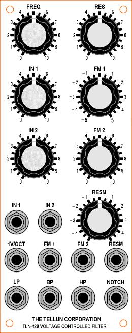
2 Introduction The TLN-428 is a state variable filter built around a Curtis Electromusic Specialties CEM 3320 chip. Four simultaneous outputs (all with two pole response) are provided: low pass, high pass, band pass, and notch. A built in mixer allows for two audio inputs. The filter frequency can be set using a panel mounted pot, a one volt per octave external control voltage, or via two external FM inputs with attenuators (one reversing). Filter resonance can be set using a panel mounted pot or an external control voltage with a reversing attenuator. Circuit Description A state variable filter comprises a summing amp and two integrators to create low pass, high pass, and band pass outputs simultaneously. The low pass and high pass outputs are typically combined with a summing amp to provide a notch output. The CEM 3320 provides four gain cell blocks that can be configured into a variety of filters. The TLN- 428 uses two of the CEM 3320 gain cell blocks as integrators. A third gain cell block is used as a summing amp and allows use of the onboard Resonance Control Cell for voltage controlled resonance. The CEM 3320 application notes suggest using the fourth gain cell block as a summing amp for the notch output. However, this was not found to be a particularly stable approach and thus an external op amp is used to provide the notch output from the low pass and high pass outputs. The fourth gain cell block is not used in the TLN-428. Refer to page 3 of the schematic for the following discussion on the filter design. C13 and C14 are bypass caps for the power supply. R38 and TP2 limit the negative supply current and allow trimming the frequency control voltage feed through (see the Calibration section). The summing amp comprises R40 and gain cell block G1-C1-B1. The first integrator comprises R42, C23, and gain cell block G2-C2-B2. The second integrator comprises R23, C24, and gain cell block G3-C3-B3. The audio input signal is fed to the summing amp through R39. The low pass output is fed back to the summing amp through R41 and R25. The band pass output is fed back to the summing amp via C16 and then through two parallel paths, R26 and R27, in order to make use of the onboard Resonance Control Cell. C21 provides phase compensation to prevent the filter from honking too much at high resonance settings. C22 eliminates high frequency oscillations that creep into the high pass output at very low resonance settings. Refer to page 2 of the schematic for the following discussion on the output design. All four filter outputs are non-inverting with respect to the input signal. This is intentional as it allows any of the four outputs to be fed back to the filter input to further enhance the filter effect. The low pass output is AC coupled through C17 and then fed to a noninverting amplifier with a gain of one. Similarly, the high pass output is AC coupled through C18 and then fed to a non-inverting amplifier with a gain of one. The band pass output is AC coupled through C16 (on page 3 of the schematic) and then fed to an 1
3 inverting amplifier with a gain of one. The notch output is achieved by combining the low pass and high pass outputs with an inverting summing amp set for unity gain and then feeding this combined signal to another inverting amplifier with a gain of one. Refer to page 1 of the schematic for the following discussion on the input design. The two audio signals appearing at IN1 and IN2 are attenuated by VR6 and VR7 before being mixed by an inverting amplifier with a gain of one. This signal is then AC coupled to the filter via C15. Filter resonance is set either manually via VR1, or externally via the RESM input and VR2 through a reversing attenuator built around U1. Filter frequency can be set manually using VR5, externally via the 1V/OCT input, externally via the FM2 input and attenuator VR3, or externally via the FM1 input and a reversing attenuator built around U2. R10, TP1, and R15 derive an 18 mv/octave frequency control voltage from these combined controls and input signals (see the Calibration section). Construction Tips Use a socket for the CEM 3320; this is a rare and expensive chip. Sockets are not necessary for the other chips. Coax cable should be used for the two audio input signals (J5 and J6) and the four audio output signals (J7, J8, J9, J10). Consider using two-conductor coax (microphone cable) for connecting the two audio input attenuators (VR6, VR7). R15 is a Tempco resistor and must be mounted on top of the CEM 3320 chip. Use a dab of heat sink compound to thermally connect R15 to the CEM R15 should be the last component installed on the PCB. The PCB uses 0.4 spacing for the resistor pads and 0.2 spacing for most of the capacitor pads. The exceptions being C23 and C24 (axially mounted polystyrene caps) which have a 0.6 pad spacing. Save some scrap resistor leads and use them to connect the switching lug of the phone jacks to ground for the inputs (J1-J6). R43 and R45 are infinite ohm resistors, i.e. an open circuit, so don t install anything there. R44 and R46 are zero ohm resistors, i.e. a short circuit, so install a wire jumper there (a scrap resistor lead will work fine). Space is left on the PCB for installing resistors in these locations in order to change the gain of the LP and HP outputs. See the Modifications section for details. 2
4 Panel Wiring Guide Panel Designation PCB Designation Wire Length (inches) Wire Type RES pot VR1 2 twisted RESM pot VR2 5 twisted FM 2 pot VR3 3 twisted FM 1 pot VR4 2 twisted FREQ pot VR5 4 twisted IN 1 pot VR6 4 coax or twisted IN 2 pot VR7 4 coax or twisted RESM jack J1 8 twisted 1V/OCT jack J2 7 twisted FM 2 jack J3 6 twisted FM 1 jack J4 6 twisted IN 1 jack J5 5 coax IN 2 jack J6 4 coax LP jack J7 5 coax HP jack J8 5 coax BP jack J9 5 coax NOTCH jack J10 4 coax For VR1-VR7, the square pad on the PCB indicates pin 1, the middle pad is pin 2, and the remaining pad is pin 3. The pin out for most pots is (left to right): 3, 2, 1 when viewing the back of the pot with the leads facing down. For J1-J10, the square pad on the PCB indicates the ground connection. Calibration Let the filter warm up for a few minutes before attempting calibration. TP1 sets the filter s one volt per octave tracking. Disconnect any signals from the FM1, FM2, IN1, IN2, and RESM inputs. Set TP1 to the middle of its range. Set the RES control fully clockwise to get the filter to oscillate. Set the FREQ control to the 2 position. Alternately apply and volts to the 1V/OCT input and adjust TP1 until the filter pitch is two octaves apart at these two voltages. Use a frequency counter or a calibrated reference oscillator for comparison. Don t adjust the FREQ knob on the TLN-428 while setting TP1, adjust the frequency of the reference oscillator instead. Don t worry about trying to get the filter to track perfectly over a wide range; it s just a filter, it s not an oscillator. TP2 sets the frequency input control voltage rejection. Disconnect any signals from the FM1, FM2, IN1, IN2, and RESM inputs. Set TP2 to the middle of its range. Set the FREQ and RES controls fully counter clockwise. Apply a sawtooth waveform from an oscillator into the 1V/OCT input. The oscillator should be in the audible range. Adjust TP2 for the minimum output signal. Use an oscilloscope or listen to the output. 3
5 Modifications TL072 op amps can be used instead of the MXL1013 and OP275GP op amps. C21 provides phase compensation to prevent the filter from honking too much at high resonance settings. C22 eliminates high frequency oscillations that creep into the high pass output at very low resonance settings. Both values can be changed to increase or decrease the maximum amount of resonance that the filter can achieve before going into oscillation. Lowering C21 and C22 allows higher resonance to be achieved but increases the risk of high frequency oscillation. Increasing C21 and C22 results in a more stable filter but lowers the maximum resonance achievable. In general, C21 needs to be about twice as large as C22 to keep the filter stable. The FM2 input has a gain of 2.0 but the FM1 input only has a gain of To get a gain of 2.0 with the FM1 input, lower R17 and R18 from 49.9K to 36K. However, this will also lower the input impedance on the FM1 input accordingly. R11 and R12 can be tweaked to change the filter frequency response. R11 sets the filter frequency when the FREQ knob is at minimum (fully CCW). Increasing the value of R11 will raise the filter frequency when the FREQ knob is at minimum. R12 sets the filter frequency when the FREQ knob is at the maximum (fully CW). Decreasing R12 will decrease the filter frequency when the FREQ knob is at maximum. Note that R11 should always be adjusted before R12 because R11 affects both the minimum and maximum frequency. Thus, changing R11 will likely require changing R12 as well. R27 sets the point where the filter will oscillate. The suggested value of 240K will allow the filter to oscillate when the RES control is at the 8 position. The filter oscillates more easily at higher frequencies. Lowering R27 will allow the filter to oscillate at a lower RES control setting. R27 can be increased to prevent the filter from oscillating at any RES control setting. The input and output amplifiers are designed to provide unity gain through the filter. This should provide sufficient output drive. More gain can be achieved by changing a few resistors. Be warned that when the filter oscillates, it will output a 12 Vpp signal at unity gain; increasing the gain will provide an even larger output signal. Decrease R29 to get more gain out of the BP output; the gain equation is R30/R29. Decrease R32 to get more gain out of the NOTCH output; the gain equation is R31/R32. Put resistors in for R43 and R44 to get more gain out of the LP output; the gain equation is 1 + R44/R43. Put resistors in for R45 and R46 to get more gain out of the HP output; the gain equation is 1 + R46/R45. 4
6 TLN-428 Parts List Resistors K R20, R21, R22, R23, R29, R30, 5% or better, Mouser # K R31, R32, R33, R35, R37, R40, R K R24, R28, R34, R36 5% or better, Mouser #291-1K 2 91 K R39, R41 5% or better, Mouser #291-91K K R26 5% or better, Mouser # K K R25, R27 5% or better, Mouser # K ohm R38 5% or better, Mouser # M R8 5% or better, Mouser # M K R5 1%, Mouser # K K R1, R2, R3, R4, R9, R14, R16, 1%, Mouser # K R K R6, R7, R13, R17, R18 1%, Mouser # K K R10 1%, Mouser # K 1 1 K R15 1% Tempco, PT146 or similar K R11 1%, Mouser # K K R12 1%, Mouser # K 2 infinite ohm R43, R45 see Construction Tips and Modifications 2 zero ohm R44, R46 see Construction Tips and Modifications Capacitors uf 35V electrolytic C15, C16, C17, C18 can substitute 3.3 uf, or use bipolar, Mouser #140-XRL35V pf ceramic C19, C20 can substitute 22 pf, Mouser #140-50N5-330J 1 18 pf ceramic C21 Mouser #140-50N5-180J 1 10 pf ceramic C22 Mouser #140-50N5-100J pf polystyrene C23, C24 axial lead, Mouser #23PS uf ceramic C3 C14 Mouser # uf 25V electrolytic C1, C2 can use 35V, Mouser #140-XRL25V22 Semiconductors 2 MXL1013 (or LT1013) dual op amp U1, U2 can substitute TL072, Allied # OP275GP dual op amp U3, U4, U5 can substitute TL072, Allied # CEM 3320 filter U6 5
7 Potentiometers & Trimmers K log pot VR6, VR7 Bournes 91 series, Allied # K linear pot VR1, VR2, VR3, VR4, VR5 Spectrol 149 series, Allied # , or Bournes 91 series, Allied # K trimmer (multiturn) TP1 Mouser #72-T93YA-25K 1 1 K trimmer (multiturn) TP2 Mouser #72-T93YA-1K Miscellaneous 10 phone jack J1 J10 Switchcraft 112A, Allied # pin DIP socket for U6 5 8 pin DIP socket for U1 U5 (optional) 2 axial ferrite beads L1, L2 Active #MURJP2141, or Mouser # MTA-156 power connector JP1 Mouser # Hardware Quantity Description Notes 7 knobs ALCO PKES90B1/4 1 TLN-428 panel front panel 1 TLN-428 pcb printed circuit board 1 4 pot short Stooge bracket Stooge bracket 4 #6-32 screw, spacer, and nut for mounting circuit board to Stooge bracket 4 pot nut for mounting Stooge bracket to front panel 4 #8-32 black screw for mounting module to cabinet 1 power cable with MTA-156 connectors heat shrink cable wire ties coax cable hookup wire solder both organic and no clean heat sink compound 6
8
9
The Tellun Corporation. TLN-442 Voltage Controlled Lowpass Filter. User Guide, Rev Scott Juskiw The Tellun Corporation
 The Tellun Corporation TLN-442 Voltage Controlled Lowpass Filter User Guide, Rev. 1.1 Scott Juskiw The Tellun Corporation scott@tellun.com TLN-442 User Guide Revision 1.1 March 15, 2003 Introduction The
The Tellun Corporation. TLN-861 Dunsel. User Guide, Rev Scott Juskiw The Tellun Corporation
 The Tellun Corporation TLN-861 Dunsel User Guide, Rev. 1.0 Scott Juskiw The Tellun Corporation scott@tellun.com TLN-861 User Guide Revision 1.0 August 31, 2006 1. Introduction The TLN-861 Dunsel is a collection
The Tellun Corporation. TLN-863 Max Min Generator. User Guide, Rev Scott Juskiw The Tellun Corporation
 The Tellun Corporation TLN-863 Max Min Generator User Guide, Rev. 1.1 Scott Juskiw The Tellun Corporation scott@tellun.com TLN-863 User Guide Revision 1.1 May 26, 2008 1. Introduction The TLN-863 Max Min
AMSynths. AM8040 Voltage Controlled Low Pass Filter. Project Notes V2.2
 AMSynths AM8040 Voltage Controlled Low Pass Filter Project Notes V2.2 AMSynths 2013 Rob Keeble Contact: sales@amsynths.co.uk Web Site: www.amsynths.co.uk 29 June 2013 1 Module Description This module is
Q107/Q107A State Variable Filter
 Apr 28, 2017 The Q107 is dual-wide, full-featured State Variable filter. The Q107A is a single-wide version without the Notch output and input mixer attenuator. These two models share the same circuit
AMSynths AM8044 VCF & VCA. Project Notes V2.0
 AMSynths AM8044 VCF & VCA Project Notes V2.0 AMSynths 2013 Rob Keeble Contact: sales@amsynths.co.uk Web Site: www.amsynths.co.uk 18 May 2013 1 Module Description This module is designed around the SSM2044
CV Arpeggiator Rev 1. Last updated
 CV Arpeggiator Rev Last updated 6--20 The CV Arpeggiator is a modular synth project used for creating arpeggios of control voltage. It utilizes a custom programmed PIC 6F685 micro controller. It includes
R*S Stereo Mixer V1.2
 R*S Stereo Mixer V1.2 The Random*Source Equal Power Stereo-Mixer is a voltage controlled stereo mixer / panner / VCA based on 4 high-end THAT2180 blackmer VCAs, designed to emulate the behavior of Serge
R*S Stereo Mixer V1.3
 R*S Stereo Mixer V1.3 The Random*Source Equal Power Stereo-Mixer is a voltage controlled stereo mixer / panner / VCA based on 4 high-end THAT2180 blackmer VCAs, designed to emulate the behavior of Serge
Marchand Electronics Inc.
 Marchand Electronics Inc. Rochester, NY. TEL:(585) 423 0462 www.marchandelec.com Electronic Crossover XM1 XM1 ELECTRONIC CROSSOVER NETWORK In many high performance loudspeaker systems the individual loudspeaker
BMC011. Wave Animator Written April 8, 2013 Last Editted April 8, 2013
 BMC011. Wave Animator Written April 8, 2013 Last Editted April 8, 2013 I. What is a Wave Animator?/Demos II. Circuit Description/Schematics III. Construction A. Parts List B. PCB Information I.What Is
EFM electronics for music. EFM 4600 Series. Febuary 2007
 EFM 4600 Series Febuary 2007 500 series 544 High stability, high scale saw tri pulse sine VCO 4600 series 4602 /- 2V Regulated Power Supply 464 Low Parts count, high quality VCO 462 OB Sem Type 2P LP/HP/BP/Notch
Simple LFO Features. 2. Application. 3. Description. Simple and easy to build LFO module for Analog Synthesizers.
 Simple LFO. Simple and easy to build LFO module for Analog Synthesizers.. Features Square and Triangle waveforms (90 phase shifted) Dual range frequencies Frequency ranges from under Hz up to several khz
J HAIBLE DUAL WASP VCF (Euro)
") J HAIBLE DUAL WASP VCF (Euro) Jürgen Haible s WASP Filter adaption of the famous CMOS VCF introduced some unique features, in particular a distortion stage. The R*S version takes this a step further by
J HAIBLE DUAL WASP VCF (Euro) Jürgen Haible s WASP Filter adaption of the famous CMOS VCF introduced some unique features, in particular a distortion stage. The R*S version takes this a step further by
BMC017. 2LFOSH Last updated I Features II Schematics III Construction
 BMC017. 2LFOSH Last updated 12-3-2013 I Features II Schematics III Construction I. Features The 2LFOSH module is a combination of three different modules on one board, designed to be easy to be easy to
MOTM-440 Discrete OTA Lowpass Filter Assembly Instructions & Owner s Manual
 MOTM-440 Discrete OTA Lowpass Filter Assembly Instructions & Owner s Manual Synthesis Technology 665 Quail Ridge Dr. Fort Worth, TX 60 () 49-3 www.synthtech.com March 5, 000 MOTM-440 PARTS LIST Please
Penrose Quantizer Assembly Guide
 Penrose Quantizer Assembly Guide Schematic and BOM The schematic can be found here: www.sonic-potions.com/public/penrosequantizerschematic.pdf The BOM is available at google docs: Link to BOM Prepare the
Introduction. State Variable VCF 12dB/Octave With VC Resonance (+/-9V to +/-15V)
") State Variable VCF 12dB/Octave With VC Resonance (+/-9V to +/-15V) Article by Ray Wilson This is an intermediate to advanced project and I do not recommend it as a first project if you are just getting
State Variable VCF 12dB/Octave With VC Resonance (+/-9V to +/-15V) Article by Ray Wilson This is an intermediate to advanced project and I do not recommend it as a first project if you are just getting
nonlinearcircuits QUO/LPF build notes version 2 11 April 2014
 nonlinearcircuits QUO/LPF build notes version 2 11 April 2014 This circuit is based on the 4 pole LPF in Electronotes 41, tho has been subject to a number of tweaks and prods to bring it to where it is
Q106A Oscillator. Aug The Q106A Oscillator module is a combination of the Q106 Oscillator and the Q141 Aid module, all on a single panel.
 Aug 2017 The Q106A Oscillator module is a combination of the Q106 Oscillator and the Q141 Aid module, all on a single panel. The Q106A Oscillator is the foundation of any synthesizer providing the basic
SUPER-ENHANCED POLIVOKS VCA DIY KIT ASSEMBLY INSTRUCTIONS
 SUPER-ENHANCED POLIVOKS VCA DIY KIT ASSEMBLY INSTRUCTIONS IF YOU ARE READING THIS, MOST PROBABLY YOU ARE ABOUT TO BUILD ERICA SYNTHS SUPER-ENHANCED POLIVOKS VCA. The Polivoks VCA has distinctive architecture
HF Amateur SSB Receiver
 HF Amateur SSB Receiver PCB Set for radio club project http://rhelectronics.net PCB for DIY HF Amateur SSB Receiver 20M The receiver is a simple syperheterodyne type with quartz crystal filter. The circuit
BMC055. Sallen-Key Voltage Controlled Filter Last updated
 BMC055. Sallen-Key Voltage Controlled Filter Last updated 0-6-208 If you have any questions, or need help trouble shooting, please e-mail Michael@Bartonmusicalcircuits.com I What The Knobs And Jacks Do
Q106 Oscillator. Controls and Connectors. Jun 2014
 The Q106 Oscillator is the foundation of any synthesizer providing the basic waveforms used to construct sounds. With a total range of.05hz to 20kHz+, the Q106 operates as a powerful audio oscillator and
Balanced Modulator. Model 9748 Assembly and Using Manual PAiA Corporation
 Balanced Modulator Model 9748 Assembly and Using Manual This second-generation 9700-series processing element for modular sound synthesizers is designed to provide great sound and excellent value. Audio
SERGE New Timbral Oscillator (NTO) for Eurorack
 for Eurorack") SERGE New Timbral Oscillator (NTO) for Eurorack The Serge NTO is an iconic Serge design and one of the rarest, most sought-after oscillators. To quote the original 1983 Serge catalog: The Serge New Timbral
SERGE New Timbral Oscillator (NTO) for Eurorack The Serge NTO is an iconic Serge design and one of the rarest, most sought-after oscillators. To quote the original 1983 Serge catalog: The Serge New Timbral
SPECIFICATIONS: Subcarrier Frequency 5.5MHz adjustable, FM Modulated +/- 50KHz. 2nd 11MHz >40dB down from 5.5MHz
 Mini-kits AUDIO / SUBCARRIER KIT EME75 Version4 SPECIFICATIONS: Subcarrier Frequency 5.5MHz adjustable, FM Modulated +/- 50KHz Subcarrier Output 1.5v p-p Output @ 5.5MHz DESCRIPTION & FEATURES: The Notes
Mono Amplifier. LM386 Headphone Amp
 Mono Amplifier LM386 Headphone Amp Layout On/Off Switch - cuts power to the circuit Mono Input Jack: use either L or R or solder together Schematic Step 1 - Parts List 1.) R1-10ohm Resistor - Brown Black
BassAce - Midi Bass Synthesizer. BassAce Features
 Untitled Document BassAce - Midi Bass Synthesizer The BassAce is a small midi-synth based loosely on the TB303. It can be built many different ways. Depending on how it's configured it can be anything
BMC052. Chordizer Last updated
 BMC052. Chordizer Last updated 8-27-2017 If you have any questions, or need help trouble shooting, please e-mail Michael@Bartonmusicalcircuits.com I Overview/Controls/Inputs/Outputs II Schematic III Construction
BMC016. Dual Nice Quantizer. Last updated new calibration instructions
 BMC016. Dual Nice Quantizer. Last updated 8-19-2018 new calibration instructions There are two versions of this PCB, if you have a PCB with six trimpots, read THIS DOCUMENTATION instead. I Using The Dual
BMC040. Dual Logic. Last updated
 BMC040. Dual Logic. Last updated 2-1-2016 If you have any questions, or need help trouble shooting, please e-mail Michael@Bartonmusicalcircuits.com I Overview/Features II Schematic III Construction A.Parts
Assembly Instructions for the FRB FET FM 70 Watt Amp
 Assembly Instructions for the FRB FET FM 70 Watt Amp 1.) Orient the circuit board with the diagram 2.) Use a narrow chisel tip 25-30 watt soldering iron for assembly 3.) All the small parts are taped onto
Ten Tec DDS Board Assembly Procedure
 05 May 2014 Ten Tec DDS Board Assembly Procedure You will find a photo of a completed board at the end of these instructions. Refer it whenever clarification is required. 1. AD9835 Attachment If you purchased
Adjustable Parametric Equalizer Hardware Description
 Adjustable Parametric Equalizer Hardware Description Adam Grunke April 27, 2004 ETEC 474 Professor Morton Introduction The Adjustable Parametric Equalizer (APE) allows the professional audio engineer to
Dual Digital Build Manual
 Dual Digital Build Manual Introduction This document is meant to aid you in assembling your Dual Digital Oscillator (DDO from now on). Some instructions may be a bit basic for advanced builders but I hope
Wiring Manual NEScaf April 2010 (August 2006)
") Wiring Manual NEScaf April 2010 (August 2006) Switched Capacitor Audio Filter The NEScaf is a switched capacitor audio filter (acronym SCAF) built around a building-block type filter chip. The NEScaf will
Wiring Manual NEScaf April 2010 (August 2006) Switched Capacitor Audio Filter The NEScaf is a switched capacitor audio filter (acronym SCAF) built around a building-block type filter chip. The NEScaf will
Multi-Window Comparator documentation. Written November 15, 2012 Last edited November 15, 2012
 Multi-Window Comparator documentation. Written November 15, 2012 Last edited November 15, 2012 I. What is a Multi-Window Comparator? A. A "regular" window comparator is this. B. A Multi-Window Comparator
Sound Skulptor MC624 User manual
 Sound Skulptor MC624 User manual 1. Overview The MC624 lets you select one out of six stereo line level audio sources, adjust the level and route it to one out of four stereo amplified monitor pairs. The
Through-Zero VoltageControlled Oscillator
 Through-Zero VoltageControlled Oscillator Liivatera OÜ Rävala pst. 8, A211 10143 Tallinn Harjumaa Estonia T: +372 637 6441 T: +44 5603 010854 E: contact@liivatera.com Through- Zero VCO Manual 0.1 1 Contents
HAMTRONICS TB901 FM EXCITER INSTALLATION, OPERATION, & MAINTENANCE
 HAMTRONICS TB901 FM EXCITER INSTALLATION, OPERATION, & MAINTENANCE GENERAL INFORMATION. The TB901 is a single-channel low power fm transmitter (exciter) designed to provide 300-600 milliwatts continuous
Version; first draft august 2018 Second draft september 2018, added schematic and adapted text to schematic
 Tuning the AS3340 Version; first draft august 2018 Second draft september 2018, added schematic and adapted text to schematic Author: Rob Hordijk (c)2018 Final draft to be released in the public domain.
PM124 Installation Instructions. See important note about revisions of this board on the last page.
 Marchand Electronics Inc. PO Box 473, Webster, NY 14580 Tel:(716) 872-0980 Fax:(716) 872-1960 info@marchandelec.com http://www.marchandelec.com (c)1997 Marchand Electronics Inc. PM124 Installation Instructions
Assembly Instructions for the 1.5 Watt Amplifier Kit
 Assembly Instructions for the 1.5 Watt Amplifier Kit 1.) All of the small parts are attached to a sheet of paper indicating both their value and id. 2.) Leave the parts affixed to the paper until you are
Maintenance Manual ERICSSONZ LBI-31552E
 E Maintenance Manual TONE REMOTE CONTROL BOARD 19A704686P4 (1-Frequency Transmit Receive with Channel Guard) 19A704686P6 (4-Frequency Transmit Receive with Channel Guard) ERICSSONZ Ericsson Inc. Private
DIY Function Generator XR2206
 DIY Function Generator XR2206 20Hz 100KHz http://radiohobbystore.com Components List: Resistors: R1, R2 1% Metal Film 5K1 R4 1% Metal Film 10K R5 1% Metal Film 3K R10 5% Carbon Film 10R R3, R9 Potentiometer
Auto-Seq Documentation Written April 6th, 2014
 Auto-Seq Documentation Written April 6th, 2014 I. Using The Module A. What is Auto-Seq? B. Controls/Inputs/Outputs C. Sample Patches II. Schematics A.Chip Pinout B.Inputs 1.Analog Inputs 2.Digital Inputs
N3ZI Kits General Coverage Receiver, Assembly & Operations Manual (For Jun 2011 PCB ) Version 3.33, Jan 2012
 Version 3.33, Jan 2012") N3ZI Kits General Coverage Receiver, Assembly & Operations Manual (For Jun 2011 PCB ) Version 3.33, Jan 2012 Thank you for purchasing my general coverage receiver kit. You can use the photo above as a
N3ZI Kits General Coverage Receiver, Assembly & Operations Manual (For Jun 2011 PCB ) Version 3.33, Jan 2012 Thank you for purchasing my general coverage receiver kit. You can use the photo above as a
Dual CV Source + Attenuator/Mixer
 Dual CV Source + Attenuator/Mixer Model 9744 Assembly and Using Manual This second-generation 9700-series processing element for modular sound synthesizers is designed to provide great sound and excellent
LAYOUTS. Thomas Henry SSM2164 VCF/VCA v1. Adapter PCB top view (Panel side) Main PCB. Adapter PCB bottom view. 9/13/2016
 Main PCB. Adapter PCB bottom view. 9/13/2016") Thomas Henry SSM VCF/VCA v LAYOUTS The PCB/Panel combo is comprised of one main PCB, an adapter PCB, and an Eurorack format panel. Nevertheless, one can always use just the main PCB to build a module in
Thomas Henry SSM VCF/VCA v LAYOUTS The PCB/Panel combo is comprised of one main PCB, an adapter PCB, and an Eurorack format panel. Nevertheless, one can always use just the main PCB to build a module in
HT-1A Dual Band CW QRP Transceiver. Kit Building Instructions
 HT-A Dual Band CW QRP Transceiver Kit Building Instructions Rev B, July 8, 08 Designed by BD4RG Exclusively distributed by CRKITS.COM and its worldwide distributors Join the group http://groups.io/g/crkits
Total Recall FX Type: Delay Based on the EHX Deluxe Memory Man 2015 madbeanpedals
 Total Recall FX Type: Delay Based on the EHX Deluxe Memory Man 2015 madbeanpedals 3.34" W x 3.875" H Terms of Use: You are free to use purchased Total Recall circuit boards for both DIY and small commercial
FM RADIO KIT ESSENTIAL INFORMATION. Version 2.0 GET IN TUNE WITH THIS
 ESSENTIAL INFORMATION BUILD INSTRUCTIONS CHECKING YOUR PCB & FAULT-FINDING MECHANICAL DETAILS HOW THE KIT WORKS GET IN TUNE WITH THIS FM RADIO KIT Version 2.0 Build Instructions Before you start, take
MOTM-480 CS Resonant VCF Assembly Instructions & Owner s Manual
 MOTM-0 CS Resonant VCF Assembly Instructions & Owner s Manual Synthesis Technology 5 Quail Ridge Dr. Fort Worth, TX 0 () 9- www.synthtech.com Feb., 005 MOTM-0 PARTS LIST Please carefully check that all
SERGE Ring Modulator 2017 (RING) for Eurorack
 for Eurorack") SERGE Ring Modulator 2017 (RING) for Eurorack The 2017 RING is an improved version of the late Serge Ring Modulator (R9), designed by Serge himself for Random*Source in 2017, more than 40 years after the
SERGE Ring Modulator 2017 (RING) for Eurorack The 2017 RING is an improved version of the late Serge Ring Modulator (R9), designed by Serge himself for Random*Source in 2017, more than 40 years after the
BMC029. Single Multiplier/Divider Last updated
 BMC029. Single Multiplier/Divider Last updated 1-4-2015 I Features -What it does/controls -Demos II Schematics -Pinout -Controls -Inputs -Output III Construction -Parts List -PCB information -How to Install
Pingable Envelope Generator
 Pingable Envelope Generator Kit Builder's Guide for PCB v1.0.3 4mspedals.com PEG This guide is for building a Pingable Envelope Generator (PEG), which is an intermediate-level kit. You should be confident
Code Practice Oscillator (CPO) For kit building instructions turn to Page 3.
 For kit building instructions turn to Page 3.") Code Practice Oscillator (CPO) For kit building instructions turn to Page 3. Overview Many thanks for your purchase of this code practice oscillator or CPO, this guide is intended to allow you to quickly
Code Practice Oscillator (CPO) For kit building instructions turn to Page 3. Overview Many thanks for your purchase of this code practice oscillator or CPO, this guide is intended to allow you to quickly
Thomas Henry s VCO MAXIMUS (Eurorack DIY)
") Thomas Henry s VCO MAXIMUS (Eurorack DIY) Introduction Back in 1987 Thomas Henry published the CEM3340 based Deluxe VCO in his book Build A Better Music Synthesizer. Alas, in the following years everything
Thomas Henry s VCO MAXIMUS (Eurorack DIY) Introduction Back in 1987 Thomas Henry published the CEM3340 based Deluxe VCO in his book Build A Better Music Synthesizer. Alas, in the following years everything
LED S METER CONSTRUCTION MANUAL. LED S meter Construction Manual Issue 1.0 Page 1
 LED S METER CONSTRUCTION MANUAL LED S meter Construction Manual Issue 1.0 Page 1 Important Please read before starting assembly STATIC PRECAUTION The LED S Meter kit contains components which can be damaged
Connecting the FCC-2 to the Hendricks DC Kits Bob Okas, W3CD
 Connecting the FCC-2 to the Hendricks DC Kits Bob Okas, W3CD This is an application note that describes how you can connect the NorCal FCC-1/2 combination to the DC kits. It involves a few extra components
4-Pole Mission filter board
 4-Pole Mission filter board One board to rule them all This filter board is probably the most advanced 4-pole core for the Shruthi-system! It uses the same Pole-mixing technique introduced in the Oberheim
EFM electronics for music
 The is a modular system designed to be flexible enough to to build many types of synthesizers as well as remain unique. The most comprehensive system is naturally the most expensive to build. However the
S.Sirish Kumar CIRCUIT DIAGRAM
 ABSTRACT The energy meter is an electrical measuring device, which is used to record Electrical Energy.Consumed over a specified period of time in terms of units. Every house, small factory, business establishment,
Assembly Manual for VFO Board 2 August 2018
 Assembly Manual for VFO Board 2 August 2018 Parts list (Preliminary) Arduino 1 Arduino Pre-programmed 1 Faceplate Assorted Header Pins Full Board Rev A 10 104 capacitors 1 Rotary encode with switch 1 5-volt
MOTM-410 Triple Resonant Filter Assembly Instructions & Owner s Manual
 MOTM-0 Triple Resonant Filter Assembly Instructions & Owner s Manual Synthesis Technology 6625 Quail Ridge Dr. Fort Worth, TX 7680 (87) 28-7776 www.synthtech.com Sept. 28, 999 MOTM-0 PARTS LIST Please
SC Series. SC Series High Voltage Power Supply
 High Voltage Power Supply General Description The high voltage power supplies are the workhorse of the high voltage industry. They provide isolated outputs of up 9kV and 10 Watts in power (depending on
TSL - Transistor Superladder Voltage Controlled Filter
 Oakley Sound Systems 5U Oakley Modular Series TSL - Transistor Superladder Voltage Controlled Filter PCB Issue 3 Builder's Guide V3.4 Tony Allgood Oakley Sound Systems CARLISLE United Kingdom Introduction
Assembly Instructions & Owner s Manual. Synthesis Technology 6625 Quail Ridge Dr. Fort Worth, TX (817)
") MOTM-90 µvca Assembly Instructions & Owner s Manual Synthesis Technology 6625 Quail Ridge Dr. Fort Worth, TX 760 (7) 2-7776 www.synthtech.com Dec. 0, 2002 MOTM-90 PARTS LIST Please carefully check that
MOTM-90 µvca Assembly Instructions & Owner s Manual Synthesis Technology 6625 Quail Ridge Dr. Fort Worth, TX 760 (7) 2-7776 www.synthtech.com Dec. 0, 2002 MOTM-90 PARTS LIST Please carefully check that
FROM: Apply +15V to the HV SAMPLE terminal on the self-resonant board. Verify that the red LED, D6 (HV Charge) is illuminated on the display board.
 is illuminated on the display board.") The following document outlines the known errors and omissions in the minibrute DRSSTC design. These include both the book, DRSSTC: Building the Modern Day Tesla Coil minibrute Reference Design as well
The following document outlines the known errors and omissions in the minibrute DRSSTC design. These include both the book, DRSSTC: Building the Modern Day Tesla Coil minibrute Reference Design as well
Read This Page First
 Read This Page First If you are reading this you know the manuals are always available at QRPKITS.com. This is version 8.0 of the manual dated 4/27/2016. There is no need to print out the whole assembly
Maintenance Manual CHANNEL GUARD ENCODER/DECODER 19D430740G1 TONE REJECT FILTER 19D430740G4. Mobile Communications
 E ********* (REPLACES LBI-4143) Mobile Communications CHANNEL GUARD ENCODER/DECODER 19D430740G1 TONE REJECT FILTER 19D430740G4 Printed in U.S.A. Maintenance Manual TABLE OF CONTENTS SPECIFICATIONS..................................................
The Multiple Identity Filter, Part I
 H The Multiple Identity Filter, Part I ERE IS A FILTER STRUCTURE that uses only three ICs, has no commercially available equivalent, is only slightly more costly than standard filter modules that do a
Q181V Whammy Bar Controller
 This document covers our Whammy Bar controllers in these configurations: Q181V1 Single-axis Whammy Bar in a single-channel Q181 panel Q181V1 Whammy Bar Q182V2 Dual-axis Whammy Bar in a dual-channel Q182
Opamp Based Power Amplifier
 Introduction Opamp Based Power Amplifier Rohit Balkishan This is a contributed project from Rohit Balkishan, who has built it, and thought that it would make a nice simple project for others. This is a
nonlinearcircuits NULL-A 2 Build & BOM
 nonlinearcircuits NULL-A 2 Build & BOM Null-A 2 is an all-in-one analogue synth packed into 42HP. It features: 2 VCOs 1 state variable VCF 1 ladder VCF 1 VC Delay 3 VCAs 2 LFOs Mixer Headphone amp Sequencer
EZ1290 Assembly Guide
 EZ190 Assembly Guide Capacitors This picture shows the different types of capacitors used and how they are symbolized and mounted on the PCB. Don t mess this up or bad things will happen!!! Electrolytic
Q181EB Expression Block Controller
 The controller produces a voltage as you press the block, similar to the Ondes Martenot and other instruments. Perfect for controlling amplitude as you play notes on the keyboard, to control filter frequency,
BMC018. Analog Drum. Last updated
 BMC018. Analog Drum. Last updated 11-26-2013 I Features II Schematics A.Master Schematic. B.Input/Decay C.VCO D.VCA E.Power Connections. III Construction A.Parts List B.The Board I. Features This module
HAMTRONICS R144 VHF FM RECEIVER, REV. 4/94: INSTALLATION AND MAINTENANCE
 HAMTRONICS R144 VHF FM RECEIVER, REV. 4/94: INSTALLATION AND MAINTENANCE FUNCTIONAL DESCRIPTION. The R144 is a premium commercial grade single-channel vhf fm receiver. It features a helical resonator front
5U Oakley Modular Series. Dual Comparator and Gate Delay CV and Audio Processor
 Oakley Sound Systems 5U Oakley Modular Series Dual Comparator and Gate Delay CV and Audio Processor PCB Issue 2 Builder s Guide V2.1 Tony Allgood Oakley Sound Systems CARLISLE United Kingdom The suggested
MOTM-485 GX-1 Diode VCF Assembly Instructions & Owner s Manual
 MOTM-485 GX-1 Diode VCF Assembly Instructions & Owner s Manual Synthesis Technology 6625 Quail Ridge Dr. Fort Worth, TX 76180 (817) 498-3782 www.synthtech.com Aug. 11, 2005 MOTM-485 PARTS LIST Please carefully
BENCHMARK MEDIA SYSTEMS, INC.
 BENCHMARK MEDIA SYSTEMS, INC. PPM-1 Meter Card Instruction Manual 1.0 The PPM... 1 1.1 The PPM-1... 1 2.1 Measurement Conventions... 1 2.2 System References... 2 3.0 Connections to the PPM-1 Card... 2
ABC V1.0 ASSEMBLY IMPORTANT!
 ABC V1.0 ASSEMBLY Before starting this kit, prepare the following tools: Soldering iron (15-20W will do), flush cutters, no.2 hex screwdriver or allen key and phillips screwdriver. Also briefly go through
SPRING REVERB datasheet ver. 17/01/17
 SPRING REVERB datasheet ver. 17/01/17 www.op-electronics.com Printing error: last datasheet revision contained a mistake about the value of C5 capacitor, the cap value should be 680p and not 47n. This
CALF Configurable Audio Limiter Filter
 CALF Configurable Audio Limiter Filter CALF Parts List Package Contents PCB Calf Front Panel PCB CALF Main Board Enclosure w/ Panels Components Front Panel Components Chassis Components Power Supply Components
Classic VCA. Builder's Guide. Oakley Sound Systems. 5U Oakley Modular Series. Discrete VCA PCB Issue 1 V1.0.1
 Oakley Sound Systems 5U Oakley Modular Series Classic VCA Discrete VCA PCB Issue 1 Builder's Guide V1.0.1 Tony Allgood Oakley Sound Systems CARLISLE United Kingdom Introduction This is the Project Builder's
WESTREX RA-1712 PHOTOGRAPHIC SOUND RECORD ELECTRONICS
 INTRODUCTION The RA-1712 solid state Record Electronics is an integrated system for recording photographic sound tracks on a Westrex photographic sound recorder. It accepts a 600Ω input signal level from
MAINTENANCE MANUAL AUDIO AMPLIFIER BOARD 19D904025G1 (MDR) AUDIO AMPLIFIER BOARD 19D904025G2 (MDX)
 AUDIO AMPLIFIER BOARD 19D904025G2 (MDX)") A MAINTENANCE MANUAL AUDIO AMPLIFIER BOARD 19D904025G1 (MDR) AUDIO AMPLIFIER BOARD 19D904025G2 (MDX) TABLE OF CONTENTS DESCRIPTION............................................... Page Front Cover CIRCUIT
A MAINTENANCE MANUAL AUDIO AMPLIFIER BOARD 19D904025G1 (MDR) AUDIO AMPLIFIER BOARD 19D904025G2 (MDX) TABLE OF CONTENTS DESCRIPTION............................................... Page Front Cover CIRCUIT
Digital temperature controllers
 Digital Temperature Controller Using Thermocouple sunil kumar Adeeb Raza Digital temperature controllers are essential for temperature measurement and control of instrumentation in industries. These are
For the filter shown (suitable for bandpass audio use) with bandwidth B and center frequency f, and gain A:
 with bandwidth B and center frequency f, and gain A:") Basic Op Amps The operational amplifier (Op Amp) is useful for a wide variety of applications. In the previous part of this article basic theory and a few elementary circuits were discussed. In order to
Basic Op Amps The operational amplifier (Op Amp) is useful for a wide variety of applications. In the previous part of this article basic theory and a few elementary circuits were discussed. In order to
Create exciting, computer generated, three-dimensional drawings on your oscilloscope
 Create exciting, computer generated, three-dimensional drawings on your oscilloscope A DIM light traces a delicate pattern of geometrical lines on the screen of an oscilloscope. The lines form a rectangle
IPR LA-3 KIT last update 15 march 06
 IPR LA-3 KIT last update 15 march 06 PART-2: Audio Circuitry CIRCUIT BOARD LAYOUT: Power and Ground Distribution Now that your power supply is functional, it s time to think about how that power will be
G6ALU 20W FET PA Construction Information
 G6ALU 20W FET PA Construction Information The requirement This amplifier was designed specifically to complement the Pic-A-Star transceiver developed by Peter Rhodes G3XJP. From the band pass filter an
H BRIDGE INVERTER. Vdc. Corresponding values of Va and Vb A+ closed, Va = Vdc A closed, Va = 0 B+ closed, Vb = Vdc B closed, Vb = 0 A+ B+ A B
 1. Introduction How do we make AC from DC? Answer the H-Bridge Inverter. H BRIDGE INVERTER Vdc A+ B+ Switching rules Either A+ or A is always closed, but never at the same time * Either B+ or B is always
HAMTRONICS R451 UHF FM RECEIVER: INSTALLATION, OPERATION, & MAINTENANCE
 HAMTRONICS R451 UHF FM RECEIVER: INSTALLATION, OPERATION, & MAINTENANCE FUNCTIONAL DESCRIPTION. The R451 is a premium, commercial- grade single-channel uhf fm receiver. It features a GaAs FET rf amplifier
Use of the Armadillo Intertie System B1 Audio, Squelch, and Radio Interface Board With the Motorola MSF-5000 Repeater Station
 Use of the Armadillo Intertie System 00-06-000-B Audio, Squelch, and Radio Interface Board With the Motorola MSF-5000 Repeater Station James L. Reese, WD5IYT December 7, 999 This document describes the
The ROSE 80 CW Transceiver (Part 1 of 3)
") Build a 5 watt, 80 meter QRP CW Transceiver!!! Page 1 of 10 The ROSE 80 CW Transceiver (Part 1 of 3) Build a 5 watt, 80 meter QRP CW Transceiver!!! (Designed by N1HFX) A great deal of interest has been
Build a 5 watt, 80 meter QRP CW Transceiver!!! Page 1 of 10 The ROSE 80 CW Transceiver (Part 1 of 3) Build a 5 watt, 80 meter QRP CW Transceiver!!! (Designed by N1HFX) A great deal of interest has been
Building the Sawdust Regenerative Receiver
 Building the Sawdust Regenerative Receiver Introduction The Sawdust is a super regenerative receiver using the basic Armstrong design architecture. The receiver uses one toroidal transformer to provide
DIGITAL / ANALOG TRAINER
 DIGITAL / ANALOG TRAINER MODEL XK-150 A COMPLETE MINI-LAB FOR BUILDING, TESTING AND PROTOTYPING ANALOG AND DIGITAL CIRCUITS Instruction Manual ELENCO Copyright 2016, 1998 by ELENCO Electronics, Inc. All