FIRST Robotics Control System
|
|
|
- Curtis Crawford
- 5 years ago
- Views:
Transcription

1 2018/2019 FIRST Robotics Control System Team 236 1


2 (click on a component to go to its slide) 2

 onboard sensors Drivers Station on the")
3 The Robot Powered solely by 12V battery RoboRIO- is the computer on the robot Controlled by Java code on the roborio joysticks and controller (wireless) onboard sensors Drivers Station on the laptop 3

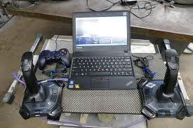
4 Laptop / Joysticks / Controller Driver Station on laptop 4


5 Radio on Robot Allows you to control the robot wirelessly Wireless communication between the robot (roborio and Laptop Radio is configured by special computers at competition POE goes in this port (orange split cable) Ethernet connections for power over ethernet and roborio connection 5
 Always be aware of polarity when connecting any electrical component on the robot")
6 Battery Is the only source of power on the robot Provides 12 Volts DC to the Power Distribution Panel (PDP) Red/Black connections on PDP used to distribute power from battery to all electrical components on the robot Red wire connects to + Black wire connects to - (ground or common) Always be aware of polarity when connecting any electrical component on the robot 6

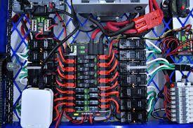
7 Power Distribution Panel (PDP) Provides power from battery to ALL electronics Red/Black connections provide 12V DC from battery to robot electronic equipment connects to battery Slots for fuses 7

8 RoboRIO Computer on the robot Java code for the robot is deployed onto the roborio Controls motor controllers, relays, most sensors, the robot signal light, and custom electronics CAN is used for TalonSRX motor controllers connects to radio Digital I/O connects to limit switches, sensors, and custom electronics for most motor controllers 8

9 Voltage Regulator Module (VRM) Provides power (from the PDP) to components that require regulated power Regulated power will NOT decrease in voltage when the battery is low, or if there is a large load. This is used for things that need constant power camera power in from PDP ex: radio, camera radio 9


10 Motors Only certain motors are allowed by the competition manual Motors get DC power from motor controllers battery power ----> PDP ----> motor controllers ---->motor 10
11 Motor Controllers Motor controllers (MCs) are wired between the PDP and the motor Provide power to motors - but with intelligence also (PWM signal) MCs use a PWM control signal to determine how much of the 12-Volt battery voltage to provide to the motor at any moment: no voltage partial voltage forward partial voltage reverse full voltage forward full voltage reverse PWM control signal is carried to motor controller on a PWM cable PWM signal comes from the roborio (except Talon SRX motor controller has onboard computing power and uses the CAN bus for control signals) Control Signals originate from: Operator Interfaces (joysticks, controller connected to the laptop) Onboard Sensors (limit switches, encoders, optical sensors) Robot code (Java code deployed on the roborio) 11
 PWM cable provides control signal (from roborio PWM port) VV+ Indicator LED : Orange: No signal (neutral signal) Flashing")

12 Victor (old model Motor Controller) Used to control a motor Gets input voltage from PDP (V+/V-) leads Output voltage is applied to Motor (M+/M- leads) PWM cable provides control signal (from roborio PWM port) VV+ Indicator LED : Orange: No signal (neutral signal) Flashing Orange: Stop Signal Green - Full Forward Red - Full Reverse No LIght - forward/reverse 1-99% In BRAKE mode a Motor Controller will short together the motor +/- to make the motor stop faster. In COAST mode the applied voltage will go to zero to allow the motor to coast to a stop. 12

13 Victor SP (newer model Motor Controller) Used to control motors LEDs indicate status POWER (from PDP) * Solid orange - PWM signal is neutral Blink orange - no PMW signal Blink red -Reverse PWM signal, blinks proportional to input Solid red - Full Reverse PWM signal applied Blink green - Forward PWM signal, blinks proportional to input Solid green - Full Forward PWM signal applied Red/Orange - damaged hardware Brake/Coast Cal Button: Red = Brake Off = Coast *Also has PWM cable for control signal (not shown in this photo) Connection to motor 13

14 Talon SRX (newer Motor Controller with onboard computing and CAN bus) Power (from PDP) used for direct connection to encoder used to control motors uses a CAN bus to connect to each other and the roborio Talon SRXs are connected to each other via the CAN bus, and only one is connected to the roborio, rather than each controller having a PWM directly to the roborio has onboard computing power which frees up the roborio and speeds up the processing special capabilities built in for easier programming to control robot s motion in autonomous CAN connection LED indicator Connections to motor 14

15 Servo A servo is a small, low power motor that can only rotate 180 degrees. There is no way to control the speed of a servo, instead you tell the servo which angle to be at. You cannot do this with a normal motor without some sensors and a lot of programming. A servo connects directly to a PWM port on the roborio. It does NOT use a motor controller. It requires that the 6V jumper next to the PWM port is in place on the roborio. 15
.")
16 Spike Relay Controls motor, but only full forward, full reverse, or off Connects power from PDP directly to load (such as a motor) Uses yellow 20 Amp non-resetting fuse. This fuse will not reset if blown and will need to be replaced. Connection to power distribution panel Connection to load (such as a motor, light, compressor, etc). Connection to Relay ports on roborio (commands relay to pass power forward or reverse, or not to pass any power) Indicator Light: Orange-Off Red-Reverse Green-Forward 16
 NC-Normally closed lets current flow until switch is pressed.")
17 ONBOARD SENSORS Limit Switches Has COM, NO and NC connections COM connects to DIO Signal port on RoboRio NO connects to GND NC connects to POWER NO-normally open no current flows until switch is pressed. Is normally an open circuit (non-connected) NC-Normally closed lets current flow until switch is pressed. Is normally a closed circuit (connected) 17

18 ONBOARD SENSORS Digital Encoders Measure RPM, direction, and angle of rotating shaft Many counts per each revolution, so can be used for very accurate determination of number of revolutions or partial revolutions Attached to robot drive shaft, can be used to measure distance wheel has traveled very accurately for autonomous motion Has A and B channels that each connect to a different digital input on the roborio DIO ports 18
 Series 63R, Series")
19 EN - Rotary Optical Encoder ENS1J-B28-L00128L (128 cycles per revolution) Series 63R, Series 61K 19
 Only one count per revolution Banner brand QS18VN6D (D=shorter range, 18 ) (LV=longer range, 21 )")

20 ONBOARD SENSORS Optical Sensor (Counter) Can count number of revolutions on spinning objects like a wheel (using a light beam) Only one count per revolution Banner brand QS18VN6D (D=shorter range, 18 ) (LV=longer range, 21 ) brown wire connects to red on VRM (12V) or PDB blue wire connects to black on PDB white wire connects to DIO signal port on roborio black wire is not connected Count = number of counts per second. Convert to RPM for setspeed command 20

21 ONBOARD SENSORS navx Gyro measures angles used mostly for turning in auto mounts directly onto roborio 21

 when the")

22 Camera Connects to roborio by USB Driver can see the camera s view from the SmartDashboard (on the computer) when the robot is connected Can be used as a sensor for vision processing 22
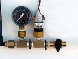
23 Pneumatics (air) The robot pneumatic system uses the power of compressed air to push a piston on a pneumatic cylinder Air compressor fills air tanks with high pressure air (120 psi) Regulator provides lower pressure air (60 psi) to solenoid valves Robot code commands solenoid valves open/closed to move pneumatic pistons All parts are connected using pneumatic tubing Solenoid valves and compressor are powered from the Pneumatics Control Board (PCB) PCB gets regulated power from the power distribution panel (PDP) 23
24 Pneumatics Secondary Regulator (anything<60) Compressor Primary regulator (60 psi) Air Storage Tanks (120 psi) Solenoid valve Solenoid valve Solenoid valve Cylinder Cylinder Cylinder 24

25 Pneumatic Control Module (PCM) used to control pneumatics (air) provides power to compressor and up to 8 solenoid valves receives power from special regulated power connections on bottom of PDP 25
26 Pneumatics cont d 26


27 Double Solenoid Valve Connects to the solenoid channels on the PCM Can only be switched to A or B Will remain in the position it was in last when power is removed Controls pneumatic cylinder 1 2 Output 1 Output 2 Input 3 Switched to A Lets air from input through Lets air come out Lets air through to and leave the valve 1 Switched to B Lets air come out and leave the vale Lets air come Lets air through to through from input

28 Others Robot signal light (RSL) Main Breaker *** This is how you turn the robot on and off 28

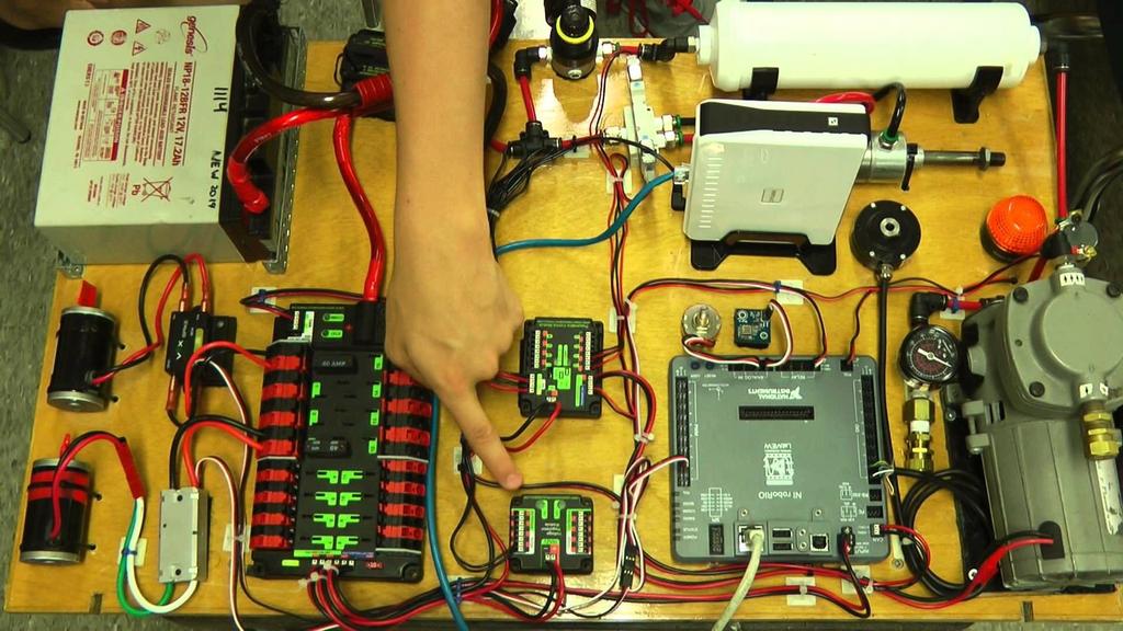
29 All of it 29
 means a thicker wire Battery to power distribution board uses 6")
30 Must follow chart provided in Season Manual for required wire sizes Lower gauge (AWG) means a thicker wire Battery to power distribution board uses 6 AWG 30


31 Used for PWM, Relay, and sensor connections Made up of connector housing and either male or female inserts The three leads are spaced at 0.1 apart Wires are crimped into male/female inserts which are inserted into housing. Can make your own so that the cable is exactly the right length Female Finished Connector Male Wire with female connectors 31

 Yellow fork-connects to screws on victor/jaguar")
32 Some are have little covers We mainly use the quick disconnect type Yellow is for thick wires, blue is for medium thick wires, and red is for really thin wires. Color only affects the part where the wire goes in, and not the size of the connector that is sticking out. From left to right: Yellow/blue butt connectors-joins two wires (not good) Yellow fork-connects to screws on victor/jaguar Red ring-connects to screws on victor We have all three types The top row has built in heat shrink 32


33 thin Crimp connectors Same yellow blue red Also, there are two thicknesses of the male/female ends We mainly use the thicker ones Some are covered and others are not Can connect to each other to make longer wires Can connect to the tabs on the end of the spike Can connect to tabs that we put on the Victors thick Anderson connector used for batteries 33
34 Useful Resources Getting Started with the 2018 FRC Control System /Status_Light_Quick_Reference.pdf? (Provides info on what indicator lights mean for many FRC electronic components) (FRC Pnuematics Manual) FRC Electrical Bible (work in progress by Team 2853) 34
35 Programming Driver Station RoboRIO Web Dashboard 35
")
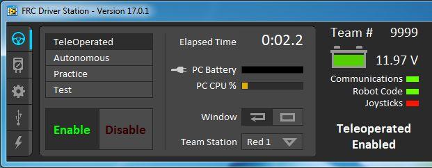
36 Driver Station Sends all commands to control the robot Operation Tab robot mode enable/disable the robot from running Elapsed time displays the amount of time since the robot was enabled error messages/ print statements robot status (comms, battery life, etc) 36

37 Diagnostics Tab lights turn green when the item is connected 37
 to mimic FMS data sent to your robot at the start of the match The")
38 Setup Tab The team number allows the driver station to communicate with the roborio that is configured for that team It will also set up your network for that number select SmartDashboard here to open the SmartDashboard for Power Up you can input field configurations (which side of the scale/switches are your alliance s color) to mimic FMS data sent to your robot at the start of the match The practice round timings can be changed, and match sound effects can be enabled 38


39 Charts Tab Spikes in the green and blue lines indicate network problems Yellow indicates battery voltage Red indicates crio CPU usage If it is 100% then the program has a problem and the robot will not be controllable 39
40 RoboRIO Web Dashboard roborio-236-frc.local allows you to view various info about the roborio and other components when the robot is connected see info about roborio and update its firmware TalonSRX s - change ID s, update firmware, tune motion control 40
Status Light Quick Reference
 Status Light Quick Reference Many of the components of the FRC Control System have indicator lights that can be used to quickly diagnose problems with your robot. This guide shows each of the hardware
Figure 1. DMC 60 components.
 1300 Henley Court Pullman, WA 99163 509.334.6306 www.digilentinc.com DMC 60 Reference Manual Revised November 15, 2016 This manual applies to the DMC 60 rev. A Overview The DMC 60 is an electronic speed
Welcome to Electrical Design and Wiring for Indiana F.I.R.S.T Teams
 Welcome to Electrical Design and Wiring for Indiana F.I.R.S.T Teams Presenters Chris Noble - Team 829 Mentor Cornerstone Controls Engineer Darrell Noble - Team 71 Mentor Bemcor Engineer Combined 28 years
12V Victor 888 User Manual
 The Victor speed controllers are specifically engineered for robotic applications. The high current capacity, low voltage drop, and peak surge capacity make the Victor ideal for drive systems while its
Blue Point Engineering
 Blue Point Engineering Instruction I www.bpesolutions.com Pointing the Way to Solutions! Puppet - II+ Controller (BPE No. PCA-0001) Servo Position Adjustment EEPROM Digital Button Power 5 Vdc Playback
100A PWM Input Pulse (High Time) 1 2 ms Nominal ms max PWM Input Rate (Period) ms PWM Output Chop Rate (Switching Frequency)
 1 2 ms Nominal ms max PWM Input Rate (Period) ms PWM Output Chop Rate (Switching Frequency)") The Victor SP is a speed controller designed through collaboration between VEX Robotics (VEX.com) & Cross the Road Electronics () that allows for fine control and high performance of brushed DC motors
The Victor SP is a speed controller designed through collaboration between VEX Robotics (VEX.com) & Cross the Road Electronics () that allows for fine control and high performance of brushed DC motors
Blue Point Engineering
 Blue Point Engineering Instruction I www.bpesolutions.com Pointing the Way to Solutions! Animatronic Wizard - 3 Board (BPE No. WAC-0030) Version 3.0 2009 Controller Page 1 The Wizard 3 Board will record
Brushed DC Motor Control. Module with CAN (MDL-BDC24)
") Stellaris Brushed DC Motor Control Module with CAN (MDL-BDC24) Ordering Information Product No. MDL-BDC24 RDK-BDC24 Description Stellaris Brushed DC Motor Control Module with CAN (MDL-BDC24) for Single-Unit
Stellaris Brushed DC Motor Control Module with CAN (MDL-BDC24) Ordering Information Product No. MDL-BDC24 RDK-BDC24 Description Stellaris Brushed DC Motor Control Module with CAN (MDL-BDC24) for Single-Unit
Jaguar Motor Controller (Stellaris Brushed DC Motor Control Module with CAN)
") Jaguar Motor Controller (Stellaris Brushed DC Motor Control Module with CAN) 217-3367 Ordering Information Product Number Description 217-3367 Stellaris Brushed DC Motor Control Module with CAN (217-3367)
Jaguar Motor Controller (Stellaris Brushed DC Motor Control Module with CAN) 217-3367 Ordering Information Product Number Description 217-3367 Stellaris Brushed DC Motor Control Module with CAN (217-3367)
BrewsBySmith.com STC DIY Kit
 BrewsBySmith.com STC-1000 + DIY Kit Contact Information: Greg Smith www.brewsbysmith.com greg@boostbysmith.com I. Hardware Included: STC-1000 flashed with latest software (v1.06 currently) (if purchased)
Citrus Circuits Fall Workshop Series. Roborio and Sensors. Paul Ngo and Ellie Hass
 Citrus Circuits Fall Workshop Series Roborio and Sensors Paul Ngo and Ellie Hass Introduction to Sensors Sensor: a device that detects or measures a physical property and records, indicates, or otherwise
Tarocco Closed Loop Motor Controller
 Contents Safety Information... 3 Overview... 4 Features... 4 SoC for Closed Loop Control... 4 Gate Driver... 5 MOSFETs in H Bridge Configuration... 5 Device Characteristics... 6 Installation... 7 Motor
Electronic regulator for PWM controlled proportional solenoid valves FABER -
 Electronic regulator for PWM controlled proportional solenoid valves STU Control Unit FABER - COM DESCRIPTION STU-PWM electronic card is a regulator for proportional solenoid valves, which can drive up
Mach3 USB Motion Card (STB5100) Installation Manual
 Installation Manual") Mach3 USB Motion Card (STB5100) Installation Manual V2.1 The motion control card for machine control, with strong professional. Requires the operator to have the relevant expertise! If used improperly,
Mach3 USB Motion Card (STB5100) Installation Manual V2.1 The motion control card for machine control, with strong professional. Requires the operator to have the relevant expertise! If used improperly,
WIRING SCHEMATICS FOR SOFTWARE VERSIONS 5.13 AND HIGHER
 55 S. Vineyard Avenue Ontario, CA 976 (909) 93-973 WIRING SCHEMATICS FOR SOFTWARE VERSIONS 5.3 AND HIGHER FOR CURTIS 39 CONTROLLER ON-ROAD VEHICLE CONVERSION FOR SINGLE AND WITH DUAL MOTOR APPLICATIONS
Digital Multifunctional RC-Soundmodule TBS Mini V2
 Digital Multifunctional RC-Soundmodule TBS Mini V2 Important notes about changes on the NEW TBS Mini V2!!! MUST BE READ!!! New connector: External amplifier Volume Unchanged connectors (same as old TBS
Blue Point Engineering
 lue Point Engineering Wizard - I Interface oard http://www.pesolutions.com (303) 651.3794 Pointing the Way to Solutions! Talking / Eye Moving Skull Connectors pplication Examples 7805 Eyeball Jar nimatronic
VEX Robotics Platform and ROBOTC Software. Introduction
 VEX Robotics Platform and ROBOTC Software Introduction VEX Robotics Platform: Testbed for Learning Programming VEX Structure Subsystem VEX Structure Subsystem forms the base of every robot Contains square
Getting Started Guide
 Stellaris MDL-BDC24 Brushed DC Motor Control Module Getting Started Guide MDL-BDC24-GSG-04 Copyright 2009 2011 Texas Instruments Copyright Copyright 2009 2011 Texas Instruments, Inc. All rights reserved.
Blue Point Engineering
 DMX -Channel Relay Board Overview A two-channel DMX relay switch for switching loads up to 0A at 40V AC per channel. he DMX switch operates on the standard DMX5 bus and requires - DMX channels for operation.
Built-in soft-start feature. Up-Slope and Down-Slope. Power-Up safe start feature. Motor will only start if pulse of 1.5ms is detected.
 Thank You for purchasing our TRI-Mode programmable DC Motor Controller. Our DC Motor Controller is the most flexible controller you will find. It is user-programmable and covers most applications. This
Scorpion HX User Manual R/C Version
 Table of Contents Features...3 Connections...5 Setup...5 Setup Complete...10 Status Codes...11 Mounting your Scorpion...12 Notes on PCM radios...12 Service and Support...13 Limitations and Warrantees...13
ScaleRCHelis.com Light Controller Users Manual
 This manual is for both the 450 and High Power light controllers. The difference between the two controllers: The 450 controller is only single input allowing the user to directly control the landing and
Jaguar speed controllers
 Jaguar speed controllers When used with CAN control, Jaguars are smart speed controllers. You can simply send a command to the Jaguar such as a position setpoint and it will use attached sensors to move
Gael Force FRC Team 126
 Gael Force FRC Team 126 2018 FIRST Robotics Competition 2018 Robot Information and Specs Judges Information Packet Gael Force is proof that one team from a small town can have an incredible impact on many
Introduction to the VEX Robotics Platform and ROBOTC Software
 Introduction to the VEX Robotics Platform and ROBOTC Software Computer Integrated Manufacturing 2013 Project Lead The Way, Inc. VEX Robotics Platform: Testbed for Learning Programming VEX Structure Subsystem
Exercise 10. Linear Slides EXERCISE OBJECTIVE
 Exercise 10 Linear Slides EXERCISE OBJECTIVE In this exercise, you will learn to use a linear slide. You will learn how to use the Linear Slide, Model 5209, to extend the work envelope of the Servo Robot.
Endurance R/C Wi-Fi Servo Controller 2 Instructions
 Endurance R/C Wi-Fi Servo Controller 2 Instructions The Endurance R/C Wi-Fi Servo Controller 2 allows you to control up to eight hobby servos, R/C relays, light controllers and more, across the internet
Coils & Electronic Controls
 HYDRAFORCE Coils & Electronic Controls COILS FOR SOLENOID OPERATED VALVES Standard Coils and Proportional Valve Coils... 3.200.1 Series E Water/Weather Resistant Coils... 3.400.1 ELECTRONIC CONTROLS FOR
MD04-24Volt 20Amp H Bridge Motor Drive
 MD04-24Volt 20Amp H Bridge Motor Drive Overview The MD04 is a medium power motor driver, designed to supply power beyond that of any of the low power single chip H-Bridges that exist. Main features are
CNC Router Parts CNC Router Parts 2.2 kw Plug and Play Spindle / VFD System CRP800 Set Up Guide
 Step 1: Congratulations on your purchase of the 2.2 kw Plug and Play Spindle / VFD System! The first step in setting up your Spindle will be to physically connect your VFD to your CRP800 Control Unit with
All Girls Tournament 2017
 All Girls Tournament 2017 Agenda Student team roles Pits and preparing your robot for competition Troubleshooting your robot Behind the Glass Field Volunteers Q and A Preparing robot for each match in
Introduction to the EXPANSION HUB
 Introduction to the EXPANSION HUB REV ROBOTICS - EXPANSION HUB revrobotics.com ANOTHER CONTROLLER CHOICE MODERN ROBOTICS REV ROBOTICS The Expansion hub does not replace the Modern Robotics System. It is
Workshops Elisava Introduction to programming and electronics (Scratch & Arduino)
") Workshops Elisava 2011 Introduction to programming and electronics (Scratch & Arduino) What is programming? Make an algorithm to do something in a specific language programming. Algorithm: a procedure
Workshops Elisava 2011 Introduction to programming and electronics (Scratch & Arduino) What is programming? Make an algorithm to do something in a specific language programming. Algorithm: a procedure
Experiment #3: Micro-controlled Movement
 Experiment #3: Micro-controlled Movement So we re already on Experiment #3 and all we ve done is blinked a few LED s on and off. Hang in there, something is about to move! As you know, an LED is an output
Mechatronics Engineering and Automation Faculty of Engineering, Ain Shams University MCT-151, Spring 2015 Lab-4: Electric Actuators
 Mechatronics Engineering and Automation Faculty of Engineering, Ain Shams University MCT-151, Spring 2015 Lab-4: Electric Actuators Ahmed Okasha, Assistant Lecturer okasha1st@gmail.com Objective Have a
Running the PR2. Chapter Getting set up Out of the box Batteries and power
 Chapter 5 Running the PR2 Running the PR2 requires a basic understanding of ROS (http://www.ros.org), the BSD-licensed Robot Operating System. A ROS system consists of multiple processes running on multiple
SpeedTube Operations Manual
 SpeedTube Operations Manual 955424_01 2/16 1 Contents SpeedTube Setup... 3 Swath Calibration... 5 SpeedTube Operation... 6 Vacuum Setting... 6 Good Ride Metric... 7 SpeedTube Diagnostics... 7 SpeedTube
Maintenance Information
 47104302 Edition 1 November 2012 Cordless Drill/Driver QX Series Maintenance Information Save These Instructions Tool Diagnosis 1. Before servicing this unit, you will need a fully charged battery of known
Logosol AC/DC Programmable Servo & Logic Controller LS-151
 Features Motors supported - Panasonic A and S series motors - Yaskawa SGM and SGMM series - Brushless 60/120º commutated (AC) - Brush-commutated (DC) 12A peak, 8A continuous output current 18 to 91V motor
The Datasheet and Interfacing EE3376
 The Datasheet and Interfacing EE3376 MSP430 Datasheet Modes of the MSP430 Active Mode (this class) LPM0 (CPU asleep) LPM3 (only ACLK on) LPM4 (sleep mode) 0 0 0 0 250uA 0 0 0 1 35 ua 1 1 0 1 1 ua 1 1 1
Appendix E VEX U. VEX Robotics Competition Turning Point Appendix E
 Appendix E VEX U Introduction We are thrilled to continue the exciting VEX U program for another year, with some new twists for the 2018-2019 season. While many colleges and universities already use the
B Robo Claw 2 Channel 25A Motor Controller Data Sheet
 B0098 - Robo Claw 2 Channel 25A Motor Controller Feature Overview: 2 Channel at 25A, Peak 30A Hobby RC Radio Compatible Serial Mode TTL Input Analog Mode 2 Channel Quadrature Decoding Thermal Protection
MTY (81)
") This manual describes the option "e" of the SMT-BD1 amplifier: Master/slave tension control application. The general information about the digital amplifier commissioning are described in the standard
This manual describes the option "e" of the SMT-BD1 amplifier: Master/slave tension control application. The general information about the digital amplifier commissioning are described in the standard
Directions for Wiring and Using The GEARS II (2) Channel Combination Controllers
 Channel Combination Controllers") Directions for Wiring and Using The GEARS II (2) Channel Combination Controllers PWM Input Signal Cable for the Valve Controller Plugs into the RC Receiver or Microprocessor Signal line. White = PWM Input
Directions for Wiring and Using The GEARS II (2) Channel Combination Controllers PWM Input Signal Cable for the Valve Controller Plugs into the RC Receiver or Microprocessor Signal line. White = PWM Input
PS2-SMC-06 Servo Motor Controller Interface
 PS2-SMC-06 Servo Motor Controller Interface PS2-SMC-06 Full Board Version PS2 (Playstation 2 Controller/ Dual Shock 2) Servo Motor Controller handles 6 servos. Connect 1 to 6 Servos to Servo Ports and
Quantizer step: volts Input Voltage [V]
![Quantizer step: volts Input Voltage [V]](/thumbs/96/126541381.jpg "Quantizer step: volts Input Voltage [V]") EE 101 Fall 2008 Date: Lab Section # Lab #8 Name: A/D Converter and ECEbot Power Abstract Partner: Autonomous robots need to have a means to sense the world around them. For example, the bumper switches
EE 101 Fall 2008 Date: Lab Section # Lab #8 Name: A/D Converter and ECEbot Power Abstract Partner: Autonomous robots need to have a means to sense the world around them. For example, the bumper switches
* * APPLICABLE MODELS: 2014 > MAZDA 3
 PART NUMBER: 0000 8C L46 GENUINE ACCESSORIES INSTALLATION INSTRUCTIONS Rev. AAA *550-0604-000* APPLICABLE MODELS: 204 > MAZDA 3 REQUIRED COMPONENTS: ITEM QTY DESCRIPTION Usage Chart MIRROR ASSEMBLY: Mirror
FLUSH CONTROL Installation, Operation and Maintenance Instructions Part# STCBL
 WARNING: WARNING: CONTROL Installation, Operation and Maintenance Instructions Part# THE FOLLOWING ARE CAUTIONARY STATEMENTS THAT MUST BE READ AND FOLLOWED DURING BOTH INSTALLATION AND OPERATION. Raritan
Appendix E VEX U. VEX Robotics Competition Turning Point Appendix E
 Appendix E VEX U Introduction We are thrilled to continue the exciting VEX U program for another year, with some new twists for the 2018-2019 season. While many colleges and universities already use the
HT101V Reference Manual
 HT101V Reference Manual Overview The HT101V from Ag-Tester is our handheld tester designed to diagnose valve components on agricultural machinery. Valves tested include: 1- Boom Control Valves 2- Servo
Hardware Guide. Control Made Simple. Model 401A Signal Generator
 Control Made Simple Model 401A Signal Generator Hardware Guide ON OFF LIMIT 1 2 3 4 RXD TXD POWER West Coast Office 1263 El Camino Real Menlo Park, CA 94025 Phone (650) 853-1444 Fax (650) 853-1405 www.flashcutcnc.com
ERROR MESSAGES: Click on Error for further detail PROBE ERROR: PROBE IS OPEN OR NOT CONNECTED.
 ERR MESSAGES: Click on Error for further detail MOT OVERCURRENT:THE PLATEN HAS BEEN MECHANICALLY RESISTED. MOT ERR: NO ENCODER MESSAGE TO THE MOT SPEED CONTROL IGNITION ERR: after the 4 th failed attempt
B RoboClaw 2 Channel 30A Motor Controller Data Sheet
 B0098 - RoboClaw 2 Channel 30A Motor Controller (c) 2010 BasicMicro. All Rights Reserved. Feature Overview: 2 Channel at 30Amp, Peak 60Amp Battery Elimination Circuit (BEC) Switching Mode BEC Hobby RC
VEX IQ Troubleshooting Flowchart Controller & Controller Battery
 Controller & Controller Battery Controller Power/Link Charge/Game Does the Controller turn on When on, the Power/Link LED will be green or red. Unscrew the battery door of the Controller and ensure both
Electronically Commutated (EC) Motor Control with Solo, Select and Sync PWM Boards
 Motor Control with Solo, Select and Sync PWM Boards") Electronically Commutated (EC) Motor Control with Solo, Select and Sync PWM Boards The Solo, Select and Sync PWM boards provide a pulse-width modulated (PWM) signal to the EC motor to control fan speed.
Electronically Commutated (EC) Motor Control with Solo, Select and Sync PWM Boards The Solo, Select and Sync PWM boards provide a pulse-width modulated (PWM) signal to the EC motor to control fan speed.
HAPPY HCS Voyager: Level-1 Maintenance & Repair Intermediate-level repair / maintenance procedures
 TEXMAC Inc. HAPPY HCS Voyager Introduction Training page 1 HAPPY HCS Voyager: Level-1 Maintenance & Repair Intermediate-level repair / maintenance procedures Table of Contents Oiling/Cleaning Page 2 Removing
HB-25 Motor Controller (#29144)
") Web Site: www.parallax.com Forums: forums.parallax.com Sales: sales@parallax.com Technical: support@parallax.com Office: (916) 624-8333 Fax: (916) 624-8003 Sales: (888) 512-1024 Tech Support: (888) 997-8267
Web Site: www.parallax.com Forums: forums.parallax.com Sales: sales@parallax.com Technical: support@parallax.com Office: (916) 624-8333 Fax: (916) 624-8003 Sales: (888) 512-1024 Tech Support: (888) 997-8267
The Allen-Bradley Servo Interface Module (Cat. No SF1) when used with the Micro Controller (Cat. No UC1) can control single axis
 when used with the Micro Controller (Cat. No UC1) can control single axis") Table of Contents The Allen-Bradley Servo Interface Module (Cat. No. 1771-SF1) when used with the Micro Controller (Cat. No. 1771-UC1) can control single axis positioning systems such as found in machine
Table of Contents The Allen-Bradley Servo Interface Module (Cat. No. 1771-SF1) when used with the Micro Controller (Cat. No. 1771-UC1) can control single axis positioning systems such as found in machine
DeviceCraft Revision #1 11/29/2010
 DeviceCraft Revision #1 11/29/2010 DC Wiper Motor H-Bridge Servo / Speed Controller P/N 1020 Features: Dip Switch selectable mode of operation Both PID servo or speed controller Forward/Reverse operation
Micro Wizard Instructions
 How to install FAST TRACK K3 4-digit actual times and 1-digit sequence of finish display timer with Computer Serial Interface Enclosed you will find the Fast Track finish line, AC adapter and remote start
MegaPoints Controller
 MegaPoints Controller A flexible solution and modular component for controlling model railway points and semaphore signals using inexpensive servos. User guide Revision 10c March 2015 MegaPoints Controllers
3DR ArduCopter Quad-C
 3DR ArduCopter Quad-C 3DR ArduCopter Quad-C Thank you for purchasing a 3DR ArduCopter Quad kit. The 3DR ArduCopter Quad is a stable and supported multi-rotor frame in the ongoing development of the ArduCopter
Hydraulic Clamp Carrier. Installation & Operation Manual
 Hydraulic Clamp Carrier Installation & Operation Manual Hydraulic Clamp Carrier Installation & Operation Manual Quick Machinery Company 8272 Peninsula Drive Kelseyville, CA 95451 phone: (707) 272-6719
GENUINE ACCESSORIES INSTALLATION INSTRUCTIONS. ITEM QTY DESCRIPTION Usage Chart
 PART NUMBER: 0000 8C R0 GENUINE ACCESSORIES INSTALLATION INSTRUCTIONS Rev. AAA *550-0554-000* APPLICABLE MODELS: 203 > CX-5 REQUIRED COMPONENTS: ITEM QTY DESCRIPTION Usage Chart MIRROR ASSEMBLY: Mirror
DMX Digital-Servo Board
 Version 1.0 2012 WD197 Overview he DMX DigitalServo module is designed to provide 8 consecutive channels of output from a standard DMX protocol input signal. he outputs may be configured to be 5VDC digital
30AUTO Speed Lathe Manual
 30AUTO Speed Lathe Manual Standard Features 3/4 HP Motor Air-Collet Closure 1800 RPM, Single Speed Electric Brake Cast Housing 5C Collets 3 Phase / 240 Volts DESCRIPTION: The Crozier Model 30AUTO Automotive
Assembly Manual for VFO Board 2 August 2018
 Assembly Manual for VFO Board 2 August 2018 Parts list (Preliminary) Arduino 1 Arduino Pre-programmed 1 Faceplate Assorted Header Pins Full Board Rev A 10 104 capacitors 1 Rotary encode with switch 1 5-volt
Blue Point Engineering
 Overview Blue Point Instruction Board 2-CH Boards, Terminal Block and Ribbon Cable I Type: RF Radio (315 MHz) 1-2 Channels (FCC Part 15 Compliant Components). Operating Voltage: 6-15 VDC @ 1 Amp (Wall
USB-MC USB Motion Controller
 USB-MC USB Motion Controller Con2 I/O port, to I/O card Con4 Aux port, inputs and outputs Con3 parallel port, to I/O card Con1 USB port to PC Con5 external power supply 8 24 VDC Status LED - + Comm. LED
General Description. The TETRIX MAX Servo Motor Expansion Controller features the following:
 General Description The TETRIX MAX Servo Motor Expansion Controller is a servo motor expansion peripheral designed to allow the addition of multiple servo motors to the PRIZM Robotics Controller. The device
MegaPoints Servo Controller
 MegaPoints Servo Controller Covers Servo Controller boards 1.8 onwards A flexible and modular device for controlling model railway points and semaphore signals using inexpensive R/C servos and relays.
Ultimate Actuator Drivebox 30A Quick start guide
 2016 Ultimate Actuator Drivebox 30A Quick start guide info@e-tronix.cz e-tronix s.r.o. 1.1.2016 OBSAH Identification... 3 Serial Number... 3 Manufacturer and reseller contact... 4 Before Start... 4 UAD30A
Studuino Icon Programming Environment Guide
 Studuino Icon Programming Environment Guide Ver 0.9.6 4/17/2014 This manual introduces the Studuino Software environment. As the Studuino programming environment develops, these instructions may be edited
Analog Servo Drive. Peak Current 16 A (11.3 A RMS )
") Description The PWM servo drive is designed to drive three phase brushless motors with sine wave current at a high switching frequency. The drive requires two sinusoidal command signals with a 120-degree
Description The PWM servo drive is designed to drive three phase brushless motors with sine wave current at a high switching frequency. The drive requires two sinusoidal command signals with a 120-degree
Height Limited Switch
 Height Limited Switch Manual version: 1.0 Content Introduction...3 How it works...3 Key features...3 Hardware...4 Motor cut-off settings...4 Specification...4 Using the RC HLS #1 module...5 Powering the
National Instruments Direct Injector Driver System NI DIDS-2003 NI DIDS-2006 NI DIDS-2009 NI DIDS-2012
 National Instruments Direct Injector Driver System NI DIDS-2003 NI DIDS-2006 NI DIDS-2009 NI DIDS-2012 NI Direct Injector Driver System User Guide May 2014 Table of Contents National Instruments Direct
YGE ProgCard II - Programming Card
 YGE ProgCard II - Programming Card With the programming card, we offer an easy to use programming unit, with which all our ProgCard II capable speed controllers can have their individual functions changed.
Peak Current. Continuous Current. See Part Numbering Information on last page of datasheet for additional ordering options.
 Description Power Range The PWM servo drive is designed to drive brushless DC motors at a high switching frequency. A single red/green LED indicates operating status. The drive is fully protected against
Voltage Regulator Module User s Guide
 Voltage Regulator Module User s Guide Rev 1.1 Cross The Road Electronics www.crosstheroadelectronics.com Cross The Road Electronics Page 1 1/17/016 Table of Contents 1. Voltage Regulation Module at a Glance...
TECHNICAL DATASHEET #TDAX A DC MOTOR CONTROLLER P/N: AX Variable Speed Control, Onboard I/O CAN SAE J1939, Rugged Packaging
 TECHNICAL DATASHEET #TDAX102000 35A DC MOTOR CONTROLLER P/N: AX102000 Variable Speed Control, Onboard I/O CAN SAE J1939, Rugged Packaging with Electronic Assistant Features: Unidirectional or bi-directional
User guide. Revision 1 January MegaPoints Controllers
 MegaPoints Servo 4R Controller A flexible and modular device for controlling model railway points and semaphore signals using inexpensive R/C servos and relays. User guide Revision 1 January 2018 MegaPoints
CANifier User s Guide
 CANifier User s Guide Revision 1.0 Cross The Road Electronics www.ctr-electronics.com Cross The Road Electronics Page 1 10/8/2017 Table of Contents 1. What is CANifier?... 4 1.1. Features... 5 1.2. Pin
HAW-Arduino. Sensors and Arduino F. Schubert HAW - Arduino 1
 HAW-Arduino Sensors and Arduino 14.10.2010 F. Schubert HAW - Arduino 1 Content of the USB-Stick PDF-File of this script Arduino-software Source-codes Helpful links 14.10.2010 HAW - Arduino 2 Report for
MTC-2 highlight features: ACU highlight features: Contents. MTC-2 and ACU User Manual V4.0
 MTC-2 can work alone as a twin motor ECS (electronic speed controller) for RC tanks. When the ACU (auxiliary control unit) is connected, it can also control turret rotation, gun elevation, gun firing,
Proximity-Sensor Counter Installation Instruction Model: MRC-PRO
 Proximity-Sensor Counter Installation Instruction Model: MRC-PRO NYS DOT Approval SYSDYNE CORP. 1055 Summer St. 1 st Floor Stamford, CT 06905 Tel: (203)327-3649 Fax: (203)325-3600 Contents: Introduction...
Arducopter 3DR-B Hardware
 Arducopter 3DR-B Thank you for purchasing an Arducopter 3DR kit. The Arducopter 3DR is a stable and supported quadrotor frame in the ongoing development of the Arducopter code on DIYDrones. It features
Smart Power Relay E I...
 Smart Power Relay E-48-8I... Description The Smart Power Relay E-48-8I.- is a remotely controllable electronic load disconnecting relay with three functions in a single unit: l electronic relay l electronic
Analog Servo Drive 20A20
 Description Power Range NOTE: This product has been replaced by the AxCent family of servo drives. Please visit our website at www.a-m-c.com or contact us for replacement model information and retrofit
USER MANUAL. EPP Intelligent Positioner Control Unit 1/22.
 USER MANUAL - Intelligent Positioner Control Unit 1/22 Table of contents: 1 General... 3 1.1 Safety instructions... 3 2 Application... 4 3 Electrical specifications and terminals... 5 3.1 Control loop...
Sorting Line with Detection 9V
 536628 Sorting Line with Detection 9V I2 O8 I1 I3 C1 I5 I6 I4 Not in the picture: O5, O6, O7, O8 Circuit layout for Sorting Line with Detection Terminal no. Function Input/Output 1 color sensor I1 2 phototransistor
InstaSPIN-BLDC Lab. DRV8312 Setup Jumpers and switches must be setup properly or the kit will not function correctly!
 InstaSPIN-BLDC Lab Introduction For this lab we are using the DRV8312 Low Voltage, Low Current Power Stage (the DRV8301/2 Kit can also be used) with Piccolo F28035 controlcard to run the sensorless InstaSPIN-BLDC
Series 70 Servo NXT - Modulating Controller Installation, Operation and Maintenance Manual
 THE HIGH PERFORMANCE COMPANY Series 70 Hold 1 sec. Hold 1 sec. FOR MORE INFORMATION ON THIS PRODUCT AND OTHER BRAY PRODUCTS PLEASE VISIT OUR WEBSITE www.bray.com Table of Contents 1. Definition of Terms.........................................2
Feedback Devices. By John Mazurkiewicz. Baldor Electric
 Feedback Devices By John Mazurkiewicz Baldor Electric Closed loop systems use feedback signals for stabilization, speed and position information. There are a variety of devices to provide this data, such
Software User Manual
 Software User Manual ElectroCraft CompletePower Plus Universal Servo Drive ElectroCraft Document Number: 198-0000021 2 Marin Way, Suite 3 Stratham, NH 03885-2578 www.electrocraft.com ElectroCraft 2018
Pi Servo Hat Hookup Guide
 Page 1 of 10 Pi Servo Hat Hookup Guide Introduction The SparkFun Pi Servo Hat allows your Raspberry Pi to control up to 16 servo motors via I2C connection. This saves GPIO and lets you use the onboard
RC Camera Control. User Guide v1.3 (RCCC v1.1) 11/7/2012
 11/7/2012") RC Camera Control User Guide v1.3 (RCCC v1.1) 11/7/2012 kristaps_r@rcgroups INTRODUCTION RC Camera Control board (RCCC) is multifunctional control board designed to for aerial photography or First Person
RC Camera Control User Guide v1.3 (RCCC v1.1) 11/7/2012 kristaps_r@rcgroups INTRODUCTION RC Camera Control board (RCCC) is multifunctional control board designed to for aerial photography or First Person
Micro Wizard Instructions
 How to install your Fast Track flashing light display timer model K1 with optional remote start switch (If you have ordered the Quick Mount or have a Best Track, disregard this section and refer to the
Positive Promotion: Use the FIRST and FTC logos in a manner that is positive and promotes FIRST.
 You have incredibly creative opportunities in terms of designing your own identity. There are many examples of how teams brand their efforts with websites, incredible team logos on robots, T shirts, hats,
o What happens if S1 and S2 or S3 and S4 are closed simultaneously? o Perform Motor Control, H-Bridges LAB 2 H-Bridges with SPST Switches
 Cornerstone Electronics Technology and Robotics II H-Bridges and Electronic Motor Control 4 Hour Class Administration: o Prayer o Debriefing Botball competition Four States of a DC Motor with Terminals