Ultra-Compact GaN- or SiC-Based Single-Phase DC/AC Power Conversion
|
|
|
- Allison Morgan
- 5 years ago
- Views:
Transcription

 Zurich")
1 The Little Box Challenge Ultra-Compact GaN- or SiC-Based Single-Phase DC/AC Power Conversion J. W. Kolar, D. Neumayr, D. Bortis Swiss Federal Institute of Technology (ETH) Zurich Power Electronic Systems Laboratory

2 1/135 Outline The Little Box Challenge Little Box 1.0 Concepts & Performances of Other Finalists Analysis of Advanced Concepts Optimization of Little Box 1.0 Little Box 2.0 Little Box 3.0 / Conclusions Acknowledgement 0. Knecht F. Krismer M. Guacci L. Camurca M. Kasper E. Hatipoglu

3 Little Box Challenge Requirements The Grand Prize Finalists & Finals
 Efficiency > 95% Case Temp. < 60 C EMI FCC Part 15 B!!!! Push the Forefront of New Technologies in R&D of High Power Density Inverters")
4 2/135 Design / Build the 2kW 1-ΦSolar Inverter with the Highest Power Density in the World Power Density > 3kW/dm 3 (> 50W/in 3, multiply kw/dm 3 by Factor 16) Efficiency > 95% Case Temp. < 60 C EMI FCC Part 15 B!!!! Push the Forefront of New Technologies in R&D of High Power Density Inverters

5 3/135 The Grand Prize Highest Power Density (> 50W/in 3 ) Highest Level of Innovation $1,000,000 Timeline Challenge Announced in Summer Teams Registered Worldwide 100+ Teams Submitted a Technical Description until July 22, Finalists (3 No-Shows)
6 4/135 Finalists * and FH IZM / Fraza d.o.o. Univ. of Illinois (12) Cambridge CE+T (9) Active Venderbosch (4) Magnetics (15) OKE Services (14) AHED (10) Rompower (7) Tommasi Bailly (8) Virginia Tech (1) Energy Layer (5) Fraunhofer IISB (11) Univ. of Tennessee (3) Schneider Electric (2) (6) * - 5 Companies - 6 Consultants - 4 Universities AMR (13) 15 Teams/Participants in the NREL Note: Numbering of Teams is Arbitrary..


7 5/135 Final Presentations Finalists Invited to NREL / USA Presentations on Oct. 21, 2015 Subsequent Testing by NREL

8 Little Box 1.0 Converter Topology Modulation & Control Technologies /Components Mechanical Concept Exp. Analysis Acknowledgement

9 Derivation of Converter Concept
10 1-Φ Output Power Pulsation Buffer


11 6/135 Power Pulsation Buffer Parallel DC Input Series DC Input Parallel Approach for Limiting Voltage Stress on Converter Stage Semiconductors
")


12 7/135 Passive Power Pulsation Buffer (1) Electrolytic Capacitor S 0 = 2.0 kva cos Φ 0 = 0.7 V C,max = 450 V ΔV C /V C,max =3 % 5 x 493μF/450 V C = 2.46 mf C > 2.2mF / 166 cm 3 Consumes 1/4 of Allowed Total Volume!
 Series")


13 8/135 Passive Power Pulsation Buffer (2) Series Resonant Circuit / Used in Rectifier Input Stage of Locomotives f r = 120Hz * C r = 20 μf * L r = 127 v Lr = 400 V Unacceptably Large Inductor Volume! Electronic Inductor
14 9/135 Partial Active Power Pulsation Buffer Coupling Capacitor & Electronic Inductor Processing Only Partial Power Electronic Inductor * Ertl (1999) * Enslin (1991) * Pilawa (2015) Low U C,aux Low Converter Losses High Values of C K, C aux Required for Low U C,aux Full-Bridge Aux. Converter Allows Lower U C,aux


15 10/135 Partial Active Power Pulsation Buffer Coupling Capacitor & Electronic Inductor Low U C,aux Low Converter Losses High Values of C K, C aux Required for Low U C,aux Full-Bridge Aux. Converter Allows Lower U C,aux Properties of Full-Bridge Aux. Conv.


16 11/135 Full Active Power Pulsation Buffer * Kyritsis (2007) Large Voltage Fluctuation Foil or Ceramic Capacitor Buck- or Boost-Type DC/DC Interface Converter Buck-Type allows Utilizing 600V Technology CeraLink 108 x 1.2 μf /400 V C k 140 μf V Ck = 23.7cm 3 Significantly Lower Overall Volume Compared to Electrolytic Capacitor
17 Output Stage Topology / Modulation
 Analysis Only for cos Φ =")
18 12/135 Derivation of Output Stage Topology (1) Inversion of Basic 1-Φ PFC Rectifier Topology Boost-Type 1-Φ PFC Rectifier DC/ AC Buck Converter & Mains Frequency Unfolder * Erickson (2009) Analysis Only for cos Φ = -1

19 13/135 DC/ AC -Buck Conv. & Unfolder Only Single Bridge Leg for Current Shaping Voltage Zero Crossing For ZVS TCM Operation of Buck-Stage Bridge Leg AC Voltage Cannot be Controlled Down to Zero
20 14/135 Advanced DC/ AC -Buck Conv. & Unfolder Temporary PWM Operation of U < U min to Avoid AC Current Distortion!! CM Component of Output Voltage v O Larger EMI Filtering Requirement Due to Temporary High-Frequ. Switching of Unfolder
 1-Φ Telecom Boost-Type PFC Rectifier Low-Frequency Operation")

21 15/135 Full-Bridge AC/DC Conv. Topology Example of (Bidirectional) 1-Φ Telecom Boost-Type PFC Rectifier Low-Frequency Operation of One Bridge Leg Interleaving for High Part Load Efficiency Si Superjunction MOSFETs h/% V 230V 184V Limit P O /W 72W/in 3 (4.5kW/dm 3 ) incl. Holdup 98.6% Efficiency


22 16/135 Advanced Full-Bridge DC/AC Conv. Topology New Control Concept - PWM Operation of Mains Freq. Bridge u < u 0,min!! CM Component u CM of Generated Output Voltage Potentially Larger EMI Filtering Requirement

23 17/135 Symmetric PWM Full-Bridge AC/DC Conv. Topology Symmetric PWM Operation of Both Bridge Legs No Low-Frequency CM Output Voltage Component DM Component of u 1 and u 2 Defines Output u O CM Component of u 1 and u 2 Represents Degree of Freedom of the Modulation (!)


24 18/135 Remark: AC Side Power Pulsation Buffer Full Bridge Output Stage / Full PWM Operation CM Reactive Power of Output Filter Capacitors used for Comp. of Load Power Pulsation CM Reactive Power prop. 2 C DM Reactive Power prop. ½ C * Serban (2015)

 TCM")


25 19/135 ZVS of Output Stage / TCM Operation * Henze (1988) TCM Operation for Resonant Voltage Turn-On/Turn-Off Requires Only Measurement of Current Zero Crossings, i = 0 Variable Switching Frequency Lowers EMI


26 20/135 CM Enhanced TCM Modulation CM Comp. of u 1, u 2 Changes Sw. Frequency Limits Sw. Frequency Variation Lower Sw. Losses


27 21/135 4D-Interleaving Interleaving of 2 Bridge Legs per Phase - Volume / Filtering / Efficiency Optimum Interleaving in Space & Time Within Output Period Alternate Operation of Bridge Low Power Overlapping High Power Opt. Trade-Off of Conduction & Switching Losses / Opt. Distribution of Losses
28 22/135 Remark: i TCM Inverter Topology TCM : Challenging Inductor Design Superposition of HF & LF Currents itcm: Adding LC-Circuit between Bridge Legs Separation of LF & HF Currents L >>L B TCM itcm * P. Jain (2015) Low Output Current Ripple Reduced Filtering Effort PWM Modulation Applicable Simple Control Strategy Dedicated LF and HF Inductor Designs Possible Improved Converter Efficiency


29 23/135 Selection of Switching Frequency Significant Reduction in EMI Filter Volume for Increasing Sw. Frequency Doubling Sw. Fequ. f S Cuts Filter Volume in Half Upper Limit due to Digital Signal Processing Delays / Inductor & Sw. Losses Heatsink Volume


 Large CM Inductor Needed Filter Volume Mainly")
30 24/135 EMI Filter Topology (1) Conventional Filter Structure DM Filtering Between the Phases CM Filtering Between Phases and PE CM Cap. Limited by Earth Current Limit Typ. 3.5mA for PFC Rectifiers (GLBC: 5mA then 50mA!) Large CM Inductor Needed Filter Volume Mainly Defined by CM Inductors

 No")


31 25/135 EMI Filter Topology (2) Filter Structure with Internal CM Capacitor Feedback Filtering to DC- (and optional to DC+) No Limitation of CM Capacitor C 1 Due to Earth Current Limit µf Instead of nf Can be Employed Allows Downsizing of CM Inductor and/or Total Filter Volume
 Enclosure S ZVS of All Bridge Legs @ Turn-On/Turn-Off in Whole Operating Range (4D-TCM-Interleaving) Heatsinks Connected to DC Bus / Shield to Prevent Cap. Coupling to Grounded Enclosure")
32 26/135 Final Converter Topology Interleaving of 2 Bridge Legs per Phase Active DC-Side Buck-Type Power Pulsation Buffer 2-Stage EMI AC Output Filter (1) Heat Sink (2) EMI Filter (3) Power Pulsation Buffer (4) Enclosure S ZVS of All Bridge Turn-On/Turn-Off in Whole Operating Range (4D-TCM-Interleaving) Heatsinks Connected to DC Bus / Shield to Prevent Cap. Coupling to Grounded Enclosure
33 Technologies Power Semiconductors Cooling DSP/FPGA Auxiliary


34 27/135 Evaluation of Power Semiconductors (1) Accurate Measurement of ZVS Losses Using Calorimetric Approach High Sw. Frequency for Large Ratio of Sw. and Conduction Losses Direct Measurement of the Sum of Sw. and Conduction Losses Subtraction of the Conduction Losses Known from Calibration Fast Measurement by C th.δt/δt Evaluation


35 28/135 Evaluation of Power Semiconductors (2) Comparison of Soft-Switching Performance of ~60mΩ, 600V/650V/900V GaN, SiC, Si MOSFETs Measurement of Energy Loss per Switch and Switching Period GaN MOSFETs Feature Highest Soft-Switching Performance Similar Soft-Switching Performance Achieved with Si and SiC Almost No Voltage-Dependency of Soft-Switching Losses for Si-MOSFET


36 29/135 Selected Power Semiconductors 600V IFX Normally-Off GaN GIT - ThinPAK8x8 2 Parallel Transistors / Switch Antiparallel CREE SiC Schottky Diodes - 1.2V typ. Gate Threshold Voltage - 55 mω R 25 C, 150 C - 5Ω Internal Gate Resistance dv/dt = 500kV/μs CeraLink Capacitors for DC Voltage Buffering
37 30/135 High dv/dt-immunity Gate Drive (1) Low Threshold-Voltage of GaN GIT Devices Negative Gate Voltage During Off-State Needed Internal Diode Characteristic Gate Current Limitation During On-State Needed State-of-the-Art Gate Drive with Additional RC-Circuit C s Enables High Gate Current for Fast Turn-On R 3 Discharges C s During Off-State Duty Cycle and Frequency Dependent Gate Voltage Risk of Parasitic Turn-on Due to Switching of Complementary Switch
38 31/135 High dv/dt-immunity Gate Drive (2) Improved Gate Drive Circuit with RC-Circuit and Added Clamping Diodes High Current for Fast Turn-On as Conventional Approach Diode ZD 2 Quickly Discharges C s to V Turn-Off Diode ZD 1 Prevents C s from Complete Discharge During Off-State Fixed Neg. Turn-Off Gate Voltage Independent of Duty Cycle Start-Up


39 32/135 High dv/dt-immunity Gate Drive (3) Improved Gate Drive Circuit with RC-Circuit and Added Clamping Diodes High Current for Fast Turn-On as Conventional Approach Diode ZD 2 Quickly Discharges C s to V Turn-Off Diode ZD 1 Prevents C s from Complete Discharge During Off-State Fixed Neg. Turn-Off Gate Voltage Independent of Duty Cycle Start-Up RC-Circuit in Neg. Rail Enables Precharge of C s with R 4
 - Due to CM Choke at Signal Isolator Input LM5114 IFX 5893 Total Prop.")
40 33/135 Final Advanced Gate Drive Fixed Negative Turn-off Gate Voltage - Independent of Sw. Frequency and Duty Cycle Extreme dv/dt Immunity (500 kv/μs) - Due to CM Choke at Signal Isolator Input LM5114 IFX 5893 Total Prop. Delay < 30ns incl. Signal Isolator, Gate Drive, and Switch Turn-On Delay


41 34/135 High Frequency Inductors (1) Multi-Airgap Inductor with Multi-Layer Foil Winding Arrangement Minim. Prox. Effect Very High Filling Factor / Low High Frequency Losses Magnetically Shielded Construction Minimizing EMI Intellectual Property of F. Zajc / Fraza - L= 10.5μH - 2 x 8 Turns - 24 x 80μm Airgaps - Core Material DMR 51 / Hengdian mm Thick Stacked Plates - 20 μm Copper Foil / 4 in Parallel - 7 μm Kapton Layer Isolation - 20mΩ Winding Resistance / Q Terminals in No-Leakage Flux Area Dimensions x 14.5 x 22mm 3


42 35/135 High Frequency Inductors (2) High Resonance Frequency Inductive Behavior up to High Frequencies Extremely Low AC-Resistance Low Conduction Losses up to High Frequencies High Quality Factor Shielding Eliminates HF Current through the Ferrite Avoids High Core Losses Shielding Increases the Parasitic Capacitance
43 36/135 High Frequency Inductors (3) * Knowles (1975!) Cutting of Ferrite Introduces Mech. Stress Significant Increase of the Loss Factor Reduction by Polishing / Etching (5 μm) x 7 (!) Comparison of Temp. Increase of a Bulk and a Sliced 70mT / 800kHz

44 37/135 Thermal Management 30 C max. Ambient Temperature 60 C max. Allowed Surface and Air Outlet Temperature Evaluation of Optimum Heatsink Temperature for Thermal Isolation of Converter Minimum Volume Achieved w/o Thermal Isolation with max. Allowed Surface Temp.


45 38/135 Thermal Management Overall Cooling Performance Defined by Selected Fan Type and Heatsink Radial Blower Axial Fan Square Cross Section of Heatsink for Using a Fan Flat and Wide Heatsink for Blower Optimal Fan and Heat Sink Configuration Defined by Total Cooling System Length Cooling Concept with Blower Selected Higher CSPI for Larger Mounting Surface
46 39/135 Final Thermal Management Concept (1) 30mm Blowers with Axial Air Intake / Radial Outlet Full Optimization of the Heatsink Parameters - 200um Fin Thickness - 500um Fin Spacing - 3mm Fin Height - 10mm Fin Length - CSPI = 37 W/(dm 3.K) - 1.5mm Baseplate CSPI eff = 25 W/(dm 3.K) Considering Heat Distribution Elements Two-Side Cooling Heatsink Temperature = 52 80W (8W by Natural Convection)
 30mm Blowers with Axial Air Intake / Radial Outlet Full Optimization of the Heatsink Parameters CSPI eff =25 W/(dm 3.K) incl. Heat Cond. Layers CSPI eff = 25 W/(dm 3.")
47 40/135 Final Thermal Management Concept (2) CSPI = 37 W/(dm 3.K) 30mm Blowers with Axial Air Intake / Radial Outlet Full Optimization of the Heatsink Parameters CSPI eff =25 W/(dm 3.K) incl. Heat Cond. Layers CSPI eff = 25 W/(dm 3.K) Considering Heat Distribution Elements Two-Side Cooling Heatsink Temperature = 52 80W (8W by Natural Convection)
48 41/135 i = 0 Detection Analyzed Methods Shunt Current Measurement Measurement of the R ds,on Two Antiparallel Diodes Giant Magneto-Resistive Sensor Hall Element Saturable Inductor Various Drawbacks Losses, No Galvanic Isolation, Low Signal-to-Noise Ratio (SNR), Size, Bandwidth, Realization Effort Galvanic Isolation, High SNR, Small Size, High Bandwidth, Simple Design Min. Core Volume/Cross Section for Min. Core Losses
 Core Material N30, EPCOS Digital Signal v o Induced Voltage v i Current i Operation")
49 42/135 i = 0 Detection Saturable Inductor Toroidal Core R4 x 2.4 x 1.6, EPCOS (4mm Diameter) Core Material N30, EPCOS Digital Signal v o Induced Voltage v i Current i Operation Tested up to 2.5MHz Switching Frequency
 Core Material N30, EPCOS Operation Tested up to 2.")
50 43/135 i = 0 Detection Saturable Inductor Toroidal Core R4 x 2.4 x 1.6, EPCOS (4mm Diameter) Core Material N30, EPCOS Operation Tested up to 2.5MHz Switching Frequency


51 44/135 Control Board & i = 0 Detection Fully Digital Control - Overall Control Sampling Frequency of 25kHz TI DSC TMS320F28335 / 150MHz / 179-pin BGA / 12mm x 12mm Lattice FPGA LFXP2-5E / 200MHz / 86-pin BGA / 8mm x 8mm - TCM Current / Induced Voltage / Comparator Output i=0 Detection of TCM Currents Using R4/N30 Saturable Inductors Galv. Isolated / Operates up to 2.5MHz Switching Frequency / <10ns Delay


52 45/135 Active Power Pulsation Buffer Capacitor (1) Electrolytic Capacitors Limited by Lifetime-Relevant Current Limit 2.2μF, 450 V Class II X6S MLCC Highest Energy Density but Cap. Decreases with DC Bias Novel 1 μf /2 μf, 650 V CeraLink TM Cap. (PLZT Ceramic) Features High High DC Bias Allows 125 C Operating Temp. & Shows Very Low High Frequencies T op =25 C T op =25 C CeraLink Resonance Frequency at Several MHz Small-Signal ESR of CeraLink in MHz Frequ. Range Sign. Lower Comp. to X6S MLCC
 CeraLink X6S MMLC")


 Blocks")

53 46/135 Active Power Pulsation Buffer Capacitor (2) CeraLink X6S MMLC Large-Signal Excitation with 2xLine-Frequ. Reveals Large Hysteresis Significantly Higher 2xLine-Frequ. Comp. to X6S MLCC ESR Drops Higher Temperatures 36μF (27μF) Blocks of Prepackaged Single Chips Reliable Mech. Construction Only Available as Single Chips Complicated Packaging T op =60 C T op =60 C
54 47/135 Final Active Power Pulsation Buffer High Energy Density 2 nd Gen. 400VDC CeraLink Capacitors Utilized as Energy Storage Highly Non-Linear Behavior Optimal DC Bias Voltage of 280VDC Losses of 2kVA Output Power x 1.2μF /400 V cm 3 Capacitor Volume Effective Large Signal Capacitance of C 160μF

 / DC Link Voltage (u")
55 48/135 Active Power Pulsation Buffer Control (1) New Cascaded Control Structure P-Type Resonant Controller Feedforward of Output Power Fluctuation Underlying Input Current (i i ) / DC Link Voltage (u C ) Control


 Tight")

56 49/135 Active Power Pulsation Buffer Control (2) Multiple Controller Outputs Combined in a Single Current Reference Inverter AC Output Voltage & Current Current Reference for Power Decoupling Current Ref. for Bias Voltage Cntrl Current Ref. for Inverter DC Input Voltage Cntrl Total PPB Inductor Current Reference Regulation of Mean Buffer Voltage (Bias Voltage) Tight Control of Inverter DC Link Voltage also During Transients Active Power Decoupling Rejection of 2 x Line-Frequ. Ripple in Inverter DC Input Voltage


57 50/135 Auxiliary Supply Constant 50% Duty Cycle Half Bridge w. Diode Rect. or Synchr. Rectification (SR) ZVS Compact / Efficient / Low EMI Only Marginal Eff. Gain with Synchr. Rectification for Output Power Levels > V in = 380V, P out = 10W
 - 10W Max.")

58 51/135 Auxiliary Supply & Measurement Circuits Constant 50% Duty Cycle Half Bridge with Synchr. Rectification ZVS Compact / Efficient / Low EMI (f s =465 khz) - 10W Max. Output Power - 390V 450V Input Operating Range V 16.8V DC Output in Full Inp. Voltage / Output Power Range - 90% P max 19mm x 24mm x 4.5mm (2cm 3 Volume )
59 3D-CAD Construction
60 52/135 Mechanical Construction (1) Built to the Power Density η= 95% / T c < 60 C Top Side Heatsink Power Pulsation Buffer Cap. Power Pulsation Buffer Inductor 88.7mm x 88.4mm x 31mm = 243cm 3 (14.8in 3 ) 8.2 kw/dm 3
 8.")
61 53/135 Mechanical Construction (2) Built to the Power Density η= 95% / T c < 60 C i=0 Detector Power Pulsation Buffer Bridge Leg Auxiliary Supply & Measurement Board 88.7mm x 88.4mm x 31mm = 243cm 3 (14.8in 3 ) 8.2 kw/dm 3
 8.")
62 54/135 Mechanical Construction (3) Built to the Power Density η= 95% / T c < 60 C Bottom Side Heat Sink DSP/FPGA Board Gate Driver Board 88.7mm x 88.4mm x 31mm = 243cm 3 (14.8in 3 ) 8.2 kw/dm 3
63 55/135 Mechanical Construction (4) Built to the Power Density η= 95% / T c < 60 C Output Stage Inductor Cooling Output Stage Transistor Heat Spreading Output Stage Power Board Output Stage Inductors 88.7mm x 88.4mm x 31mm = 243cm 3 (14.8in 3 ) 8.2 kw/dm 3
64 56/135 Mechanical Construction (5) Built to the Power Density η= 95% / T c < 60 C Two-Stage EMI Filter DM Inductor CM Inductor 88.7mm x 88.4mm x 31mm = 243cm 3 (14.8in 3 ) 8.2 kw/dm 3
65 Experimental Results Hardware Output Voltage/Input Current Quality Thermal Behavior Efficiency EMI

66 57/135 Little Box Prototype I System Employing Electrolytic Capacitors as 1-Φ Power Pulsation Buffer 273cm kw/dm 3 97,5% 2kW T c =58 2kW 120 W/in 3 Δu DC = 2.85% Δi DC = 15.4% THD+N U = 2.6% THD+N I = 1.9% 97mm x 90.8 mm x 31mm ( 16.6in 3 ) Compliant to All Specifications
 System Employing Electrolytic Capacitors as 1-Φ Power Pulsation Buffer 5 A Ohmic Load / 2kW DC Input Current")
67 58/135 Little Box 1.0 I Measurement Results (1) System Employing Electrolytic Capacitors as 1-Φ Power Pulsation Buffer 5 A Ohmic Load / 2kW DC Input Current (1 A/div) DC Voltage Ripple (5 V/div) Output Voltage (100 V/div) Output Current (4 A/div) Compliant to All Specifications

68 59/135 Little Box 1.0 I Measurement Results (2) System Employing Electrolytic Capacitors as 1-Φ Power Pulsation Buffer η w = 96.4% Weighted Efficiency Efficiency Interpolated Efficiency Measured Efficiency Output Power Heating of System Lower than Specified Limit (T C,max = 60 T amb = 30 C)
69 60/135 Little Box 1.0 I Measurement Results (3) System Employing Electrolytic Capacitors as 1-Φ Power Pulsation Buffer P out = 400W P out = 2kW RBW 9 khz Marker 1 [T1 ] RBW 9 khz Marker 1 [T1 ] MT 10 ms dbµv MT 10 ms dbµv Att 10 db PREAMP OFF khz Att 10 db PREAMP OFF khz dbµv MHz 10 MHz dbµv MHz 10 MHz 90 SGL 90 SGL 1 QP 1 QP CLRWR 80 CLASSA_Q CLRWR 80 CLASSA_Q 70 TDS 70 TDS CLASSB_Q CLASSB_Q PRN PRN DB 6DB khz 30 MHz 150 khz 30 MHz Date: 1.JAN :35:58 Compliant to All Specifications Date: 1.JAN :19:31
70 61/135 Little Box Prototype II (Final) System Employing Active 1-Φ Power Pulsation Buffer kw/dm 3-8.9cm x 8.8cm x 3.1cm - 96,3% 2kW - T c =58 2kW 135 W/in 3 - Δu DC = 1.1% - Δi DC = 2.8% - THD+N U = 2.6% - THD+N I = 1.9% Compliant to All Original Specifications (!) - No Low-Frequ. CM Output Voltage Component - No Overstressing of Components - All Own IP / Patents
 - No Low-Frequ.")
71 62/135 Little Box Prototype II (Final) System Employing Active 1-Φ Power Pulsation Buffer kw/dm 3-8.9cm x 8.8cm x 3.1cm - 96,3% 2kW - T c =58 2kW 135 W/in 3 - Δu DC = 1.1% - Δi DC = 2.8% - THD+N U = 2.6% - THD+N I = 1.9% Compliant to All Original Specifications (!) - No Low-Frequ. CM Output Voltage Component - No Overstressing of Components - All Own IP / Patents
 System Employing Active 1-Φ Power Pulsation Buffer - Ohmic Load /")
 DC Link Voltage (AC-Coupl., 2 V/div) Buffer Cap.")
72 63/135 Little Box 1.0 II Measurement Results (1) System Employing Active 1-Φ Power Pulsation Buffer - Ohmic Load / 2kW Output Current (10 A/div) Inductor Current Bridge Leg 1-1 (10 A/div) Inductor Current Bridge Leg 1-2 (10 A/div) DC Link Voltage (AC-Coupl., 2 V/div) Buffer Cap. Voltage (20 V/div) Buffer Cap. Current (10 A/div) Output Voltage (200 V/div) Compliant to All Specifications
73 64/135 Little Box 1.0 II Measurement Results (2) System Employing Active 1-Φ Power Pulsation Buffer η w =95.07% Weighted Efficiency Efficiency Interpolated Efficiency Measured Efficiency Output Power Compliant to All Specifications
 System Employing Active 1-Φ Power Pulsation Buffer 300 V 225 V 5 A 5 A Buffer Cap Voltage (50 V/div) Output")
74 65/135 Little Box 1.0 II Measurement Results (3) System Employing Active 1-Φ Power Pulsation Buffer 300 V 225 V 5 A 5 A Buffer Cap Voltage (50 V/div) Output Voltage (50 V/div) Buffer Cap. Current (5 A/div) Ind. Curr. Bridge Leg 1-1 (5 A/div) Start-up and Shut-Down (No Load Operation)
 System Employing")
 Buffer Cap.")
 DC Link Voltage (AC Coupl.")
75 66/135 Little Box 1.0 II Measurement Results (4) System Employing Active 1-Φ Power Pulsation Buffer Buffer Cap. Voltage (50 V/div) Buffer Cap. Current (10 A/div) Conv. Inp. Curr. (AC Coupl. 500 ma/div) DC Link Voltage (AC Coupl. 1 V/div) Stationary 2kW Output Power
 System Employing Active 1-Φ Power Pulsation Buffer DC Link Voltage (50 V/div) Buffer Cap.")
76 67/135 Little Box 1.0 II Measurement Results (5) System Employing Active 1-Φ Power Pulsation Buffer DC Link Voltage (50 V/div) Buffer Cap. Voltage (50 V/div) Buffer Cap. Current (10 A/div) Conv. Input Current (2 A/div) Transient Response for Load-Step of 0 Watt 700 Watt
 System Employing Active 1-Φ Power")
 Buffer Cap. Current (5 A/div) Conv.")
77 68/135 Little Box 1.0 II Measurement Results (6) System Employing Active 1-Φ Power Pulsation Buffer DC Link Voltage (20 V/div) Buffer Cap. Voltage (20 V/div) Buffer Cap. Current (5 A/div) Conv. Input Current (1 A/div) Transient Response for Load-Step of 700 Watt 0 Watt
 Large Losses in Power Fluctuation Buffer Capacitor (!")
78 69/135 Little Box 1.0-II Volume and Loss Distribution Volume Distribution (240cm 3 ) Loss Distribution (75W) Large Heatsink (incl. Heat Conduction Layers) Large Losses in Power Fluctuation Buffer Capacitor (!) TCM Causes Relatively High Conduction & Switching Low Power Relatively Low Switching High Power Determines EMI Filter Volume
79 Other Finalists Topologies Switching Frequencies Power Density / Efficiency Comparison Detailed Descriptions:
80 70/135 Finalists - Performance Overview 18 Finalists (3 No-Shows) 7 Groups of Consultants / 7 Companies / 4 Universities Note: Numbering of Teams is Arbitrary.. IV III II x 2 x W/in 3 35 khz 500kHz 1 MHz (up to 1MHz: 3 Teams) Full-Bridge or DC/ AC Buck Converter + Unfolder Mostly Buck-Type Active Power Pulsation Filters (Ceramic Caps of Electrolytic Caps) GaN (11 Teams) / SiC (2 Teams) / Si (2 Teams)

 Virginia Tech (2) Schneider Electric (3) EPRI")
 (4) Venderbosch (5) Energy Layer (6) ETH Zurich (7) Rompowe")
81 71/135 Finalists - Performance Overview 18 Finalists (3 No-Shows) 7 Groups of Consultants / 7 Companies / 4 Universities Note: Numbering of Teams is Arbitrary.. IV III II x 2 x 5 (1) Virginia Tech (2) Schneider Electric (3) EPRI (Univ. of Tennessee) (4) Venderbosch (5) Energy Layer (6) ETH Zurich (7) Rompowe r (8) Tommasi-Bailly (9) Red Electric Devils (10) AHED (11) FH IISB (12) Univ. of Illinois (13) AMR (14) OKE (15) Cambridge Magnetics
 Virginia Tech (2) Schneider Electric (3) EPRI (Univ.")
82 72/135 Finalists - Performance Overview 18 Finalists (3 No-Shows) 7 Groups of Consultants / 7 Companies / 4 Universities Note: Numbering of Teams is Rated Power (1) Virginia Tech (2) Schneider Electric (3) EPRI (Univ. of Tennessee) (4) Venderbosch (5) Energy Layer (6) ETH Zurich (7) Rompowe r (8) Tommasi-Bailly (9) Red Electric Devils (10) AHED (11) FH IISB (12) Univ. of Illinois (13) AMR W/in 3 35 khz 500kHz 1 MHz (up to 1MHz: 3 Teams) Full-Bridge or DC/ AC Buck Converter + Unfolder Mostly Buck-Type Active Power Pulsation Filters (Ceramic Caps of Electrolytic Caps) GaN (11 Teams) / SiC (2 Teams) / Si (2 Teams)
83 73/135 Category I: W/in 3 (1 Team) Over the Edge Hand-Wound Overstressed & Too Small Electrolytic Capacitors (210uF/400V) No Voltage Margin of Power Semiconductors (450V GaN, Hard Switching) 50V Voltage Source for Semicond. Voltage Stress Reduction Low-Frequ. CM AC Output Component 2x 4x Alternate Switching of Full-Bridge Legs Input Cap. of Full-Bridge Used for Power Pulsation Buffering 256 W/in 3 (400 W/in 3 Claimed) / 1MHz Multi-Airgap Toroidal Inductors (3F46, C p 1.5pF ) Bare Dies Directly Attached to Pin-Fin Heatsink High Speed Fan (Mini Drone Motor & Propeller) 2x
/400V) No Voltage Margin of Power Semiconductors (450V GaN, Hard Switching) 50V Voltage Source for Semicond. Voltage Stress Reduction Alternate Switching of Full-Bridge Legs Input Cap.")
84 74/135 Category I: W/in 3 (1 Team) Over the Edge Hand-Wound Overstressed Electrolytic Capacitors (210uF (?)/400V) No Voltage Margin of Power Semiconductors (450V GaN, Hard Switching) 50V Voltage Source for Semicond. Voltage Stress Reduction Alternate Switching of Full-Bridge Legs Input Cap. of Full-Bridge Used for Power Pulsation Buffering 256 W/in 3 (400 W/in 3 Claimed) / 1MHz Multi-Airgap Toroidal Inductors (3F46, C p 1.5pF ) Bare Dies Directly Attached to Pin-Fin Heatsink High Speed Fan (Mini Drone Motor & Propeller)
85 75/135 Category II: W/in 3 (4 Teams) Example #1 At the Edge High Complexity 7-Level Flying Capacitor Converter Series-Stacked Active Power Buffer 216 W/in 3 100V GaN Integrated Switching Cell 720kHz Eff. Sw. Frequ. (7 x 120kHz)
86 76/135 Category II: W/in 3 (4 Teams) Example #2 At the Edge Very Well Engineered Assembly (e.g. 3D-Printed Heatsink w. Integr. Fans, 1 PCB Board, etc.) No Low-Frequ. Common-Mode AC Output Component 201W / in 3 Multi-Airgap (8 Gaps) Inductors 900V 140kHz (PWM, Soft & Hard Switching) Buck-Type Active DC-Side Power Pulsation Filter / Ceramic Capacitors (X6S)
87 77/135 Category III: W/in 3 (8 Teams) Example Advanced Industrial Sophisticated 3D Sandwich Assembly incl. Cu Honeycomb Heatsink Shielded Multi-Stage EMI DC Input and AC Output No Low-Frequ. Common-Mode AC Output Component 143 W/in 3 ZVS (35kHz 240kHz) 2 x Interleaving for Full-Bridge Legs Buck-Type DC-Side Active Power Pulsation Filter (<150μF)

88 78/135 Category III: W/in 3 (8 Teams) Example Advanced Industrial Sophisticated 3D Sandwich Assembly incl. Cu Honeycomb Heatsink Shielded Multi-Stage EMI DC Input and AC Output No Low-Frequ. Common-Mode AC Output Component 143 W/in 3 ZVS (35kHz 240kHz) 2 x Interleaving for Full-Bridge Legs Buck-Type DC-Side Active Power Pulsation Filter (<150μF)
 GaN Transistors / SiC Diodes (400kHz DC/DC, 60kHz DC/AC) Multi-Stage EMI Filter @ AC Output and L CM + Feed-Trough C CM @ DC Inp.")
89 79/135 Category IV: W/in 3 (1 Team) Industrial 400V max Full-Bridge Input Voltage DC-Link Cap. Used as Power Pulsation Buffer (470uF) GaN Transistors / SiC Diodes (400kHz DC/DC, 60kHz DC/AC) Multi-Stage EMI AC Output and L CM + Feed-Trough C DC Inp. (Not Shown) 70 W/ in 3 98% CEC Efficiency 4.4% DC Input Current Ripple 54 C Surface Temp. / Cooling with 10 Mirco-Fans
90 Competition Conclusions Key Technologies Power Density Limit

 Careful Mechanical Design (3D-CAD, Single PCB, Avoid Connectors, etc.")
 Full-Bridge Output Stage Active Power Pulsation Buffer (Buck-Type, X6S Cap.) Conv.")
91 80/135 Little Box Challenge Summary Overall Engineering Jewels No (Fundamentally) New Approach / Topology Passives & 3D-Packaging are Finally Defining the Power Density Careful Heat Management (Adv. Heat Sink, Heat Distrib., 2-Side Integr. Cooling, etc.) Careful Mechanical Design (3D-CAD, Single PCB, Avoid Connectors, etc.) Clear Power Density / Efficiency Trade-Off 200W/in 3 (12kW/dm 3 ) System f s < 150kHz (Constant) SiC (Not GaN) ZVS (Partial) Full-Bridge Output Stage Active Power Pulsation Buffer (Buck-Type, X6S Cap.) Conv. EMI Filter Structure Multi-Airgap Litz Wire Inductors DSP Only (No FPGA) 100+ Teams 3 Members / Team, 1 Year 300 Man-Years 3300 USD / Man-Year
92 Analysis of Advanced Concepts & Technologies X6S Capacitors Series Power Pulsation Buffer Optimal Frequency Modulation Flying Cap. Converter Topology Autotrafo-Based Inverter
 TCM -- Enables ZVS but Suffers From Large")


93 81/135 Eff. Optimal Frequ. / Current-Ampl. Modulation (1) TCM -- Enables ZVS but Suffers From Large Current Ripple & Wide Frequency Variation PWM -- Const. Sw. Frequency but Hard Switching Around AC Current Maximum Optimal Combination of TCM and PWM Optim. Frequ. / Curr. Ripple Variation Over Mains Period Experimental Determination of Loss-Opt. Sw. Frequency f OFM Considering DC/DC Conv. Stage DC/AC Properties Calculated Assuming Corresponding Local DC/DC Operation DC 0 CO Loss-Optimal Local Sw. Frequ. f OFM for Given V DC & Local Avg. Value of i L & Local Outp. Cap. Voltage v CO


94 82/135 Eff. Optimal Frequ. / Current-Ampl. Modulation (2) Calculated Optimal Sw. Frequ. & Power Loss as Function of the Position in a Mains Half Cycle Comparison with 140 khz Const. Frequency PWM Higher Average Switching Light Loads Reduction of f sw Around Peak of Mains Voltage (for Ohmic Load) in Order to Sustain ZVS
 Resulting Inductor Current Envelope for Different Output Power Levels Higher Average Switching Frequency @ Light")
95 83/135 Eff. Optimal Frequ. / Current-Ampl. Modulation (3) Resulting Inductor Current Envelope for Different Output Power Levels Higher Average Switching Light Loads Reduction of f sw Around Peak of Mains Voltage (for Ohmic Load) in Order to Sustain ZVS
 Features Highest")


96 84/135 CeraLink / X6S Large-Signal Analysis (1) 2.2 µf/450v Class II X6S MLCC (TDKs) Features Highest Energy Density Performance Comparison with Novel CeraLink Capacitor Experimental Setup for Generation of DC Bias & Superimposed AC Voltage PPB Design Optimiz. Requires Large-Signal Capacitance and Power Loss Data in All Operating Points


97 85/135 CeraLink / X6S Large-Signal Analysis (2) Variation of DC Bias and Superimposed AC 60 C Operating Temp. Designed Op. Point EPCOS/TDK CeraLink 2µF, 600V TDK Class II X6S MLCC 2.2µF, 450V PPB Design Optimiz. Requires Large-Signal Capacitance and Power Loss Data in All Operating Points
 Performance")


")
98 86/135 Power Pulsation Buffer Partial-Power Approach (1) Performance Comparison of Full-Power and Partial-Power Power Pulsation Buffer (PPB) Concepts Hybrid Approach (IV) Employs Red. Size Electrolytic DC-Link Cap. and Series-Conn. Partial-Power PPB Capacitor Volumes are Incl. Heatsink Vol. for Loss Dissipation (CSPI eff = 25 W/(dm 3.K)) (I) Buck-Type (II) Boost-Type (III) Partial-Power Series-Stacked (IV) Partial-Power Series-Connected (I) (II) (III)* (IV)** Buck-Type PPB Realized with 2.2μF/450 V X6S MLCC Features Smallest Cap. Volume *Pilawa ** Schneider Electric
 Performance Comparison of")
 Concepts")


99 87/135 Power Pulsation Buffer Partial-Power Approach (2) Performance Comparison of Full-Power and Partial-Power Power Pulsation Buffer (PPB) Concepts Partial-Power Concepts Feature Higher Efficiency Light Load Buck-Type with CeraLink Vol.= 76.6 cm 3 η= 98.7 % Series-Conn. Partial-Power Vol.= cm 3 η= 99.5 % Peak Efficiency of 99.75% Reached with Series-Connected 600 Watt Part-Load Efficiency of Buck-Type PPB Expected to be Higher with PWM Series-Stacked Partial-Power* Vol.= 80 cm 3 η= 98.9 % *Pilawa
100 88/135 Performance of Series-Type Partial-Power PPB (1) Stationary Rated Power of 2 kw Input Voltage, v i (10 V/div) Filter Voltage, v f (20 V/div) Input Current, i i (5 A/div) Pulsating Current, i o (5 A/div) Buffer Voltage, v buf (20 V/div) DC-Link Voltage, v dc (50 V/div) Filter Voltage, v f (50 V/div) Filter Current, i f (2 A/div)
101 89/135 Performance of Series-Type Partial-Power PPB (2) Buffer Voltage, v buf (20 V/div) DC-Link Voltage, v dc (200 V/div) Filter Voltage, v f (20 V/div) Filter Current, i f (5 A/div) Buffer Voltage, v buf (20 V/div) DC-Link Voltage, v dc (20 V/div) Filter Voltage, v f (20 V/div) Filter Current, i f (2 A/div) Startup of the Converter Load Step 2kW 1kW


102 90/135 Multi-Airgap Inductor Core Loss Measurements (1) Investigated Materials - DMR51, N87, N59 30 µm PET Foil with Double Sided Adhesive Between the Plates Varying Number N of Air Gaps Assembled from Thin Ferrite Plates Number of Air Gaps: Solid N=6 N=20 Sinusoidal Excitation with Frequencies in the Range of 250 khz 1MHz

103 91/135 Multi-Airgap Inductor Core Loss Measurements (2) High-Q Low-Pass Filtering of 50% Duty Cycle Volt. Ensures Sinus. Excitation Resonance for High Measurement Accuracy No Phase Displacement of Sensed Voltage and Current Flux Density Adjusted by Input Voltage Level Filter Cap. Voltage, v filt (5 V/div) Flux Sense Voltage (100 V/div) Auxiliary Voltage, v aux (1 V/div) Primary Current, i p (2 A/div) Core Losses, p loss (5 W/div) * Mu (2015)
 Losses in Sample Increasing")

104 92/135 Multi-Airgap Inductor Core Loss Measurements (3) Losses in Sample Increasing Temperature Excitation with khz T=35 C Excitation Time = 90 s Solid, ΔT =27.7 C N=20, ΔT =73.5 C


105 93/135 Multi-Airgap Inductor Core Loss Measurements (4) Total Core Loss in Sample with Varying Air Gaps and Test Fixture 500 khz Losses Increase Linearly with the Number N of Introduced Air Gaps Conclusion: Surface Layers Deteriorated by Machining of Ferrite
106 Analysis of Ferrite Surface Condition Untreated Samples Etched Samples Electron Microscopy Focused Ion Beam - Cut with Diamond Saw from Sintered Ferrite Rod µm Etching of Cut Plates with Hydrochloric (HCl) Acid - 45 Angle and 200 µm Resolution - FIB Preparation for 5 µm Resolution Electron Microscopy


107 94/135 Comparison - Untreated Samples DMR 51 N 59 N 87


108 95/135 Comparison - Etched Samples DMR 51 N 59 N 87


109 DMR 51 Untreated FIB Preparation (1) 96/135


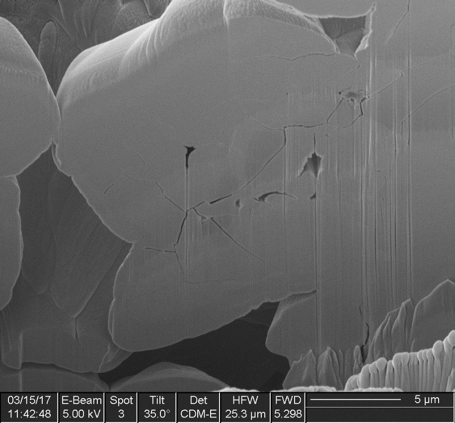
110 DMR 51 ETCHED FIB Preparation (2) 97/135


111 98/135 Multi-Airgap Inductor Core Loss Approximation (1) Solid 10 Air Gaps 20 Air Gaps DMR51 P loss (Watt) N59 P loss (Watt) N87 P loss (Watt) Comp. of Coefficients DMR51, N59, N87

 # Air Gaps # Air Gaps # Air Gaps Ext. of Steinmetz Eq.")
112 99/135 Multi-Airgap Inductor Core Loss Approximation (2) Total Core Loss in Sample with Varying Air Gaps and Test Fixture 500 khz DMR51 N59 N87 P loss (Watt) Linear Fit of Measurements Analytical Approximation of P loss (N) # Air Gaps # Air Gaps # Air Gaps Ext. of Steinmetz Eq. Sufficiently Accurate

113 100/135 Sw. Frequ. Auto-Transformer Approach Multi-Tap Switching Frequ. Multi-Air-Gap Autotransformer Realizing a Multi-Tap Voltage Divider Tap Switch & Series Active Filter for Gen. of Sinus. Output Voltage from Multi-Step Waveform Low-Voltage Power Semiconductors Concept Presented by Cambridge Active Final Power Density Unclear Final: 159W/in 3, 290W/in 3 Shown as Target in Report) Efficiency Unclear (10W of 2kW in Documentation, Equal to Only R = 150mΩ in Total?)
 Multi-Stage Multi-Level Inverter DC-AC-DC (I) Resonant ZVS")
 Voltage-Doubler Rectifier DC-AC (IV) PWM Tap-Selector (V) Output Filter (VI)")
114 101/135 Multi-Tapped Sw. Frequ. Auto-Transformer (1) Multi-Stage Multi-Level Inverter DC-AC-DC (I) Resonant ZVS Half-Bridge (II) Multi-Tapped Auto-Transf. (III) Voltage-Doubler Rectifier DC-AC (IV) PWM Tap-Selector (V) Output Filter (VI) Full-Bridge Unfolder Topology & Operation Different to Approach Presented by Cambridge Active Magnetics


115 102/135 Multi-Tapped Sw. Frequ. Auto-Transformer (2) ηρ-pareto Optimization of the Converter System Efficiency 2kW (97.4% CEC) Power Density 120W/in 3 (7.4kW/dm 3 ) Efficiency of Resonant Multi-Level DC/DC Stage > 99%
116 103/135 Multi-Level Converter Approach Multi-Level PWM Output Voltage - Minimizes Ind. Volume Flying Cap. Conv. No Splitting of DC Inp. Voltage Required Low-Voltage GaN or Si Power Semiconductors Full-Bridge Topology or DC/ AC Buck-Type + Unfolder Basic Patent on FCC Converter Th. Meynard (1991)!

 5 Voltage Levels")


117 104/135 Multi-Level Conv. Approach Flying Cap. Conv. (1) 5 Voltage Levels 320 khz Single-Cell Sw. Frequency 12µF Flying Capacitors Improved Phase-Shift PWM IBB: Internal Balance Booster, 10kΩ S IN1 for Precharge S IN2 for Operation


 (II) Rectifier Operation Under Load, Loss of Mains or")

118 105/135 Multi-Level Conv. Approach Flying Cap. Conv. (2) Analysis of Symmetry of FC Voltages During Start-Up, Shut-Down, Stand-By, Output S.C. Missing Inverter & Rectifier Operation (I) Rectifier Operation No Load, PWM t=0, FCs Discharging over Balance Resistors, Voltage Symmetry Maintained, PWM t=150ms, U out t=300ms (I) (II) Rectifier Operation Under Load, Loss of Mains or PWM Disabled (Load Still Present), FCs Discharging over Diodes Voltage Unbalance, Bridge Leg t=150ms, Dedicated Control Procedure Requ. for Regaining FC Volt. Symmetry (III) Inverter Operation Start-Up form DC-Side, Pre-Charge Resistors t=500ms (II) (III)
119 Optimization of Little-Box 1.0 ηρ-pareto Front TCM vs. Large Ripple PMW The Ideal Switch is Not Enough (!) Design Space Diversity

120 106/135 Multi-Objective Optimization Detailed System Models - Power Buffer/Output Stage/EMI Filter Detailed Multi-Domain Component Models (incl. GaN & SiC) Consideration of Very Large # of Degrees of Freedom Pareto Optimization Shows Trade-Off Between Power Density and Efficiency

 (a) Realized Prototype (b) CeraLink Power Pulsation Buffer (c) X6S Power")
121 107/135 Little Box 1.0 ηρ-performance Limits Multi-Objective Optimization of Little-Box 1.0 (incl. CeraLink X6S) Absolute Performance Limits (I) - DSP/FPGA Power Consumption (II) - Heatsink (1-η) (a) Realized Prototype (b) CeraLink Power Pulsation Buffer (c) X6S Power Pulsation Buffer Further Performance Improvement for Triangular Current Mode (TCM) PWM
 Lower Volume Comp.")


122 108/135 Power Pulsation Buffer (PPB) vs. Electrolytic Capacitor (1) Lower Volume Comp. to Electrolytic Caps only for ΔV/V < 6% No Efficiency Benefit of PPB (!) X6S PPB CeraLink PPB Electrolytic Capacitor Electrolytics Favorable for High Moderate Power Density Electrolytics Show Lower Vol. & Lower Losses if Large ΔV/V is Acceptable (e.g. for PFC Rectifiers)
123 109/135 Power Pulsation Buffer (PPB) vs. Electrolytic Capacitor (2) Analysis for Google Little Box Challenge Specification ΔV/V < 3% Efficiency Benefit of PPB only for ρ > 9kW/dm 3 Electrolytics Favorable for High Moderate Power Density (Δη= +0.5%) Electrolytics Show Lower Vol. & Lower Losses if Large ΔV/V is Acceptable (e.g. for PFC Rectifiers)


")

124 110/135 Little Box TCM PWM Very High Sw. Frequency f S of TCM Around Current Zero Crossings Efficiency Reduction due to Remaining TCM Sw. Losses & Gate Drive Losses Reduction Wide f S -Variation Represents Adv. & Disadvantage for EMI Filter Design (s) Soft-Switching (ZVS) (p-h) Partial Hard Switching (h) Hard-Switching PWM -- Const. Sw. Frequency & Lower Conduction Losses Large Current Rippel -- ZVS in Wide Intervals


125 111/135 Little Box TCM PWM Optimization for GaN GIT & No Interleaving Resulting Opt. Inductance of Output Inductor L=10μH (TCM), L=30μH (PWM) ρ= 11.9kW/dm 3 η = 97.4% ρ= 12.5kW/dm 3 η = 97.4% PWM vs. TCM -- Slightly Higher Max. Power Same Efficiency
126 The Ideal Switch is Not Enough (!)
 Step-by-Step Idealization of the Power Transistors Ideal Switches: k C = 0 (Zero Cond. Losses); k S = 0 (Zero Sw. Losses) Zero Output Cap.")
127 112/135 Little Box Ideal Switches Multi-Objective Optimization of Little-Box 1.0 (X6S Power Pulsation Buffer) Step-by-Step Idealization of the Power Transistors Ideal Switches: k C = 0 (Zero Cond. Losses); k S = 0 (Zero Sw. Losses) Zero Output Cap. and Zero Gate Drive Losses Analysis of Improvement of Given Power Density & Maximum Power Density


128 113/135 Little Box Ideal Switches -- TCM Δη= + ρ= 6kW/dm 3 Main Benefit from Zero Conduction Losses (k C =0) Δη= ρ= 12kW/dm 3 Add. Benefit from Zero Sw. Losses (k S =k C =0) Minor Improvement of Max. Power Density - ρ= 12kW/dm 3 15kW/dm 3 (PPB Cap. & Inductors) Finite Remaining Volume & Losses The Ideal Switch is Not Enough (!)

 Δη= +1.")


129 114/135 Little Box Ideal Switches -- PWM Δη= + ρ= 6kW/dm 3 Benefit from Zero Cond. & Zero Sw. Losses (k S = k C = 0) Δη= ρ= 12kW/dm 3 Benefit from Zero Cond. & Zero Sw. Losses (k S = k C = 0) 50% Improvement of Max. Power Density - ρ= 12kW/dm 3 19kW/dm 3 (PPB & Inductors) Finite Remaining Volume & Losses The Ideal Switch is Not Enough (!)


130 115/135 Little Box Ideal Switches -- PWM ρ = 6kW/dm3 η 99.35% L = 50uH f S = 500kHz or 900kHz L & f S are Independent Variables (Dependent for TCM) Large Design Space Diversity (Mutual Compensation of HF and LF Loss Contributions)
131 Little Box 2.0 DC/ AC Converter + Unfolder PWM vs. TCM incl. Interleaving ηρ-pareto Limits for Non-Ideal Switches Preliminary Exp. Results Final 3D-CAD 250 W/in 3
 Alternative Converter Topology Only Single HF Bridge Leg + 60Hz-Unfolder DC/ AC - Buck Converter + Full-Bridge Unfolder OR HF Half-Bridge & Half-Bridge Unfolder v C0 Easy")
132 116/135 Little Box 2.0 New Converter Topology (1) Alternative Converter Topology Only Single HF Bridge Leg + 60Hz-Unfolder DC/ AC - Buck Converter + Full-Bridge Unfolder OR HF Half-Bridge & Half-Bridge Unfolder v C0 Easy to Generate/Control Higher Conduction Losses Due to FB-Unfolder Lower CM-Noise (DC & n x 120Hz-Comp.) C CM =700nF Allowed for 50mA v AC1 More Difficult to Generate/Control Lower Conduction Losses Higher CM-Noise (DC and n x 120Hz-Comp.) C CM =150nF Allowed for 50mA
 Alternative Converter Topology - DC/ AC - Buck Converter + Unfolder 60Hz-Unfolder (Temporary PWM for Ensuring Continuous Current")
133 117/135 Little Box 2.0 New Converter Topology (2) Alternative Converter Topology - DC/ AC - Buck Converter + Unfolder 60Hz-Unfolder (Temporary PWM for Ensuring Continuous Current Control) TCM or PWM of DC/ AC - Buck-Converter Full Optimization of All Converter Options for Real Switches / X6S Power Pulsation Buffer


134 118/135 Little Box 2.0 Multi-Objective Optimization DC/ AC - Buck Converter + Unfolder & PWM Shows Best Performance Full-Bridge Employs 2 Switching Bridge Legs - Larger Volume & Losses Interleaving Not Advantageous Lower Heatsink Vol. but Larger Total Vol. of Switches and Inductors -- 4D-Interleaving Considered for TCM ρ= 250W/in 3 (15kW/dm 3 η= 98% Efficiency Achievable for Full Optimization
 Full-Bridge")
")
135 119/135 Little Box 2.0 Volume & Loss (P1 5) Full-Bridge Full-Bridge Buck+ Unfolder Buck+ Unfolder Volume Dominated by Heatsink & PPB (Power Pulsation Buffer) Losses for Buck+Unfolder Dominated by Switches & PPB
136 Experimental Results Control Block Diagram Output Voltage/Input Current Quality Efficiency
137 120/135 Little Box 2.0 Control Structure Each Stage (Buck & Unfolder) Controlled with Cascaded Current and Voltage Loop Without Switching of Unfolder Control Like for Conventional Boost PFC Rectifier
 Output Current (10 A/div) Buck Inductor Current (10")

138 121/135 Analysis of DC/ AC -Buck Converter & Unfolder Voltage Zero Crossing Behavior With & Without Switching of Unfolder Output Voltage (200 V/div) Output Current (10 A/div) Buck Inductor Current (10 A/div) Unfolder Voltage (200 V/div) Output Voltage & Current Fully Controlled Around Voltage Zero Crossings Slope of Buck Conv. Outp. Current can be Decreased Adv. for React. Loads (Step-Change of DC Curr.)


139 122/135 Little Box 2.0 Measured Waveforms DC/ AC Buck-Stage Output Voltage & Inductor Current Resistive Load Inductive Load Capacitive Load
140 123/135 Little Box 2.0 Preliminary Efficiency Measurements Performance of First DC/ AC - Buck Converter + Unfolder Prototype PWM Operation Without Power Pulsation Buffer 98% for Res. Load Achievable for Red. of Cond. Losses of PCB (Copper Cross Sect.) & Unfolder (R ds,on )

141 3D-CAD Construction of the Final System 250 W/in 3
142 124/135 Little Box 2.0 Final Mechanical Construction (1) Output Filter PPB Capacitor 60 mm x 50 mm x 45 mm = 135 cm 3 (8.2in 3 ) 14.8 kw/dm 3 (243 W/in 3 )
 Heat Sink + Fans Output Filter PPB Capacitor 60")
143 125/135 Little Box 2.0 Final Mechanical Construction (2) Heat Sink + Fans Output Filter PPB Capacitor 60 mm x 50 mm x 45 mm = 135 cm 3 (8.2in 3 ) 14.8 kw/dm 3 (243 W/in 3 )
 Inductors Output Filter Heat Sink + Fans PPB Capacitor")
144 126/135 Little Box 2.0 Final Mechanical Construction (3) Inductors Output Filter Heat Sink + Fans PPB Capacitor 60 mm x 50 mm x 45 mm = 135 cm 3 (8.2in 3 ) 14.8 kw/dm 3 (243 W/in 3 )
145 127/135 Little Box 2.0 Final Mechanical Construction (4) Power Board Inductors Output Filter Heat Sink + Fans PPB Capacitor 60 mm x 50 mm x 45 mm = 135 cm 3 (8.2in 3 ) 14.8 kw/dm 3 (243 W/in 3 )
 Control Board")

146 128/135 Little Box 2.0 Final Mechanical Construction (5) Control Board Power Board Inductors Output Filter Heat Sink + Fans PPB Capacitor 60 mm x 50 mm x 45 mm = 135 cm 3 (8.2in 3 ) 14.8 kw/dm 3 (243 W/in 3 )

147 Little Box MHz Switching Frequency Performance of Low-μ HF Magnetic Materials Electrolytic Caps vs. Power Pulsation Buffer

 Temp.")

148 129/135 Magnetics Operation Frequency Limit (1) Serious Limitation of Operating Frequency by HF Losses Source: Prof. Albach, 2011 Core Losses High Frequ. & High Operating Temp.) Temp. Dependent Lifetime of the Core Skin-Effect Losses Proximity Effect Losses Adm. Flux Density for given Loss Density Skin-Factor F s for Litz Wires with N Strands

149 130/135 Magnetics Operating Frequency Limit (2) (Modified) Core Material Perform. Factor F 0.75 = B pk.f 0.75 Defined for Def. Core Loss Performance Factor prop. to VA Handling Capability Min. Max. of F 0.75 Little Benefit of Increased f S for Conv. Ferrites in 200kHz 2MHz Peak Performance of Low-μ HF Core 5-10 MHz Source: Hanson et al. ECCE 500mW/cm 3 f S in the MHz-Range Results in Very Low EMI Filter Volume Fair-Rite 67 (μ r =40) All Inductors w. Q= 200
 i = 0 Detection Time Delay Signal Isolator & Gate Drive Time Delays Rel.")

150 131/135 TCM Digital Control / Timing f S > 1MHz Dead Times Required for Res. Transition (ZVS) i = 0 Detection Time Delay Signal Isolator & Gate Drive Time Delays Rel. Large Cond. Low Output Current New High Speed / Low-Volume / Low-Loss i= 0 Detection Concepts Required Integrated Gate Drive w. (Hysteresis) Current Control Functionality Required

151 Source: whiskeybehavior.info Overall Summary
152 132/135 Performance Limits / Future Requirements W/in 3 for Two-Level Bridge Leg + Unfolder W/in 3 for Highly Integrated Multi-Level Approach Isol. Distance Requirements Difficult to Fulfill Fulfilling Ind. Overvoltage Requirements would Signific. Reduce Power Density Low Frequency (20kHz 120kHz) SiC vs. HF (200kHz 1.2MHz) GaN Multi-Cell Concepts for LV Si (GaN) vs. Two-Level SiC (GaN) New Integr. Control Circuits and i=0 Detection for Sw. Frequency >1MHz Integrated Gate Drivers & Switching Cells High Frequency Low Loss Magnetic Materials High Bandwidth Low-Volume Current Sensors Low Loss Ceramic Capacitors Tolerating Large AC Ripple Passives w. Integr. Heat Management and Sensors 3D Packaging New U-I-Probes Required for Ultra-Compact Conv. R&D Spec. Testing Devices Equipped with Integr. Measurement Functions Convergence of Sim. & Measurem. Tools Next Gen. Oscilloscope New Multi-Obj. Multi-Domain Simulation/Optim. Tools
153 References ETH Zurich Other Finalists Non-Finalists General
154 133/135 Publications of ETH Zurich D. Neumayr, D. Bortis, E. Hatipoglu, J. W. Kolar, G. Deboy, New Efficiency Optimal Frequency Modulation (OFM) for High Power Density DC/AC Converter Systems, to be published in Proc. of the International Future Energy Electronics Conference (IFEEC-ECCE Asia), Kaohsiung, Taiwan, June 3-7, D. Neumayr, M. Guacci, D. Bortis, J. W. Kolar, Novel Temperature-Gradient based Calorimetric Measurement Principle to Obtain Soft-Switching Benchmark of GaN and SiC Power Devices, Proceedings of the 29 th IEEE International Symposium on Power Semiconductor Devices and ICs (ISPSD), Sapporo, Japan, May 28 - June 1, D. Rothmund, D. Bortis, J. Huber, D. Biadene, J. W. Kolar, 10kV SiC-Based Bidirectional Soft-Switching Single-Phase AC/DC Converter for Medium-Voltage Solid-State Transformer Applications, Proceedings of the 8 th International Symposium on Power Electronics for Distributed Generation Systems (PEDG), Florianopolis, Brazil, April 17-20, M. Guacci, D. Neumayr, D. Bortis, J. W. Kolar, G. Deboy, Analysis and Design of a Multi-Tapped High-Frequency Auto- Transformer Based Inverter System, Proceedings of the 17 th IEEE Workshop on Control and Modeling for Power Electronics (COMPEL), Trondheim, Norway, June 27-30, D. Neumayr, D. Bortis, J. W. Kolar, Comprehensive Large-Signal Performance Analysis of Ceramic Capacitors for Power Pulsation Buffers, Proceedings of the 17 th IEEE Workshop on Control and Modeling for Power Electronics (COMPEL), Trondheim, Norway, June 27-30, D. Bortis, D. Neumayr, J. W. Kolar, ηρ-pareto Optimization and Comparative Evaluation of Inverter Concepts considered for the GOOGLE Little Box Challenge, Proceedings of the 17 th IEEE Workshop on Control and Modeling for Power Electronics (COMPEL), Trondheim, Norway, June 27-30, J. W. Kolar, D. Bortis, D. Neumayr, The Ideal Switch is Not Enough, Proceedings of the 28 th IEEE International Symposium on Power Semiconductor Devices and ICs (ISPSD), Prague, Czech Republic, June 12-16, D. Bortis, O. Knecht, D. Neumayr, J. W. Kolar, Comprehensive Evaluation of GaN GIT in Low- and High-Frequency Bridge Leg Applications, Proceedings of the 8 th International Power Electronics and Motion Control Conference (IPEMC-ECCE Asia), Hefei, China, May 22-25, D. Neumayr, D. Bortis, J. W. Kolar, Ultra-Compact Power Pulsation Buffer for Single-Phase DC/AC Converter Systems, Proceedings of the 8 th International Power Electronics and Motion Control Conference (IPEMC-ECCE Asia), Hefei, China, May 22-25, 2016.
, 2016. R. Ghosh, M. Srikanth, D. Klikic, M. Wang, R.")
155 134/135 Publications of Other Finalists F. Frebel, O. Bomboir, P. Bleus, D. Rixhon, Transformer-less 2kW Non-Isolated 400VDC/230VAC Single-Stage Micro-Inverter, Proc. of the IEEE Intern. Telecommunications Energy Conference (INTELEC), R. Ghosh, M. Srikanth, D. Klikic, M. Wang, R. Mitova, Novel Active Ripple Filtering Schemes used in the Little Box Inverter, to be published in Proc. of the Intern. Conf. on Power Conv. and Intelligent Motion (PCIM Europe), l. Zhang, R. Born, X. Zhao, J.S. Lai, A High Efficiency Inverter Design for Google Little Box Challenge, Proc. of the IEEE Workshop on Wide Bandgap Power Devices and Applications (WiPDA), C. Zhao, B. Trento, L. Jiang, E. A. Jones, B. Liu, Z. Zhang, D. Costinett, F. Wang, L. M. Tolbert, J. F. Jansen, R. Kress, R. Langley, Design and Implementation of GaN-Based 100-kHz 102-W/in 3 Single-Phase Inverter, IEEE Journal of Emerging and Selected Topics in Power Electronics, vol. 4, no. 3, pp S. Qin, Y. Lei, C. Barth, W. C. Liu, R. C. N. Pilawa-Podgurski, A High Power Density Series-Stacked Energy Buffer for Power Pulsation Decoupling in Single-Phase Converters, to be published in the IEEE Transactions on Power Electronics. T. Menrath, S. Matlok, S. Endres, S. Zelter, B. Eckardt, Mechatronic Design of 2kW SiC DC/AC Converter with 200W/in 3, to be published in Proc. of the Intern. Conf. on Power Conv. and Intelligent Motion (PCIM Europe), General Publications Solaredge Technologies Ltd., Multi-level Inverter, European Patent Application EP A2 (Inventor: I. Yoscovitch), filed March 14, 2014, published Sept. 17, C. P. Henze, H. C. Martin, D. W. Parsley, Zero-voltage Switching in High Frequency Power Converters using Pulse Width Modulation, Proc. of the IEEE Applied Power Electronics Conference (APEC), 1988, pp R. W. Erickson, A. P. Rogers, A Microinverter for Building-Integrated Photovoltaics, Proc. of the IEEE Applied Power Electronics Conference (APEC), 2009, pp M. Pahlevaninezhad, P. Jain, Zero Voltage Switching interleaved Boost AC/DC Converter, US Patent US B2 (May 13, 2014), filed March 9, J. E. Knowles, The Origin of Increase in Magnetic Losses Induced by Machining Ferrites, IEEE Trans. on Magnetics, vol. 11, pp. 1 5, 1975.
156 Biographies of the Authors
 Zurich.")


157 135/135 Johann W. Kolar (F 10) received his Ph.D. degree (summa cum laude) from the Vienna University of Technology, Austria. He is currently a Full Professor and the Head of the Power Electronic Systems Laboratory at the Swiss Federal Institute of Technology (ETH) Zurich. He has proposed numerous novel PWM converter topologies, and modulation and control concepts and has supervised over 60 Ph.D. students. He has published over 750 scientific papers in international journals and conference proceedings, 3 book chapters, and has filed more than 140 patents. He has presented over 20 educational seminars at leading international conferences, has served as IEEE PELS Distinguished Lecturer from 2012 through 2016, and has received 25 IEEE Transactions and Conference Prize Paper Awards, the 2014 IEEE Power Electronics Society R. David Middlebrook Achievement Award, the 2016 IEEE William E. Newell Power Electronics Award, the 2016 IEEE PEMC Council Award, and the ETH Zurich Golden Owl Award for excellence in teaching. He has initiated and/or is the founder of 4 ETH Spin-off companies. The focus of his current research is on ultra-compact and ultra-efficient SiC and GaN converter systems, wireless power transfer, Solid-State Transformers, Power Supplies on Chip, as well as ultra-high speed and ultra-light weight drives, bearingless motors, and energy harvesting. Dominik Neumayr (SM10 ) started his academic education at the University of Applied Sciences (FH) for Automation Engineering in Wels and received the Dipl.-Ing. (FH) degree in He was with the Center for Advanced Power Systems (CAPS) in Tallahassee/Florida working on Power/Controller Hardware-in-the-Loop simulations and control systems design for AC/DC/AC PEBB based converter systems from ABB. He continued his academic education at the Swiss Federal Institute of Technology in Zurich (ETH Zurich) and received the M.Sc. degrees in electrical engineering and information technology in Since spring 2015 he is a PhD student at the Power Electronic Systems (PES) Laboratory, ETH Zurich. His current research focuses on ultra-high power density converter systems. Dominik Bortis (M 08) received the M.Sc. degree in electrical engineering and the Ph.D. degree from the Swiss Federal Institute of Technology (ETH) Zurich, Switzerland, in 2005 and 2008, respectively. In May 2005, he joined the Power Electronic Systems Laboratory (PES), ETH Zurich, as a Ph.D. student. From 2008 to 2011, he has been a Postdoctoral Fellow and from 2011 to 2016 a Research Associate with PES, co-supervising Ph.D. students and leading industry research projects. Since January 2016 Dr. Bortis is heading the newly established research group Advanced Mechatronic Systems at PES.

158 Thank You!
/ Little-Box Challenge
 1/150 / Little-Box Challenge Johann W. Kolar et al. ETH Zurich, Switzerland Power Electronic Systems Laboratory www.pes.ee.ethz.ch 2/150 / Little-Box Challenge All Team Members of ETH Zurich/FH-IZM/Fraza
Power High Frequency
 Power Magnetics @ High Frequency State-of-the-Art and Future Prospects Johann W. Kolar et al. Swiss Federal Institute of Technology (ETH) Zurich Power Electronic Systems Laboratory www.pes.ee.ethz.ch Power
Impact of Magnetics on Power Electronics Converter Performance
 Impact of Magnetics on Power Electronics Converter Performance State-of-the-Art and Future Prospects J. W. Kolar et al. Swiss Federal Institute of Technology (ETH) Zurich Power Electronic Systems Laboratory
VIENNA Rectifier & Beyond...
 VIENNA Rectifier & Beyond... Johann W. Kolar et al. Swiss Federal Institute of Technology (ETH) Zurich Power Electronic Systems Laboratory www.pes.ee.ethz.ch VIENNA Rectifier & Beyond... J. W. Kolar, L.
GaN in Practical Applications
 in Practical Applications 1 CCM Totem Pole PFC 2 PFC: applications and topology Typical AC/DC PSU 85-265 V AC 400V DC for industrial, medical, PFC LLC 12, 24, 48V DC telecomm and server applications. PFC
In Search of Powerful Circuits: Developments in Very High Frequency Power Conversion
 Massachusetts Institute of Technology Laboratory for Electromagnetic and Electronic Systems In Search of Powerful Circuits: Developments in Very High Frequency Power Conversion David J. Perreault Princeton
Voltage Fed DC-DC Converters with Voltage Doubler
 Chapter 3 Voltage Fed DC-DC Converters with Voltage Doubler 3.1 INTRODUCTION The primary objective of the research pursuit is to propose and implement a suitable topology for fuel cell application. The
Miniaturized High-Frequency Integrated Power Conversion for Grid Interface
 Massachusetts Institute of Technology Laboratory for Electromagnetic and Electronic Systems Miniaturized High-Frequency Integrated Power Conversion for Grid Interface David J. Perreault Seungbum Lim David
Single-Loop Control of Buck Power-Pulsation Buffer for AC-DC Converter System
 Single-Loop Control of Buck Power-Pulsation Buffer for AC-DC Converter System Yuri Panov, Milan M. Jovanovi, and Brian T. Irving Power Electronics Laboratory Delta Products Corporation 5101 Davis Drive,
Power Electronics Design 4.0
 IEEE Design Automation for Power Electronics Workshop Power Electronics Design 4.0 Johann W. Kolar Swiss Federal Institute of Technology (ETH) Zurich Power Electronic Systems Laboratory www.pes.ee.ethz.ch
Impact of the Flying Capacitor on the Boost converter
 mpact of the Flying Capacitor on the Boost converter Diego Serrano, Víctor Cordón, Miroslav Vasić, Pedro Alou, Jesús A. Oliver, José A. Cobos Universidad Politécnica de Madrid, Centro de Electrónica ndustrial
Positive to Negative Buck-Boost Converter Using LM267X SIMPLE SWITCHER Regulators
 Positive to Negative Buck-Boost Converter Using LM267X SIMPLE SWITCHER Regulators Abstract The 3rd generation Simple Switcher LM267X series of regulators are monolithic integrated circuits with an internal
Gallium nitride technology in adapter and charger applications
 White Paper Gallium nitride technology in adapter and charger applications The promise of GaN in light of future requirements for power electronics Abstract This paper will discuss the benefits of e-mode
Ultra Compact Three-phase PWM Rectifier
 Ultra Compact Three-phase PWM Rectifier P. Karutz, S.D. Round, M.L. Heldwein and J.W. Kolar Power Electronic Systems Laboratory ETH Zurich Zurich, 8092 SWITZERLAND karutz@lem.ee.ethz.ch Abstract An increasing
MODERN switching power converters require many features
 IEEE TRANSACTIONS ON POWER ELECTRONICS, VOL. 19, NO. 1, JANUARY 2004 87 A Parallel-Connected Single Phase Power Factor Correction Approach With Improved Efficiency Sangsun Kim, Member, IEEE, and Prasad
A Double ZVS-PWM Active-Clamping Forward Converter: Analysis, Design, and Experimentation
 IEEE TRANSACTIONS ON POWER ELECTRONICS, VOL. 16, NO. 6, NOVEMBER 2001 745 A Double ZVS-PWM Active-Clamping Forward Converter: Analysis, Design, and Experimentation René Torrico-Bascopé, Member, IEEE, and
GaN Power ICs at 1 MHz+: Topologies, Technologies and Performance
 GaN Power ICs at 1 MHz+: Topologies, Technologies and Performance PSMA Industry Session, Semiconductors Dan Kinzer, CTO/COO dan.kinzer@navitassemi.com March 2017 Power Electronics: Speed & Efficiency are
PS7516. Description. Features. Applications. Pin Assignments. Functional Pin Description
 Description The PS756 is a high efficiency, fixed frequency 550KHz, current mode PWM boost DC/DC converter which could operate battery such as input voltage down to.9.. The converter output voltage can
Tutorial 2 X-treme Efficiency Power Electronics
 1/114 Tutorial 2 X-treme Efficiency Power Electronics J. W. Kolar Swiss Federal Institute of Technology (ETH) Zurich Power Electronic Systems Laboratory www.pes.ee.ethz.ch 2/114 Deep Green Power Electronics
A Highly Versatile Laboratory Setup for Teaching Basics of Power Electronics in Industry Related Form
 A Highly Versatile Laboratory Setup for Teaching Basics of Power Electronics in Industry Related Form JOHANN MINIBÖCK power electronics consultant Purgstall 5 A-3752 Walkenstein AUSTRIA Phone: +43-2913-411
High Efficiency Flyback Converter Technology
 High Efficiency Flyback Converter Technology U. Boeke ulrich.boeke@philips.com Philips Research Laboratories Aachen, Germany Abstract - Technologies are discussed to realize a DC/DC Flyback converter with
A New 3-phase Buck-Boost Unity Power Factor Rectifier with Two Independently Controlled DC Outputs
 A New 3-phase Buck-Boost Unity Power Factor Rectifier with Two Independently Controlled DC Outputs Y. Nishida* 1, J. Miniboeck* 2, S. D. Round* 2 and J. W. Kolar* 2 * 1 Nihon University Energy Electronics
Gate drive card converts logic level turn on/off commands. Gate Drive Card for High Power Three Phase PWM Converters. Engineer R&D
 Gate Drive Card for High Power Three Phase PWM Converters 1 Anil Kumar Adapa Engineer R&D Medha Servo Drive Pvt. Ltd., India Email: anilkumaradapa@gmail.com Vinod John Department of Electrical Engineering
A High Efficient Integrated Planar Transformer for Primary-Parallel Isolated Boost Converters
 A High Efficient Integrated Planar Transformer for Primary-Parallel Isolated Boost Converters Gokhan Sen 1, Ziwei Ouyang 1, Ole C. Thomsen 1, Michael A. E. Andersen 1, and Lars Møller 2 1. Department of
MP1482 2A, 18V Synchronous Rectified Step-Down Converter
 The Future of Analog IC Technology MY MP48 A, 8 Synchronous Rectified Step-Down Converter DESCRIPTION The MP48 is a monolithic synchronous buck regulator. The device integrates two 30mΩ MOSFETs, and provides
DESCRIPTION FEATURES APPLICATIONS TYPICAL APPLICATION. 500KHz, 18V, 2A Synchronous Step-Down Converter
 DESCRIPTION The is a fully integrated, high-efficiency 2A synchronous rectified step-down converter. The operates at high efficiency over a wide output current load range. This device offers two operation
Design considerations for a Half- Bridge LLC resonant converter
 Design considerations for a Half- Bridge LLC resonant converter Why an HB LLC converter Agenda Configurations of the HB LLC converter and a resonant tank Operating states of the HB LLC HB LLC converter
Recent Approaches to Develop High Frequency Power Converters
 The 1 st Symposium on SPC (S 2 PC) 17/1/214 Recent Approaches to Develop High Frequency Power Converters Location Fireworks Much snow Tokyo Nagaoka University of Technology, Japan Prof. Jun-ichi Itoh Dr.
Designing reliable and high density power solutions with GaN. Created by: Masoud Beheshti Presented by: Paul L Brohlin
 Designing reliable and high density power solutions with GaN Created by: Masoud Beheshti Presented by: Paul L Brohlin What will I get out of this presentation? Why GaN? Integration for System Performance
CHAPTER 3. SINGLE-STAGE PFC TOPOLOGY GENERALIZATION AND VARIATIONS
 CHAPTER 3. SINGLE-STAGE PFC TOPOLOG GENERALIATION AND VARIATIONS 3.1. INTRODUCTION The original DCM S 2 PFC topology offers a simple integration of the DCM boost rectifier and the PWM DC/DC converter.
AT7450 2A-60V LED Step-Down Converter
 FEATURES DESCRIPTION IN Max = 60 FB = 200m Frequency 52kHz I LED Max 2A On/Off input may be used for the Analog Dimming Thermal protection Cycle-by-cycle current limit I LOAD max =2A OUT from 0.2 to 55
Analog Technologies. ATI2202 Step-Down DC/DC Converter ATI2202. Fixed Frequency: 340 khz
 Step-Down DC/DC Converter Fixed Frequency: 340 khz APPLICATIONS LED Drive Low Noise Voltage Source/ Current Source Distributed Power Systems Networking Systems FPGA, DSP, ASIC Power Supplies Notebook Computers
Highly-Reliable Fly-back-based PV Micro-inverter Applying Power Decoupling Capability without Additional Components
 Highly-Reliable Fly-back-based P Micro-inverter Applying Power Decoupling Capability without Additional Components Hiroki Watanabe, Nagaoka University of technology, Japan, hwatanabe@stn.nagaopkaut.ac.jp
Designing High density Power Solutions with GaN Created by: Masoud Beheshti Presented by: Xaver Arbinger
 Designing High density Power Solutions with GaN Created by: Masoud Beheshti Presented by: Xaver Arbinger Topics Why GaN? Integration for Higher System Performance Application Examples Taking GaN beyond
2015 International Future Energy Challenge Topic B: Battery Energy Storage with an Inverter That Mimics Synchronous Generators. Qualification Report
 2015 International Future Energy Challenge Topic B: Battery Energy Storage with an Inverter That Mimics Synchronous Generators Qualification Report Team members: Sabahudin Lalic, David Hooper, Nerian Kulla,
The Quest for High Power Density
 The Quest for High Power Density Welcome to the GaN Era Power Conversion Technology Drivers Key design objectives across all applications: High power density High efficiency High reliability Low cost 2
ACT111A. 4.8V to 30V Input, 1.5A LED Driver with Dimming Control GENERAL DESCRIPTION FEATURES APPLICATIONS TYPICAL APPLICATION CIRCUIT
 4.8V to 30V Input, 1.5A LED Driver with Dimming Control FEATURES Up to 92% Efficiency Wide 4.8V to 30V Input Voltage Range 100mV Low Feedback Voltage 1.5A High Output Capacity PWM Dimming 10kHz Maximum
UNISONIC TECHNOLOGIES CO., LTD UD38252
 UNISONIC TECHNOLOGIES CO., LTD UD38252 38V SYNCHRONOUS BUCK CONVERTER WITH CC/CV DESCRIPTION UTC UD38252 is a wide input voltage, high efficiency Active CC step-down DC/DC converter that operates in either
HM2259D. 2A, 4.5V-20V Input,1MHz Synchronous Step-Down Converter. General Description. Features. Applications. Package. Typical Application Circuit
 HM2259D 2A, 4.5V-20V Input,1MHz Synchronous Step-Down Converter General Description Features HM2259D is a fully integrated, high efficiency 2A synchronous rectified step-down converter. The HM2259D operates
UNISONIC TECHNOLOGIES CO., LTD
 UNISONIC TECHNOLOGIES CO., LTD 38V 5A SYNCHRONOUS BUCK CONVERTER DESCRIPTION The UTC UD38501 is a monolithic synchronous buck regulator. The device integrates internal high side and external low side power
AT V Synchronous Buck Converter
 38V Synchronous Buck Converter FEATURES DESCRIPTION Wide 8V to 38V Operating Input Range Integrated two 140mΩ Power MOSFET Switches Feedback Voltage : 220mV Internal Soft-Start / VFB Over Voltage Protection
Application of GaN Device to MHz Operating Grid-Tied Inverter Using Discontinuous Current Mode for Compact and Efficient Power Conversion
 IEEE PEDS 2017, Honolulu, USA 12-15 December 2017 Application of GaN Device to MHz Operating Grid-Tied Inverter Using Discontinuous Current Mode for Compact and Efficient Power Conversion Daichi Yamanodera
MP1472 2A, 18V Synchronous Rectified Step-Down Converter
 The Future of Analog IC Technology MP472 2A, 8 Synchronous Rectified Step-Down Converter DESCRIPTION The MP472 is a monolithic synchronous buck regulator. The device integrates a 75mΩ highside MOSFET and
Designing a 99% Efficient Totem Pole PFC with GaN. Serkan Dusmez, Systems and applications engineer
 Designing a 99% Efficient Totem Pole PFC with GaN Serkan Dusmez, Systems and applications engineer 1 What will I get out of this session? Purpose: Why GaN Based Totem-pole PFC? Design guidelines for getting
Ultra Compact Three-Phase Rectifier with Electronic Smoothing Inductor
 Ultra Compact ThreePhase Rectifier with Electronic Smoothing Inductor K. Mino, M.. Heldwein, J. W. Kolar Swiss Federal Institute of Technology (ETH) Zurich Power Electronic Systems aboratory ETH Zentrum
SiC MOSFETs Based Split Output Half Bridge Inverter: Current Commutation Mechanism and Efficiency Analysis
 SiC MOSFETs Based Split Output Half Bridge Inverter: Current Commutation Mechanism and Efficiency Analysis Helong Li, Stig Munk-Nielsen, Szymon Bęczkowski, Xiongfei Wang Department of Energy Technology
Improvements of LLC Resonant Converter
 Chapter 5 Improvements of LLC Resonant Converter From previous chapter, the characteristic and design of LLC resonant converter were discussed. In this chapter, two improvements for LLC resonant converter
LSP5502 2A Synchronous Step Down DC/DC Converter
 FEATURES 2A Output Current Wide 4.5V to 27V Operating Input Range Integrated 20mΩ Power MOSFET Switches Output Adjustable from 0.925V to 24V Up to 96% Efficiency Programmable Soft-Start Stable with Low
CEP8113A Rev 2.0, Apr, 2014
 Wide-Input Sensorless CC/CV Step-Down DC/DC Converter FEATURES 42V Input Voltage Surge 40V Steady State Operation Up to 3.5A output current Output Voltage 2.5V to 10V Resistor Programmable Current Limit
ANP012. Contents. Application Note AP2004 Buck Controller
 Contents 1. AP004 Specifications 1.1 Features 1. General Description 1. Pin Assignments 1.4 Pin Descriptions 1.5 Block Diagram 1.6 Absolute Maximum Ratings. Hardware.1 Introduction. Typical Application.
Study of a 3kW High-Efficient Wide-Bandgap DC- DC Power Converter for Solar Power Integration in 400V DC Distribution Networks
 IEEE PEDS 2017, Honolulu, USA 12 15 December 2017 Study of a 3kW High-Efficient Wide-Bandgap DC- DC Power Converter for Solar Power Integration in 400V DC Distribution Networks Yucheng Zhang, Yashwanth
Design of EMI Filters for DC-DC converter
 Design of EMI Filters for DC-DC converter J. L. Kotny*, T. Duquesne**, N. Idir** Univ. Lille Nord de France, F-59000 Lille, France * USTL, F-59650 Villeneuve d Ascq, France ** USTL, L2EP, F-59650 Villeneuve
FAN MHz TinyBoost Regulator with 33V Integrated FET Switch
 FAN5336 1.5MHz TinyBoost Regulator with 33V Integrated FET Switch Features 1.5MHz Switching Frequency Low Noise Adjustable Output Voltage Up to 1.5A Peak Switch Current Low Shutdown Current:
GENERALLY, a single-inductor, single-switch boost
 IEEE TRANSACTIONS ON POWER ELECTRONICS, VOL. 19, NO. 1, JANUARY 2004 169 New Two-Inductor Boost Converter With Auxiliary Transformer Yungtaek Jang, Senior Member, IEEE, Milan M. Jovanović, Fellow, IEEE
Generating Isolated Outputs in a Multilevel Modular Capacitor Clamped DC-DC Converter (MMCCC) for Hybrid Electric and Fuel Cell Vehicles
 for Hybrid Electric and Fuel Cell Vehicles") Generating Isolated Outputs in a Multilevel Modular Capacitor Clamped DC-DC Converter (MMCCC) for Hybrid Electric and Fuel Cell Vehicles Faisal H. Khan 1, Leon M. Tolbert 2 1 Electric Power Research Institute
Generating Isolated Outputs in a Multilevel Modular Capacitor Clamped DC-DC Converter (MMCCC) for Hybrid Electric and Fuel Cell Vehicles Faisal H. Khan 1, Leon M. Tolbert 2 1 Electric Power Research Institute
IN A CONTINUING effort to decrease power consumption
 184 IEEE TRANSACTIONS ON POWER ELECTRONICS, VOL. 14, NO. 1, JANUARY 1999 Forward-Flyback Converter with Current-Doubler Rectifier: Analysis, Design, and Evaluation Results Laszlo Huber, Member, IEEE, and
ACE726C. 500KHz, 18V, 2A Synchronous Step-Down Converter. Description. Features. Application
 Description The is a fully integrated, high-efficiency 2A synchronous rectified step-down converter. The operates at high efficiency over a wide output current load range. This device offers two operation
4.5V to 32V Input High Current LED Driver IC For Buck or Buck-Boost Topology CN5816. Features: SHDN COMP OVP CSP CSN
 4.5V to 32V Input High Current LED Driver IC For Buck or Buck-Boost Topology CN5816 General Description: The CN5816 is a current mode fixed-frequency PWM controller for high current LED applications. The
BIDIRECTIONAL CURRENT-FED FLYBACK-PUSH-PULL DC-DC CONVERTER
 BIDIRECTIONAL CURRENT-FED FLYBACK-PUSH-PULL DC-DC CONVERTER Eduardo Valmir de Souza and Ivo Barbi Power Electronics Institute - INEP Federal University of Santa Catarina - UFSC www.inep.ufsc.br eduardovs@inep.ufsc.br,
Unlocking the Power of GaN PSMA Semiconductor Committee Industry Session
 Unlocking the Power of GaN PSMA Semiconductor Committee Industry Session March 24 th 2016 Dan Kinzer, COO/CTO dan.kinzer@navitassemi.com 1 Mobility (cm 2 /Vs) EBR Field (MV/cm) GaN vs. Si WBG GaN material
Impulse Transformer Based Secondary-Side Self- Powered Gate-Driver for Wide-Range PWM Operation of SiC Power MOSFETs
 Impulse Transformer Based Secondary-Side Self- Powered Gate-Driver for Wide-Range PWM Operation of SiC Power MOSFETs Jorge Garcia Dept of Electrical Engineering, University of Oviedo LEMUR Research Group
Cree PV Inverter Tops 1kW/kg with All-SiC Design
 Cree PV Inverter Tops 1kW/kg with All-SiC Design Alejandro Esquivel September, 2014 Power Forum 2014 (Bologna) presentation sponsored by: Presentation Outline 1. Meeting an Industry Need a) 1kW/Kg b) No
AN IMPROVED ZERO-VOLTAGE-TRANSITION INTERLEAVED BOOST CONVERTER WITH HIGH POWER FACTOR
 AN IMPROVED ZERO-VOLTAGE-TRANSITION INTERLEAVED BOOST CONVERTER WITH HIGH POWER FACTOR Naci GENC 1, Ires ISKENDER 1 1 Gazi University, Faculty of Engineering and Architecture, Department of Electrical
Impact of Fringing Effects on the Design of DC-DC Converters
 Impact of Fringing Effects on the Design of DC-DC Converters Michael Seeman, Ph.D. Founder / CEO. 2018 APEC PSMA/PELS 2018. Outline Fringe-field loss: What does a power supply designer need to know? Which
CEP8101A Rev 1.0, Apr, 2014
 Wide-Input Sensorless CC/CV Step-Down DC/DC Converter FEATURES 42V Input Voltage Surge 40V Steady State Operation Up to 2.1A output current Output Voltage 2.5V to 10V Resistor Programmable Current Limit
ADT7350. General Description. Features. Applications. Typical Application Circuit. Sep / Rev. 0.
 General Description The ADT7350 is a step-down converter with integrated switching MOSFET. It operates wide input supply voltage range from 4.5V to 24V with 1.2A peak output current. It includes current
Si, SiC and GaN Power Devices: An Unbiased View on Key Performance Indicators
 2016 IEEE Proceedings of the 62nd IEEE International Electron Devices Meeting (IEDM 2016), San Francisco, USA, December 3-7, 2016 Si, SiC and GaN Power Devices: An Unbiased View on Key Performance Indicators
idesyn id8802 2A, 23V, Synchronous Step-Down DC/DC
 2A, 23V, Synchronous Step-Down DC/DC General Description Applications The id8802 is a 340kHz fixed frequency PWM synchronous step-down regulator. The id8802 is operated from 4.5V to 23V, the generated
Op Amp Booster Designs
 Op Amp Booster Designs Although modern integrated circuit operational amplifiers ease linear circuit design, IC processing limits amplifier output power. Many applications, however, require substantially
2A,4.5V-21V Input,500kHz Synchronous Step-Down Converter FEATURES GENERAL DESCRIPTION APPLICATIONS TYPICAL APPLICATION
 2A,4.5-21 Input,500kHz Synchronous Step-Down Converter FEATURES High Efficiency: Up to 96% 500KHz Frequency Operation 2A Output Current No Schottky Diode Required 4.5 to 21 Input oltage Range 0.8 Reference
IN THE high power isolated dc/dc applications, full bridge
 354 IEEE TRANSACTIONS ON POWER ELECTRONICS, VOL. 21, NO. 2, MARCH 2006 A Novel Zero-Current-Transition Full Bridge DC/DC Converter Junming Zhang, Xiaogao Xie, Xinke Wu, Guoliang Wu, and Zhaoming Qian,
Presentation Content Review of Active Clamp and Reset Technique in Single-Ended Forward Converters Design Material/Tools Design procedure and concern
 Active Clamp Forward Converters Design Using UCC2897 Hong Huang August 2007 1 Presentation Content Review of Active Clamp and Reset Technique in Single-Ended Forward Converters Design Material/Tools Design
RT9270 High Performance, Low Noise Boost Converter General Description Features 90% Efficiency IN Operating Range: 2.3V to 5.5V 1.9A, 0.
 High Performance, Low Noise Boost Converter General Description The is a high performance, low noise, fixed frequency step up DC-DC Converter. The converters input voltage ranging.3v to 5.5V into output
MICROCONTROLLER BASED BOOST PID MUNAJAH BINTI MOHD RUBAEE
 MICROCONTROLLER BASED BOOST PID MUNAJAH BINTI MOHD RUBAEE This thesis is submitted as partial fulfillment of the requirement for the award of Bachelor of Electrical Engineering (Power System) Faculty of
Design Considerations for 12-V/1.5-V, 50-A Voltage Regulator Modules
 776 IEEE TRANSACTIONS ON POWER ELECTRONICS, VOL. 16, NO. 6, NOVEMBER 2001 Design Considerations for 12-V/1.5-V, 50-A Voltage Regulator Modules Yuri Panov and Milan M. Jovanović, Fellow, IEEE Abstract The
MIC2296. General Description. Features. Applications. High Power Density 1.2A Boost Regulator
 High Power Density 1.2A Boost Regulator General Description The is a 600kHz, PWM dc/dc boost switching regulator available in a 2mm x 2mm MLF package option. High power density is achieved with the s internal
Boundary Mode Offline LED Driver Using MP4000. Application Note
 The Future of Analog IC Technology AN046 Boundary Mode Offline LED Driver Using MP4000 Boundary Mode Offline LED Driver Using MP4000 Application Note Prepared by Zheng Luo March 25, 2011 AN046 Rev. 1.0
Design and Characterization of a Three-Phase Multichip SiC JFET Module
 Design and Characterization of a Three-Phase Multichip SiC JFET Module Fan Xu* fxu6@utk.edu Jing Wang* jwang50@utk.edu Dong Jiang* djiang4@utk.edu Fred Wang* fred.wang@utk.edu Leon Tolbert* tolbert@utk.edu
1. The current-doubler rectifier can be used to double the load capability of isolated dc dc converters with bipolar secondaryside
 Highlights of the Chapter 4 1. The current-doubler rectifier can be used to double the load capability of isolated dc dc converters with bipolar secondaryside voltage. Some industry-generated papers recommend
ADT7350. General Description. Applications. Features. Typical Application Circuit. Aug / Rev. 0.
 General Description The ADT7350 is a step-down converter with integrated switching MOSFET. It operates wide input supply voltage range from 4.5V to 24V with 1.2A peak output current. It includes current
Achieving High Power Density Designs in DC-DC Converters
 Achieving High Power Density Designs in DC-DC Converters Agenda Marketing / Product Requirement Design Decision Making Translating Requirements to Specifications Passive Losses Active Losses Layout / Thermal
MP2305 2A, 23V Synchronous Rectified Step-Down Converter
 The Future of Analog IC Technology MP305 A, 3 Synchronous Rectified Step-Down Converter DESCRIPTION The MP305 is a monolithic synchronous buck regulator. The device integrates 30mΩ MOSFETS that provide
WD3122EC. Descriptions. Features. Applications. Order information. High Efficiency, 28 LEDS White LED Driver. Product specification
 High Efficiency, 28 LEDS White LED Driver Descriptions The is a constant current, high efficiency LED driver. Internal MOSFET can drive up to 10 white LEDs in series and 3S9P LEDs with minimum 1.1A current
TDA Power Factor Controller. IC for High Power Factor and Active Harmonic Filtering
 Power Factor Controller IC for High Power Factor and Active Harmonic Filtering TDA 4817 Advance Information Bipolar IC Features IC for sinusoidal line-current consumption Power factor approaching 1 Controls
Conventional Single-Switch Forward Converter Design
 Maxim > Design Support > Technical Documents > Application Notes > Amplifier and Comparator Circuits > APP 3983 Maxim > Design Support > Technical Documents > Application Notes > Power-Supply Circuits
MegaCube. G. Ortiz, J. Biela, J.W. Kolar. Swiss Federal Institute of Technology (ETH) Zurich Power Electronic Systems Laboratory
 Zurich Power Electronic Systems Laboratory") MegaCube G. Ortiz, J. Biela, J.W. Kolar Swiss Federal Institute of Technology (ETH) Zurich Power Electronic Systems Laboratory www.pes.ee.ethz.ch Offshore Wind Power Generation: DC v/s AC Transmission
MegaCube G. Ortiz, J. Biela, J.W. Kolar Swiss Federal Institute of Technology (ETH) Zurich Power Electronic Systems Laboratory www.pes.ee.ethz.ch Offshore Wind Power Generation: DC v/s AC Transmission
10kW Three-phase SiC PFC Rectifier
 www.onsemi.com 10kW Three-phase SiC PFC Rectifier SEMICON EUROPA, Nov 13-18, 2018, Munich, Germany Contents General PFC Concept 3 Phase System and PFC Control Simulation Understanding the losses 3 Phase
Features. RAMP Feed Forward Ramp/ Volt Sec Clamp Reference & Isolation. Voltage-Mode Half-Bridge Converter CIrcuit
 MIC3838/3839 Flexible Push-Pull PWM Controller General Description The MIC3838 and MIC3839 are a family of complementary output push-pull PWM control ICs that feature high speed and low power consumption.
Power Factor Correction of LED Drivers with Third Port Energy Storage
 Power Factor Correction of LED Drivers with Third Port Energy Storage Saeed Anwar Mohamed O. Badawy Yilmaz Sozer sa98@zips.uakron.edu mob4@zips.uakron.edu ys@uakron.edu Electrical and Computer Engineering
SGM % Efficient Synchronous Step-Up Converter with 1.1A Switch
 GERAL DESCRIPTION The SGM0 is a constant frequency, current mode, synchronous step-up switching regulator. It can be used for generating V at 00mA from a.v rail or a Li-Ion battery. High switching frequency
1.0MHz,24V/2.0A High Performance, Boost Converter
 1.0MHz,24V/2.0A High Performance, Boost Converter General Description The LP6320C is a 1MHz PWM boost switching regulator designed for constant-voltage boost applications. The can drive a string of up
MP2307 3A, 23V, 340KHz Synchronous Rectified Step-Down Converter
 The Future of Analog IC Technology TM TM MP307 3A, 3, 340KHz Synchronous Rectified Step-Down Converter DESCRIPTION The MP307 is a monolithic synchronous buck regulator. The device integrates 00mΩ MOSFETS
Improvement of Light Load Efficiency for Buck- Boost DC-DC converter with ZVS using Switched Auxiliary Inductors
 Improvement of ight oad Efficiency for Buck- Boost DC-DC converter with ZVS using Switched Auxiliary Inductors Hayato Higa Dept. of Energy Environment Science Engineering Nagaoka University of Technology
MP3115 High-Efficiency, Single-Cell Alkaline, 1.3MHz Synchronous Step-up Converter with Output Disconnect
 The Future of Analog IC Technology MP3115 High-Efficiency, Single-Cell Alkaline, 1.3MHz Synchronous Step-up Converter with Output Disconnect DESCRIPTION The MP3115 is a synchronous, fixed frequency, current
Features MIC2193BM. Si9803 ( 2) 6.3V ( 2) VDD OUTP COMP OUTN. Si9804 ( 2) Adjustable Output Synchronous Buck Converter
 6.3V ( 2) VDD OUTP COMP OUTN. Si9804 ( 2) Adjustable Output Synchronous Buck Converter") MIC2193 4kHz SO-8 Synchronous Buck Control IC General Description s MIC2193 is a high efficiency, PWM synchronous buck control IC housed in the SO-8 package. Its 2.9V to 14V input voltage range allows
MIC2193 4kHz SO-8 Synchronous Buck Control IC General Description s MIC2193 is a high efficiency, PWM synchronous buck control IC housed in the SO-8 package. Its 2.9V to 14V input voltage range allows
SGM % Efficient Synchronous Step-Up Converter with 1.1A Switch
 GERAL DESCRIPTION The SGM0 is a constant frequency, current mode, synchronous step-up switching regulator. Its output currents can go as high as 7mA while using a single-cell alkaline, and discharge it
THE converter usually employed for single-phase power
 82 IEEE TRANSACTIONS ON INDUSTRIAL ELECTRONICS, VOL. 46, NO. 1, FEBRUARY 1999 A New ZVS Semiresonant High Power Factor Rectifier with Reduced Conduction Losses Alexandre Ferrari de Souza, Member, IEEE,
RT9277A/B. High Performance, Low Noise Boost Converter. Preliminary. Features. General Description. Applications. Ordering Information
 High Performance, Low Noise Boost Converter General Description The is a high performance, low noise, fixed frequency step up DC-DC Converter. The converters input voltage ranging.5v to 5.5V into output
A HIGH EFFICIENT IMPROVED SOFT SWITCHED INTERLEAVED BOOST CONVERTER
 A HIGH EFFICIENT IMPROVED SOFT SWITCHED INTERLEAVED BOOST CONVERTER A.Karthikeyan, 1 S.Athira, 2 PSNACET, Dindigul, India. janakarthi@rediffmail.com, athiraspecial@gmail.com ABSTRACT In this paper an improved
23V, 3A, 340KHz Synchronous Step-Down DC/DC Converter
 23V, 3A, 340KHz Synchronous Step-Down DC/DC Converter Description The is a synchronous step-down DC/DC converter that provides wide 4.5V to 23V input voltage range and 3A continuous load current capability.