Impact of Magnetics on Power Electronics Converter Performance
|
|
|
- Austen Sullivan
- 5 years ago
- Views:
Transcription

 Zurich Power")
1 Impact of Magnetics on Power Electronics Converter Performance State-of-the-Art and Future Prospects J. W. Kolar et al. Swiss Federal Institute of Technology (ETH) Zurich Power Electronic Systems Laboratory Magnetics Committee
2 Impact of Magnetics on Power Electronics Converter Performance State-of-the-Art and Future Prospects J. W. Kolar, F. Krismer, M. Leibl, D. Neumayr, L. Schrittwieser, D. Bortis Swiss Federal Institute of Technology (ETH) Zurich Power Electronic Systems Laboratory Magnetics Committee
3 1/61 Outline Performance Trends Design Space / Performance Space Performance Characteristics of Key Components Feasible Performance Space / Pareto Front Losses Due to Local Stresses in Ferrite Surfaces The Ideal Switch is NOT Enough! Challenges in MV/MF Power Conversion Future Prospects E. Hoene / FH IZM St. Hoffmann / FH IZM M. Kasper E. Hatipoglu P. Papamanolis Th. Guillod J. Miniböck Acknowledgement U. Badstübner
4 Introduction Converter Performance Indicators Design Space / Performance Space
![2/61 Power Electronics Converter Performance Indicators Environmental Impact [kg Fe /kw] [kg Cu /kw] [kg Al /kw] [cm 2 Si](/docs-images/93/114425407/images/5-4.jpg "/kw] Power Density [kw/dm 3 ] Power per Unit Weight [kw/kg] Relative Costs [kw/$] Relative Losses [%] Failure Rate [h -1")
5 2/61 Power Electronics Converter Performance Indicators Environmental Impact [kg Fe /kw] [kg Cu /kw] [kg Al /kw] [cm 2 Si /kw] Power Density [kw/dm 3 ] Power per Unit Weight [kw/kg] Relative Costs [kw/$] Relative Losses [%] Failure Rate [h -1 ]

6 3/61 Performance Limits (1) Example of Highly-Compact 1-Ф PFC Rectifier Two Interleaved 1.6kW Systems CoolMOS SiC Diodes P O = 3.2kW U N = 230V±10% U O = 400V f P = 450kHz ± 50kHz η = ρ = 5.5 kw/dm 3 High Power Low Efficiency Trade-Off Between Power Density and Efficiency

7 4/61 Performance Limits (2) Example of Highly-Efficient 1-Ф PFC Rectifier Two Interleaved 1.6kW Systems P O = 3.2kW U N = 230V±10% U O = 365V CoolMOS SiC Diodes f P = 33kHz ± 3kHz η = ρ = 1.1 kw/dm 3 High Low Power Density Trade-Off Between Power Density and Efficiency
8 5/61 Abstraction of Power Converter Design Performance Space Design Space Mapping of Design Space into Performance Space

9 Derivation of η-ρ- Performance Limit of Converter Systems Component η-ρ-characteristics Converter η-ρ-pareto Front

10 6/61 Derivation of the η-ρ- Performance Limit Example of DC/AC Converter System Key Components Storage Capacitor Semiconductors & Heatsink Output Inductor Auxiliary Supply Construct η -ρ -Characteristics of Key Components Determine Feasible System Performance Space


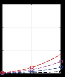
11 7/61 η-ρ- Characteristic of Energy Storage Electrolytic Capacitors Losses (ESR) Neglected Energy Storage Defines a Converter Limit ρ max ρ C


12 8/61 Remark Active Power Pulsation Buffer Large Voltage Fluctuation Foil or Ceramic Capacitor Buck-Type (Lower Voltage Levels) or Boost-Type DC/DC Interface Converter CeraLink Significantly Lower Overall Volume Compared to Electrolytic Capacitor BUT Lower Efficiency


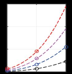
13 9/61 η-ρ- Characteristic of Power Semiconductors / Heatsink Semiconductor Losses are Translating into Heat Sink Volume Heatsink Characterized by Cooling System Performance Index (CSPI) Volume of Semiconductors Neglected Heatsink Defines a Converter Limit ρ ρ H

14 10/61 Remark Selection of Semiconductor Chip Area Optimize Chip for Minimum Sw. and Conduction Losses Loss Minimum Dependent on Sw. Frequency Influence of Power Semiconductor FOM Larger Losses for Higher Sw. Frequency Large A Si / Low Cond. Losses only for ZVS Extreme Efficiency Only for Low Sw. Frequ.

15 11/61 η-ρ- Characteristic of Auxiliary Supply Power Consumption of Control, Fans etc. Independent of Output Power Power Density Relates Volume of Aux. Supply to Total (!) Output Power Auxiliary Power Defines Efficiency Limit
 η-ρ Characteristic w/o Magnetics Higher Sw. Frequ.")
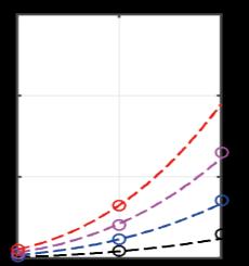
16 12/61 η-ρ- Characteristic of Storage + Heatsink + Auxiliary Overall Power Density Lower than Lowest Individual Power Density Total Efficiency Lower than Lowest Individual Efficiency Example of Heat Sink + Storage (No Losses) η-ρ Characteristic w/o Magnetics Higher Sw. Frequ. Leads to Larger Volume


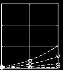
17 13/61 η-ρ- Characteristic of Inductor (1) Inductor Flux Swing Defined by DC Voltage & Sw. Frequ. (& Mod. Index) -1 -Order Approx. of Volume-Dependency of Losses 0 -Order Approx. (N opt ) Losses are Decreasing with Increasing Linear Dimensions & Sw. Frequency

18 14/61 η-ρ- Characteristic of Inductor (2) Loss-Opt. of Single-Airgap N87 Core Inductor Consideration of HF Winding and Core Losses Thermal Limit Acc. To Natural Convection Assumption: Given Magnetic Core Higher Sw. Frequ. Lower Min. Ind. Losses Overall Loss Red. Limited by Semicond. Sw. Losses

19 15/61 η-ρ- Characteristic of Inductor (3) Overall Power Density Lower than Lowest Individual Power Density Total Efficiency Lower than Individual Efficiency Natural Convection η-ρ Characteristic of Inductors Higher Sw. Frequ. Leads to Lower Vol. Allowed Losses Defined by Cooling
 Example of Highly-Compact 3-Ф PFC Rectifier Nat. Conv.")
20 16/61 Remark Natural Conv. Thermal Limit (1) Example of Highly-Compact 3-Ф PFC Rectifier Nat. Conv. Cooling of Inductors and EMI Filter Semiconductors Mounted on Cold Plate P O = 10 kw U N = 230V AC ±10% f N = 50Hz or Hz U O = 800V DC f P = 250kHz ρ = 10 kw/dm η = 96.2% Systems with f P = 72/250/500/1000kHz Factor 10 in f P Factor 2 in Power Density
21 17/61 Remark Natural Conv. Thermal Limit (2) Example of Highly-Compact 3-Ф PFC Rectifier Nat. Conv. Cooling of Inductors and EMI Filter Semiconductors Mounted on Cold Plate P O = 10 kw U N = 230V AC ±10% f N = 50Hz or Hz U O = 800V DC f P = 250kHz ρ = 10 kw/dm η = 96.2% Systems with f P = 72/250/500/1000kHz Factor 10 in f P Factor 2 in Power Density
 Consideration of Different Shape Factors Constant Power to be Processed Source: D.B.")

22 18/61 Remark Natural Conv. Thermal Limit (3) Consideration of Different Shape Factors Constant Power to be Processed Source: D.B. Go Notre Dame Univ. SYS / SYS,CUBE Natural Convection k= CUBE: 0 k= k = h / a 5 k=5 All Sides Single Side Planar Structure Facilitate High Power Density Cube Shape Shows Low Surface Given Volume Nat. Conv. Requires Min. Thickness of Boundary Layer (>5mm) which is often Not Considered

23 19/61 η-ρ- Characteristic of Inductor (4) Natural Convection Heat Transfer Seriously Limits Allowed Inductor Losses Higher Power Density Through Explicit Inductor Heatsink Natural Convection Explicit Heatsink Primary/Secondary HTC Primary/Secondary Winding HTC Winding HTC HTC HTC HTC Core Core HTC Heat Sink HTC Heat Sink Air Flow Fan Air Flow Fan Heat Transfer Coefficients k L and α L Dependent on Max. Surface Temp. / Heatsink Temp. Water Cooling Facilitates Extreme (Local) Power Densities
 & Heatsink for Transformer Cooling Magn.")
24 20/61 Remark Example for Explicit Heatsink for Magn. Component Phase-Shift Full-Bridge Isolated DC/DC Converter with Current-Doubler Rectifier Heat Transfer Component (HTC) & Heatsink for Transformer Cooling Magn. Integration of Current-Doubler Inductors P O = 5kW U in = 400V U O = 48 56V (300mV pp ) T a = 45 C f P = 120kHz 9 kw/dm3 (148W/in %
 & Heatsink for Transformer Cooling Magn.")
25 21/61 Remark Example for Explicit Heatsink for Magn. Component Phase-Shift Full-Bridge Isolated DC/DC Converter with Current-Doubler Rectifier Heat Transfer Component (HTC) & Heatsink for Transformer Cooling Magn. Integration of Current-Doubler Inductors P O = 5kW U in = 400V U O = 48 56V (300mV pp ) T a = 45 C f P = 120kHz 9 kw/dm3 (148W/in %
26 22/61 Remark Dependency of Efficiency on Load Condition Assumption of Purely Ohmic Losses Quadratic Dependency of Losses on Output Power Quadratic Reduction of Losses with Output Power High Part Load Efficiency Despite Low Rated Load Efficiency (Thermal. Rated Load)


27 23/61 Overall Converter η-ρ- Characteristics Combination of Storage/Heatsink/Auxiliary & Inductor Characteristics Sw. Frequ. Indicates Related Loss and Power Density Values! Low Semiconductor Sw. Losses High Semiconductor Sw. Losses Low Sw. Losses / High Sw. Frequ. / Small Heatsink / Small Ind. / High Total Power Density High Sw. Losses / Low Sw. Frequ. / Large Heatsink / Large Ind. / Low Total Power Density

28 24/61 Overall Converter η-ρ- Characteristics Summary Inductor Takes Significant Influence on Efficiency/Power Density Characteristic Converters with Inductor Very Low Losses Only for Very Low Power Density Conv. with No Inductor Very High Power Low Losses Inductor Defines Power Density Limit of Ultra-Efficient Converter Systems! Eff./Power Density Characteristic Strongly Dependent on Converter Type! Variable Speed Drive Inverters No Inductor (Built into AC Machine) Very High Power Density

29 Reduction of Inductor Requirement Parallel Interleaving Series Interleaving


30 25/61 Inductor Volt-Seconds / Size Inductor Volt-Seconds are Determining the Local Flux Density Ampl. Output Inductor has to be Considered Part of the EMI Filter Multi-Level Converters Allow to Decrease Volt-Seconds by Factor of N 2 Calculation of Equivalent Noise Sw. Frequency (2 nd Bridge Leg w. Fund. Frequ.) EMI Filter Design Can be Based on Equiv. Noise Voltage


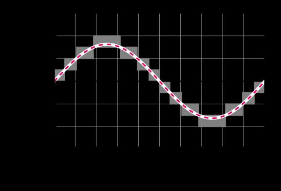
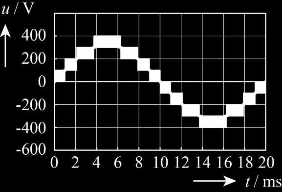
31 26/61 Reduction of Inductor Volt-Seconds / Size Multi-Level Characteristic through Series-Interleaving Multi-Level Characteristic through Parallel Interleaving Identical Spectral Properties for Both Concepts Series Interleaving Avoids Coupling Inductor of Parallel Interleaving!
32 27/61 Multi-Level Converter Approach Multi-Level PWM Output Voltage Minimizes Ind. Volume Flying Cap. Conv. No Splitting of DC Inp. Voltage Required Low-Voltage GaN or Si Power Semiconductors Full-Bridge Topology or DC/ AC Buck-Type + Unfolder Basic Patent on FCC Converter Th. Meynard (1991)!


33 28/61 Example of 5-Level Flying Capacitor Converter 5 Output Voltage Levels 320 khz Single-Cell Sw. Frequency 12µF Flying Capacitors Improved Phase-Shift PWM S IN1 for Precharge S IN2 for Operation IBB: Internal Balance Booster, 10kΩ Very Small Output Inductor Voltage Balancing Challenging in certain Operating Conditions

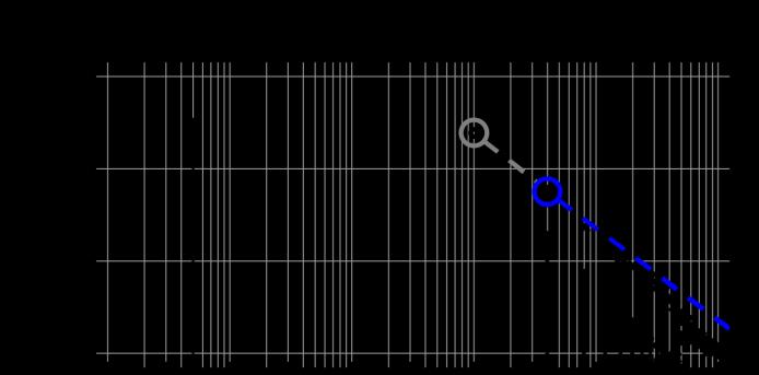
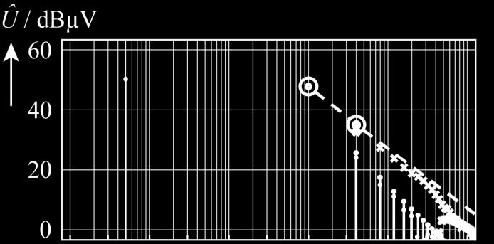
34 29/61 Required EMI Filter Attenuation (1) Higher Switching Frequency Increases Required Attenuation
35 30/61 Required EMI Filter Attenuation (2) Higher Switching Frequ. Increases Required Att. Only Option f P >500kHz
36 Transformers Optimal Operating Frequency Example of MF/MV Transformer


37 31/61 Transformer Operation Frequency Limit Dependency of Volume and Weight on Frequency Higher Frequency Results in Smaller Transformer Size only Up to Certain Limit (Prox. Eff.) Defined Frequencies for Min. Vol. or Min. Weight Dep. On Strand Diam. & Wdg Width Source: Philips 100Vx1A 1.1 Transformers, 3F3, 30 C Temp. Rise
 AC/DC and")

38 32/61 Future Direct MV Supply of 400V DC Distribution of Datacenters Reduces Losses & Footprint / Improves Reliability & Power Quality Unidirectional Multi-Cell Solid-State Transformer (SST) AC/DC and DC/DC Stage per Cell, Cells in Input Series / Output Parallel Arrangement Conventional US 480V AC Distribution Source: 2007 Facility-Level 400 V DC Distribution Unidirectional SST / Direct 6.6kV AC 400V DC Conversion

39 33/61 Example of a 166kW/20kHz SST DC/DC Converter Cell Half-Cycle DCM Series Resonant DC-DC Converter Medium-Voltage Side 2kV Low-Voltage Side 400V
 / Geometric / Material (Core & Wdg) Parameters Cooling / Therm. Mod.")

 / Region III: Prox. Loss Domin.")
40 34/61 MF Transformer Design DoF Electric (# of Turns & Op. Frequ.) / Geometric / Material (Core & Wdg) Parameters Cooling / Therm. Mod. of Key Importance / Anisotr. Behavior of Litz Wire / Mag. Tape 20kHz Operation Defined by IGBT Sw. Losses / Fixed Geometry Region I: Sat. Limited / Min. P C /P W = 2/β (R AC /R DC = β/α) / Region III: Prox. Loss Domin. Heat Conducting Plates between Cores and on Wdg. Surface / Top/Bottom H 2 O-Cooled Cold Plates


41 35/61 MF Transformer Prototype Power Rating 166 kw Efficiency 99.5% Power Density 44 kw/dm 3 Nanocrystalline Cores with 0.1mm Airgaps between Parallel Cores for Equal Flux Partitioning Litz Wire (10 Bundles, 950 x 71μm Each) with CM Chokes for Equal Current Partitioning
42 Calculation of Converter η-ρ- Performance Limits Little Box Challenge Ultra-Efficient 3-Φ PFC Rectifier

 Efficiency > 95% Case Temp.")

43 36/61 Design / Build the 2kW 1-Φ Solar Inverter with the Highest Power Density in the World Power Density > 3kW/dm 3 (50W/in 3 ) Efficiency > 95% Case Temp. < 60 C EMI FCC Part 15 B!!!! Push the Forefront of New Technologies in R&D of High Power Density Inverters
 Enclosure ZVS of All Bridge Legs @ Turn-On/Turn-Off in Whole Operating Range (4D-TCM-Interleaving) Heatsinks Connected to DC Bus / Shield to Prevent Cap.")
44 37/61 Selected Converter Topology Interleaving of 2 Bridge Legs per Phase Active DC-Side Buck-Type Power Pulsation Buffer 2-Stage EMI AC Output Filter (1) Heat Sink (2) EMI Filter (3) Power Pulsation Buffer (4) Enclosure ZVS of All Bridge Turn-On/Turn-Off in Whole Operating Range (4D-TCM-Interleaving) Heatsinks Connected to DC Bus / Shield to Prevent Cap. Coupling to Grounded Enclosure


45 38/61 ZVS of Output Stage / TCM Operation TCM Operation for Resonant Voltage Turn-On/Turn-Off Requires Only Measurement of Current Zero Crossings, i = 0 Variable Switching Frequency Lowers EMI


46 39/61 Evaluation of Power Semiconductors Comparison of Soft-Switching Performance of ~60mΩ, 600V/650V/900V GaN, SiC, Si MOSFETs Measurement of Energy Loss per Switch and Switching Period GaN MOSFETs Feature Best Soft-Switching Performance Similar Soft-Switching Performance Achieved with Si and SiC Almost No Voltage-Dependency of Soft-Switching Losses for Si-MOSFET
 Multi-Airgap Inductor with")


47 40/61 High Frequency Inductors (1) Multi-Airgap Inductor with Multi-Layer Foil Winding Arrangement Minim. Prox. Effect Very High Filling Factor / Low High Frequency Losses Magnetically Shielded Construction Minimizing EMI Intellectual Property of F. Zajc / Fraza - L= 10.5μH - 2 x 8 Turns - 24 x 80μm Airgaps - Core Material DMR 51 / Hengdian mm Thick Stacked Plates - 20 μm Copper Foil / 4 in Parallel - 7 μm Kapton Layer Isolation - 20mΩ Winding Resistance / Q Terminals in No-Leakage Flux Area Dimensions x 14.5 x 22mm 3

48 41/61 High Frequency Inductors (2) High Resonance Frequency Inductive Behavior up to High Frequencies Extremely Low AC-Resistance Low Conduction Losses up to High Frequencies High Quality Factor Shielding Eliminates HF Current through the Ferrite Avoids High Core Losses Shielding Increases the Parasitic Capacitance
 x 7 (!) Comparison of Temp.")
49 42/61 High Frequency Inductors (3) * Knowles (1975!) Cutting of Ferrite Introduces Mech. Stress Significant Increase of the Loss Factor Reduction by Polishing / Etching (5 μm) x 7 (!) Comparison of Temp. Increase of a Bulk and a Sliced 70mT / 800kHz


50 43/61 Multi-Airgap Inductor Core Loss Measurements (1) Investigated Materials - DMR51, N87, N59 30 µm PET Foil with Double Sided Adhesive Between the Plates Varying Number N of Air Gaps Assembled from Thin Ferrite Plates Number of Air Gaps: Solid N=6 N=20 Sinusoidal Excitation with Frequencies in the Range of 250 khz 1MHz
 Magnetic Circuit Designed to Concentrate Flux-Density in Sample")


51 Flux Density (T) 44/61 Multi-Airgap Inductor Core Loss Measurements (2) Magnetic Circuit Designed to Concentrate Flux-Density in Sample Homogeneous Flux-Density in Sample Stray Field in Vicinity of Excitation Winding is Negligible Primary Winding: 12 Turns with 270 x 71µm Litz Wire Aux. and Sense Winding: 12 Turns with 75 x 50 µm Litz Wire Stationary Flux Density Distribution with B = 150 mt in the Sample Area
 Losses in Sample Increasing")

52 45/61 Multi-Airgap Inductor Core Loss Measurements (3) Losses in Sample Increasing Temperature Excitation with khz T=35 C Excitation Time = 90 s Solid, ΔT =27.7 C N=20, ΔT =73.5 C


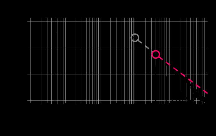
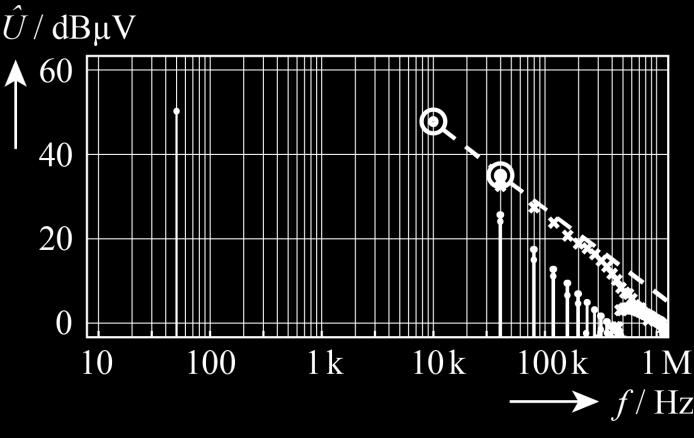
53 46/61 Multi-Airgap Inductor Core Loss Measurements (4) Total Core Loss in Sample with Varying Air Gaps and Test Fixture 500 khz Losses Increase Linearly with the Number N of Introduced Air Gaps Conclusion: Surface Layers Deteriorated by Machining of Ferrite
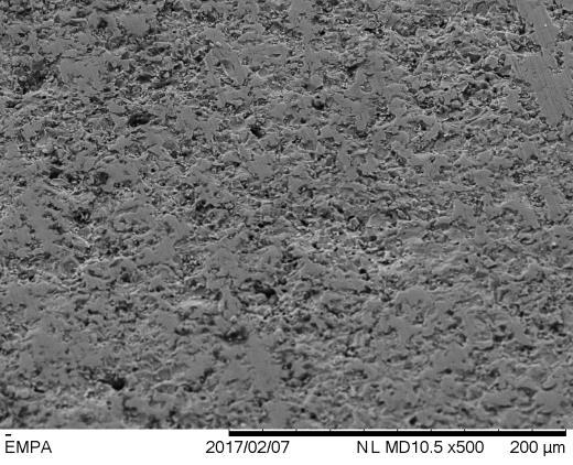
54 Analysis of Ferrite Surface Condition Untreated Samples Etched Samples Electron Microscopy Focused Ion Beam - Cut with Diamond Saw from Sintered Ferrite Rod µm Etching of Cut Plates with Hydrochloric (HCl) Acid - 45 Angle and 200 µm Resolution - FIB Preparation for 5 µm Resolution Electron Microscopy
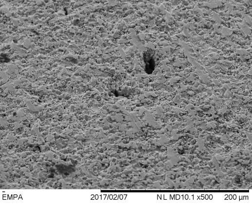
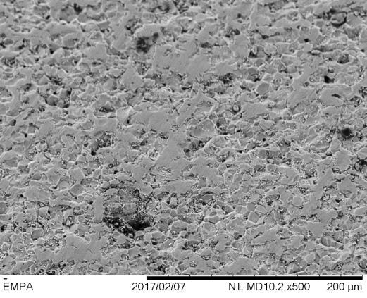
55 47/61 Comparison - Untreated Samples DMR 51 N 59 N 87
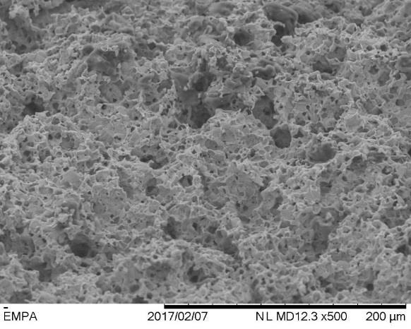
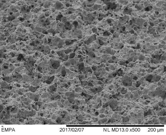
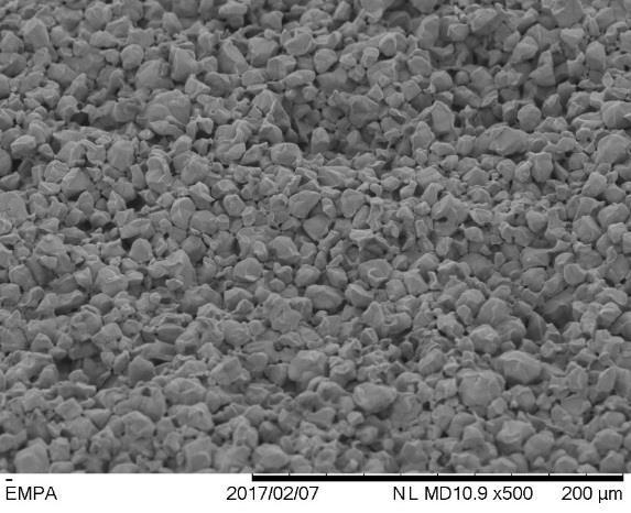
56 48/61 Comparison - Etched Samples DMR 51 N 59 N 87

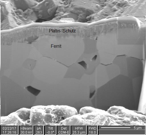
57 DMR 51 Untreated FIB Preparation (1) 49/61

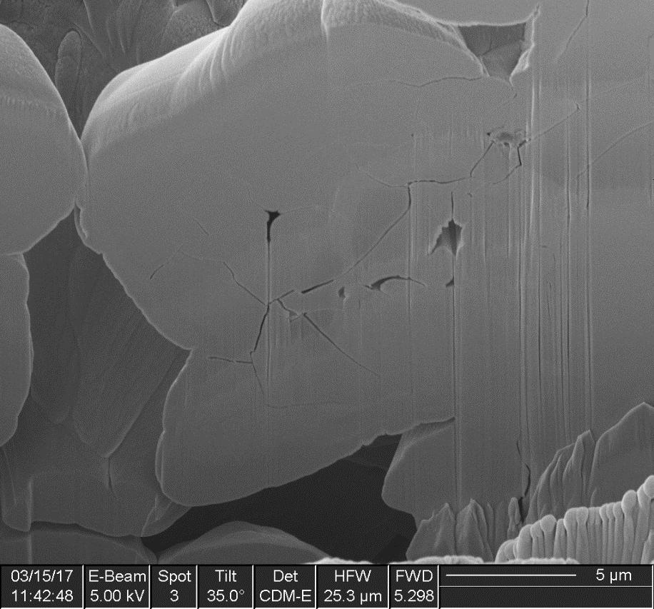
58 DMR 51 ETCHED FIB Preparation (2) 50/61
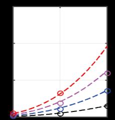
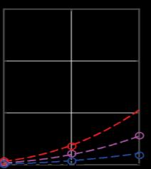


59 51/61 Multi-Airgap Inductor Core Loss Approximation (1) Solid 10 Air Gaps 20 Air Gaps DMR51 P loss (Watt) N59 P loss (Watt) N87 P loss (Watt) Comp. of Coefficients DMR51, N59, N87

 # Air Gaps # Air Gaps # Air Gaps Ext. of Steinmetz Eq.")
60 52/61 Multi-Airgap Inductor Core Loss Approximation (2) Total Core Loss in Sample with Varying Air Gaps and Test Fixture 500 khz DMR51 N59 N87 P loss (Watt) Linear Fit of Measurements Analytical Approximation of P loss (N) # Air Gaps # Air Gaps # Air Gaps Ext. of Steinmetz Eq. Sufficiently Accurate
61 53/61 Little-Box 1.0 Prototype Performance 8.2 kw/dm 3 96,3% 2kW T c =58 2kW Design Details 600V IFX Normally-Off GaN GIT Antiparallel SiC Schottky Diodes Multi-Airgap Ind. w. Multi-Layer Foil Wdg Triangular Curr. Mode ZVS Operation CeraLink Power Pulsation Buffer 135 W/in 3 Analysis of Potential Performance Improvement for Ideal Switches

62 54/61 Little-Box 1.0 Prototype Performance 8.2 kw/dm 3 96,3% 2kW T c =58 2kW Design Details 600V IFX Normally-Off GaN GIT Antiparallel SiC Schottky Diodes Multi-Airgap Ind. w. Multi-Layer Foil Wdg Triangular Curr. Mode ZVS Operation CeraLink Power Pulsation Buffer 135 W/in 3 Analysis of Potential Performance Improvement for Ideal Switches
 Step-by-Step Idealization of the Power Transistors Ideal Switches: k C = 0 (Zero Cond. Losses); k S = 0 (Zero Sw. Losses) Zero Output Cap.")
63 55/61 Little Box Ideal Switches (TCM) Multi-Objective Optimization of Little-Box 1.0 (X6S Power Pulsation Buffer) Step-by-Step Idealization of the Power Transistors Ideal Switches: k C = 0 (Zero Cond. Losses); k S = 0 (Zero Sw. Losses) Zero Output Cap. and Zero Gate Drive Losses Analysis of Improvement of Given Power Density & Maximum Power Density The Ideal Switch is NOT Enough (!)

64 56/61 Little Box Ideal Switches (PWM) ρ = 6kW/dm 3 η 99.35% L f S = 50uH = 500kHz or 900kHz L & f S are Independent Degrees of Freedom Large Design Space Diversity (Mutual Compensation of HF and LF Loss Contributions)
65 High-Efficiency 3-Φ Buck-Type PFC Rectifier

66 57/61 3-Φ Integrated Active Filter (IAF) Rectifier Injection of 3 rd Harmonic Ensures Sinusoidal Input Six-Pulse Output of Uncontrolled Rectifier Stage Buck-Type Output Stage Generates DC Output from Six-Pulse Rectifier Output Three Devices in the Main Conduction Path U in = 400V AC U O = 400V DC P O = 8kW f P = 27kHz Integrated Active Filter. 180


67 58/61 3-Φ IAF Rectifier Multi-Objective Optimization Multi-Objective Optimization - Max. Efficiency / Max. Power Density / Min. Life Cycle Costs Life Cycle Costs: (i) Initial Costs & (ii) Electricity Costs of Converter Losses 10 Years of 24/7 Operation Demands η 99% for Min. LCC

68 59/61 3-Φ IAF Rectifier Demonstrator Efficiency η > 60% Rated Load Mains Current THD I Rated Load Power Density ρ 4kW/dm 3 SiC Power MOSFETs & Diodes

69 Source: whiskeybehavior.info Overall Summary
70 60/61 Future Prospects of Power Electronics Future Extension of Power Electronics Application Area
71 61/61 Future Prospects of Magnetics Side Conditions Magnetics are Basic Functional Elements (Filtering of Sw. Frequ. Power, Transformers) Non-Ideal Material Properties (Wdg. & Core) Result in Finite Magnetics Volume (Scaling Laws) Manufacturing Limits Performance (Strand & Tape Thickness Limited Costs Option #1: Improve Modeling / Optimize Design Core Loss Modeling / Measurement Techniques (Cores and Complete Ind. / Transformer) Multi-Obj. Optimiz. Considering Full System Design for Manufacturing Option #2: Option #3: Minimize Requirement Multi-Level Converters Magnetic Integration Hybrid (Cap./Ind.) Converters Improve Material Properties / Manufacturing Integrated Cooling PCB-Based Magnetics with High Filling Factor (e.g. VICOR) Advanced Locally Adapted Litz Wire / Low-μ Material (Distributed Gap) / Low HF-Loss Material Magnetics/Passives-Centric Power Electronics Research Approach!

72 End

73 Thank You!
Power High Frequency
 Power Magnetics @ High Frequency State-of-the-Art and Future Prospects Johann W. Kolar et al. Swiss Federal Institute of Technology (ETH) Zurich Power Electronic Systems Laboratory www.pes.ee.ethz.ch Power
/ Little-Box Challenge
 1/150 / Little-Box Challenge Johann W. Kolar et al. ETH Zurich, Switzerland Power Electronic Systems Laboratory www.pes.ee.ethz.ch 2/150 / Little-Box Challenge All Team Members of ETH Zurich/FH-IZM/Fraza
VIENNA Rectifier & Beyond...
 VIENNA Rectifier & Beyond... Johann W. Kolar et al. Swiss Federal Institute of Technology (ETH) Zurich Power Electronic Systems Laboratory www.pes.ee.ethz.ch VIENNA Rectifier & Beyond... J. W. Kolar, L.
Tutorial 2 X-treme Efficiency Power Electronics
 1/114 Tutorial 2 X-treme Efficiency Power Electronics J. W. Kolar Swiss Federal Institute of Technology (ETH) Zurich Power Electronic Systems Laboratory www.pes.ee.ethz.ch 2/114 Deep Green Power Electronics
GaN in Practical Applications
 in Practical Applications 1 CCM Totem Pole PFC 2 PFC: applications and topology Typical AC/DC PSU 85-265 V AC 400V DC for industrial, medical, PFC LLC 12, 24, 48V DC telecomm and server applications. PFC
Ultra-Compact GaN- or SiC-Based Single-Phase DC/AC Power Conversion
 The Little Box Challenge Ultra-Compact GaN- or SiC-Based Single-Phase DC/AC Power Conversion J. W. Kolar, D. Neumayr, D. Bortis Swiss Federal Institute of Technology (ETH) Zurich Power Electronic Systems
Power Electronics Design 4.0
 IEEE Design Automation for Power Electronics Workshop Power Electronics Design 4.0 Johann W. Kolar Swiss Federal Institute of Technology (ETH) Zurich Power Electronic Systems Laboratory www.pes.ee.ethz.ch
In Search of Powerful Circuits: Developments in Very High Frequency Power Conversion
 Massachusetts Institute of Technology Laboratory for Electromagnetic and Electronic Systems In Search of Powerful Circuits: Developments in Very High Frequency Power Conversion David J. Perreault Princeton
Power Electronics 2.0 Johann W. Kolar
 Power Electronics 2.0 Johann W. Kolar Swiss Federal Institute of Technology (ETH) Zurich Power Electronic Systems Laboratory www.pes.ee.ethz.ch Outline Evolution of Power Electronics Performance Trends
Cree PV Inverter Tops 1kW/kg with All-SiC Design
 Cree PV Inverter Tops 1kW/kg with All-SiC Design Alejandro Esquivel September, 2014 Power Forum 2014 (Bologna) presentation sponsored by: Presentation Outline 1. Meeting an Industry Need a) 1kW/Kg b) No
Conceptualization and Multi-Objective Optimization of the Electric System of an Airborne Wind Turbine
 1/81 1/82 Conceptualization and Multi-Objective Optimization of the Electric System of an Airborne Wind Turbine J. W. Kolar et al. Swiss Federal Institute of Technology (ETH) Zurich Power Electronic Systems
Miniaturized High-Frequency Integrated Power Conversion for Grid Interface
 Massachusetts Institute of Technology Laboratory for Electromagnetic and Electronic Systems Miniaturized High-Frequency Integrated Power Conversion for Grid Interface David J. Perreault Seungbum Lim David
Welcome. High Efficiency SMPS with Digital Loop Control
 Welcome High Efficiency SMPS with Digital Loop Control Presenter: Walter Mosa Company: MagneTek IBM Power and Cooling Technology Symposium September 20-21st FE 1U 800-12 High Density AC/DC Front-End Design
Improvements of LLC Resonant Converter
 Chapter 5 Improvements of LLC Resonant Converter From previous chapter, the characteristic and design of LLC resonant converter were discussed. In this chapter, two improvements for LLC resonant converter
Medium Frequency Transformers for Solid-State-Transformer Applications - Design and Experimental Verification
 IEEE Proceedings of the th IEEE International Conference on Power Electronics and Drive Systems (PEDS ), Kitakyushu, Japan, April -, Medium Frequency Transformers for Solid-State-Transformer Applications
Advanced Silicon Devices Applications and Technology Trends
 Advanced Silicon Devices Applications and Technology Trends Gerald Deboy Winfried Kaindl, Uwe Kirchner, Matteo Kutschak, Eric Persson, Michael Treu APEC 2015 Content Silicon devices versus GaN devices:
SIMULATION STUDIES OF HALF-BRIDGE ISOLATED DC/DC BOOST CONVERTER
 POZNAN UNIVE RSITY OF TE CHNOLOGY ACADE MIC JOURNALS No 80 Electrical Engineering 2014 Adam KRUPA* SIMULATION STUDIES OF HALF-BRIDGE ISOLATED DC/DC BOOST CONVERTER In order to utilize energy from low voltage
800 W PFC evaluation board
 800 W PFC evaluation board EVAL_800W_PFC_C7_V2 / SP001647120 / SA001647124 High power density 800 W 130 khz platinum server design with analog & digital control Garcia Rafael (IFAT PMM ACDC AE) Zechner
Vision Power Electronics 2025
 1/102 Vision Power Electronics 2025 Johann W. Kolar Swiss Federal Institute of Technology (ETH) Zurich Power Electronic Systems Laboratory www.pes.ee.ethz.ch 2/102 Power Electronics 2.0 Johann W. Kolar
CONTENTS 2/ /7 8/9 10/11 12/13 14/15 16/17 18/19 20/21 22/23 24/25 26/27 28/29 30/31 32/ Contact Us 38
 CONTENTS Market Sectors Company Profile Planar Technology Product Range Overview Size 10 MAX 1kW Size 195 MAX 1.5kW Size 225 MAX 2kW Size 20 MAX 2kW Size 50 MAX 6.5kW Size 500 MAX 10kW Size 510 MAX 10kW
Exploring the Pareto Front of Multi-Objective Single-Phase PFC Rectifier Design Optimization % Efficiency vs. 7kW/dm 3 Power Density
 Exploring the Pareto Front of Multi-Objective Single-Phase PFC Rectifier Design Optimization - 99.% Efficiency vs. 7kW/dm 3 Power Density J. W. Kolar, J. Biela and J. Miniböck ETH Zurich, Power Electronic
A Highly Versatile Laboratory Setup for Teaching Basics of Power Electronics in Industry Related Form
 A Highly Versatile Laboratory Setup for Teaching Basics of Power Electronics in Industry Related Form JOHANN MINIBÖCK power electronics consultant Purgstall 5 A-3752 Walkenstein AUSTRIA Phone: +43-2913-411
Impact of Power Density Maximization on Efficiency of DC DC Converter Systems
 Impact of Power Density Maximization on Efficiency of DC DC Converter Systems Juergen Biela, Member, IEEE, Uwe Badstuebner, Student Member, IEEE, and JohannW. Kolar, Senior Member, IEEE This material is
IBM Technology Symposium
 IBM Technology Symposium Impact of Input Voltage on Server PSU- Efficiency, Power Density and Cost Design. Build. Ship. Service. Sriram Chandrasekaran November 13, 2012 Presentation Outline Redundant Server
DC-DC Converter for Gate Power Supplies with an Optimal Air Transformer
 DC-DC Converter for Gate Power Supplies with an Optimal Air Transformer Christoph Marxgut*, Jürgen Biela*, Johann W. Kolar*, Reto Steiner and Peter K. Steimer _Power Electronic Systems Laboratory, ETH
2.8 Gen4 Medium Voltage SST Development
 2.8 Gen4 Medium Voltage SST Development Project Number Year 10 Projects and Participants Project Title Participants Institution Y10ET3 Gen4 Medium Voltage SST Development Yu, Husain NCSU 2.8.1 Intellectual
25 Watt DC/DC converter using integrated Planar Magnetics
 technical note 25 Watt DC/DC converter using integrated Planar Magnetics Philips Components 25 Watt DC/DC converter using integrated Planar Magnetics Contents Introduction 2 Converter description 3 Converter
MegaCube. G. Ortiz, J. Biela, J.W. Kolar. Swiss Federal Institute of Technology (ETH) Zurich Power Electronic Systems Laboratory
 Zurich Power Electronic Systems Laboratory") MegaCube G. Ortiz, J. Biela, J.W. Kolar Swiss Federal Institute of Technology (ETH) Zurich Power Electronic Systems Laboratory www.pes.ee.ethz.ch Offshore Wind Power Generation: DC v/s AC Transmission
MegaCube G. Ortiz, J. Biela, J.W. Kolar Swiss Federal Institute of Technology (ETH) Zurich Power Electronic Systems Laboratory www.pes.ee.ethz.ch Offshore Wind Power Generation: DC v/s AC Transmission
Dielectric Losses: MV/MF Converter Insulation
 Research Collection Other Conference Item Dielectric Losses: MV/MF Converter Insulation Author(s): Guillod, Thomas; Krismer, Florian; Kolar, Johann W. Publication Date: 2017 Permanent Link: https://doi.org/10.3929/ethz-b-000225431
Power of GaN. Enabling designers to create smaller, more efficient and higher-performing AC/DC power supplies
 Power of GaN Enabling designers to create smaller, more efficient and higher-performing AC/DC power supplies Steve Tom Product Line Manager, GaN Products stom@ti.com Solving power and energy-management
The Quest for High Power Density
 The Quest for High Power Density Welcome to the GaN Era Power Conversion Technology Drivers Key design objectives across all applications: High power density High efficiency High reliability Low cost 2
Recent Approaches to Develop High Frequency Power Converters
 The 1 st Symposium on SPC (S 2 PC) 17/1/214 Recent Approaches to Develop High Frequency Power Converters Location Fireworks Much snow Tokyo Nagaoka University of Technology, Japan Prof. Jun-ichi Itoh Dr.
Gallium nitride technology in server and telecom applications
 White Paper Gallium nitride technology in server and telecom applications The promise of GaN in light of future requirements for power electronics Abstract This paper will discuss the benefits of e-mode
Design and Experimental Analysis of a Medium-Frequency Transformer for Solid-State Transformer Applications
 2017 IEEE IEEE Journal of Emerging and Selected Topics in Power Electronics, Vol. 5, No. 1, pp. 110-123, March 2017 Design and Experimental Analysis of a Medium-Frequency Transformer for Solid-State Transformer
Impact of the Flying Capacitor on the Boost converter
 mpact of the Flying Capacitor on the Boost converter Diego Serrano, Víctor Cordón, Miroslav Vasić, Pedro Alou, Jesús A. Oliver, José A. Cobos Universidad Politécnica de Madrid, Centro de Electrónica ndustrial
Fundamentals of Power Electronics
 Fundamentals of Power Electronics SECOND EDITION Robert W. Erickson Dragan Maksimovic University of Colorado Boulder, Colorado Preface 1 Introduction 1 1.1 Introduction to Power Processing 1 1.2 Several
R. W. Erickson. Department of Electrical, Computer, and Energy Engineering University of Colorado, Boulder
 R. W. Erickson Department of Electrical, Computer, and Energy Engineering University of Colorado, Boulder 13.2.3 Leakage inductances + v 1 (t) i 1 (t) Φ l1 Φ M Φ l2 i 2 (t) + v 2 (t) Φ l1 Φ l2 i 1 (t)
Optimization of Full Bridge topology with triangular current for avionic applications
 Proyecto Fin de Máster Optimization of Full Bridge topology with triangular current for avionic applications Yann Emmanuel Bouvier Rescalvo Máster en Electrónica Industrial Universidad Politécnica de Madrid
Designing High density Power Solutions with GaN Created by: Masoud Beheshti Presented by: Xaver Arbinger
 Designing High density Power Solutions with GaN Created by: Masoud Beheshti Presented by: Xaver Arbinger Topics Why GaN? Integration for Higher System Performance Application Examples Taking GaN beyond
The First Step to Success Selecting the Optimal Topology Brian King
 The First Step to Success Selecting the Optimal Topology Brian King 1 What will I get out of this session? Purpose: Inside the Box: General Characteristics of Common Topologies Outside the Box: Unique
Achieving High Power Density Designs in DC-DC Converters
 Achieving High Power Density Designs in DC-DC Converters Agenda Marketing / Product Requirement Design Decision Making Translating Requirements to Specifications Passive Losses Active Losses Layout / Thermal
Gallium nitride technology in adapter and charger applications
 White Paper Gallium nitride technology in adapter and charger applications The promise of GaN in light of future requirements for power electronics Abstract This paper will discuss the benefits of e-mode
Optimal Design of a 3.5 kv/11kw DC-DC Converter for Charging Capacitor Banks of Power Modulators
 Optimal Design of a 3.5 kv/11kw DC-DC Converter for Charging Capacitor Banks of Power Modulators G. Ortiz, D. Bortis, J. Biela and J. W. Kolar Power Electronic Systems Laboratory, ETH Zurich Email: ortiz@lem.ee.ethz.ch
ThinPAK 8x8. New High Voltage SMD-Package. April 2010 Version 1.0
 ThinPAK 8x8 New High Voltage SMD-Package Version 1.0 Content Introduction Package Specification Thermal Concept Application Test Conditions Impact on Efficiency and EMI Switching behaviour Portfolio and
Challenges and Trends in Magnetics
 Challenges and Trends in Magnetics Prof. W. G. Hurley Power Electronics Research Centre National University of Ireland, Galway IEEE Distinguished Lecture The University of Hong Kong 27 May 2016 Outline
AT7450 2A-60V LED Step-Down Converter
 FEATURES DESCRIPTION IN Max = 60 FB = 200m Frequency 52kHz I LED Max 2A On/Off input may be used for the Analog Dimming Thermal protection Cycle-by-cycle current limit I LOAD max =2A OUT from 0.2 to 55
Conventional Single-Switch Forward Converter Design
 Maxim > Design Support > Technical Documents > Application Notes > Amplifier and Comparator Circuits > APP 3983 Maxim > Design Support > Technical Documents > Application Notes > Power-Supply Circuits
IN A CONTINUING effort to decrease power consumption
 184 IEEE TRANSACTIONS ON POWER ELECTRONICS, VOL. 14, NO. 1, JANUARY 1999 Forward-Flyback Converter with Current-Doubler Rectifier: Analysis, Design, and Evaluation Results Laszlo Huber, Member, IEEE, and
10kW Three-phase SiC PFC Rectifier
 www.onsemi.com 10kW Three-phase SiC PFC Rectifier SEMICON EUROPA, Nov 13-18, 2018, Munich, Germany Contents General PFC Concept 3 Phase System and PFC Control Simulation Understanding the losses 3 Phase
Experimental Verification of the Efficiency/Power-Density (n-p) Pareto Front of Single-Phase Double- Boost and TCM PFC Rectifier Systems
 Pareto Front of Single-Phase Double- Boost and TCM PFC Rectifier Systems") 213 IEEE Proceedings of the 28th Applied Power Electronics Conference and Exposition (APEC 213), Long Beach, California, USA, March 17-21, 213 Experimental Verification of the Efficiency/Power-Density
213 IEEE Proceedings of the 28th Applied Power Electronics Conference and Exposition (APEC 213), Long Beach, California, USA, March 17-21, 213 Experimental Verification of the Efficiency/Power-Density
Design considerations for a Half- Bridge LLC resonant converter
 Design considerations for a Half- Bridge LLC resonant converter Why an HB LLC converter Agenda Configurations of the HB LLC converter and a resonant tank Operating states of the HB LLC HB LLC converter
How to Design Multi-kW Converters for Electric Vehicles
 How to Design Multi-kW Converters for Electric Vehicles Part 1: Part 2: Part 3: Part 4: Part 5: Part 6: Part 7: Part 8: Electric Vehicle power systems Introduction to Battery Charging Power Factor and
Pitch Pack Microsemi full SiC Power Modules
 Pitch Pack Microsemi full SiC Power Modules October 2014 SiC Main Characteristics vs. Si Characteristics SiC vs. Si Results Benefits Breakdown field (MV/cm) Electron sat. velocity (cm/s) Bandgap energy
Solid State Pulse Modulators - Basic Concepts and Examples - Jürgen Biela S. Blume, M. Jaritz, G. Tsolaridis
 Solid State Pulse Modulators - Basic Concepts and Examples - Jürgen Biela S. Blume, M. Jaritz, G. Tsolaridis 1 Energy related Research @ D-ITET / ETH Zurich Professorship in HIGH POWER ELECTRONICS Start
Boundary Mode Offline LED Driver Using MP4000. Application Note
 The Future of Analog IC Technology AN046 Boundary Mode Offline LED Driver Using MP4000 Boundary Mode Offline LED Driver Using MP4000 Application Note Prepared by Zheng Luo March 25, 2011 AN046 Rev. 1.0
Designing reliable and high density power solutions with GaN. Created by: Masoud Beheshti Presented by: Paul L Brohlin
 Designing reliable and high density power solutions with GaN Created by: Masoud Beheshti Presented by: Paul L Brohlin What will I get out of this presentation? Why GaN? Integration for System Performance
TRENCHSTOP 5 boosts efficiency in Home Appliance, Solar and Welding Applications
 TRENCHSTOP 5 boosts efficiency in Home Appliance, Solar and Welding Applications Davide Chiola - Senior Mgr IGBT Application Engineering Mark Thomas Product Marketing Mgr Discrete IGBT Infineon Technologies
Unlocking the Power of GaN PSMA Semiconductor Committee Industry Session
 Unlocking the Power of GaN PSMA Semiconductor Committee Industry Session March 24 th 2016 Dan Kinzer, COO/CTO dan.kinzer@navitassemi.com 1 Mobility (cm 2 /Vs) EBR Field (MV/cm) GaN vs. Si WBG GaN material
Using the Latest Wolfspeed C3M TM SiC MOSFETs to Simplify Design for Level 3 DC Fast Chargers
 Using the Latest Wolfspeed C3M TM SiC MOSFETs to Simplify Design for Level 3 DC Fast Chargers Abstract This paper will examine the DC fast charger market and the products currently used in that market.
Digital Control IC for Interleaved PFCs
 Digital Control IC for Interleaved PFCs Rosario Attanasio Applications Manager STMicroelectronics Presentation Outline 2 PFC Basics Interleaved PFC Concept Analog Vs Digital Control The STNRGPF01 Digital
High Performance ZVS Buck Regulator Removes Barriers To Increased Power Throughput In Wide Input Range Point-Of-Load Applications
 WHITE PAPER High Performance ZVS Buck Regulator Removes Barriers To Increased Power Throughput In Wide Input Range Point-Of-Load Applications Written by: C. R. Swartz Principal Engineer, Picor Semiconductor
Practical Considerations in the Design of Power Converters. Prof. Sujit K. Biswas Dept. of Electrical Engg. Jadavpur University Kolkata , INDIA
 Practical Considerations in the Design of Power Converters Prof. Sujit K. Biswas Dept. of Electrical Engg. Jadavpur University Kolkata 700032, INDIA 1 Power Electronics can be considered as : The technology
Australian Journal of Basic and Applied Sciences. Design of a Half Bridge AC AC Series Resonant Converter for Domestic Application
 ISSN:1991-8178 Australian Journal of Basic and Applied Sciences Journal home page: www.ajbasweb.com Design of a Half Bridge AC AC Series Resonant Converter for Domestic Application K. Prabu and A.Ruby
West Coast Magnetics. Advancing Power Electronics FOIL WINDINGS FOR SMPS INDUCTORS AND TRANSFORMERS. Weyman Lundquist, CEO and Engineering Manager
 1 West Coast Magnetics Advancing Power Electronics FOIL WINDINGS FOR SMPS INDUCTORS AND TRANSFORMERS Weyman Lundquist, CEO and Engineering Manager TYPES OF WINDINGS 2 Solid wire Lowest cost Low DC resistance
Performance Evaluation of GaN based PFC Boost Rectifiers
 Performance Evaluation of GaN based PFC Boost Rectifiers Srinivas Harshal, Vijit Dubey Abstract - The power electronics industry is slowly moving towards wideband semiconductor devices such as SiC and
Frequency, where we are today, and where we need to go
 Frequency, where we are today, and where we need to go Ionel Dan Jitaru Rompower Energy Systems Inc. 6262 N. Swan Rd., Suite 200 Tucson, Arizona 85718 OUTLINE Directions in topologies and operation frequency
HIGH FREQUENCY CLASS DE CONVERTER USING A MULTILAYER CORELESS PCB TRANSFORMER
 HIGH FREQUENCY CLASS DE CONVERTER USING A MULTILAYER CORELESS PCB TRANSFORMER By Somayeh Abnavi A thesis submitted to the Department of Electrical and Computer Engineering In conformity with the requirements
High-Power-Density 400VDC-19VDC LLC Solution with GaN HEMTs
 High-Power-Density 400VDC-19VDC LLC Solution with GaN HEMTs Yajie Qiu, Lucas (Juncheng) Lu GaN Systems Inc., Ottawa, Canada yqiu@gansystems.com Abstract Compared to Silicon MOSFETs, GaN Highelectron-Mobility
Designing a 99% Efficient Totem Pole PFC with GaN. Serkan Dusmez, Systems and applications engineer
 Designing a 99% Efficient Totem Pole PFC with GaN Serkan Dusmez, Systems and applications engineer 1 What will I get out of this session? Purpose: Why GaN Based Totem-pole PFC? Design guidelines for getting
6.334 Final Project Buck Converter
 Nathan Monroe monroe@mit.edu 4/6/13 6.334 Final Project Buck Converter Design Input Filter Filter Capacitor - 40µF x 0µF Capstick CS6 film capacitors in parallel Filter Inductor - 10.08µH RM10/I-3F3-A630
CHAPTER 2 EQUIVALENT CIRCUIT MODELING OF CONDUCTED EMI BASED ON NOISE SOURCES AND IMPEDANCES
 29 CHAPTER 2 EQUIVALENT CIRCUIT MODELING OF CONDUCTED EMI BASED ON NOISE SOURCES AND IMPEDANCES A simple equivalent circuit modeling approach to describe Conducted EMI coupling system for the SPC is described
Smart (Solid-State) Transformers Concepts/Challenges/Applications
 Transformers Concepts/Challenges/Applications") Smart (Solid-State) Transformers Concepts/Challenges/Applications J. W. Kolar et al. Swiss Federal Institute of Technology (ETH) Zurich Power Electronic Systems Laboratory www.pes.ee.ethz.ch Smart (Solid-State)
Smart (Solid-State) Transformers Concepts/Challenges/Applications J. W. Kolar et al. Swiss Federal Institute of Technology (ETH) Zurich Power Electronic Systems Laboratory www.pes.ee.ethz.ch Smart (Solid-State)
3A Step-Down Voltage Regulator
 3A Step-Down Voltage Regulator DESCRIPITION The is monolithic integrated circuit that provides all the active functions for a step-down(buck) switching regulator, capable of driving 3A load with excellent
12-Pulse Rectifier for More Electric Aircraft Applications
 12-Pulse Rectifier for More Electric Aircraft Applications G. Gong, U. Drofenik and J.W. Kolar ETH Zurich, Power Electronic Systems Laboratory ETH Zentrum / ETL H23, Physikstr. 3, CH-892 Zurich / SWITZERLAND
A High Efficient Integrated Planar Transformer for Primary-Parallel Isolated Boost Converters
 A High Efficient Integrated Planar Transformer for Primary-Parallel Isolated Boost Converters Gokhan Sen 1, Ziwei Ouyang 1, Ole C. Thomsen 1, Michael A. E. Andersen 1, and Lars Møller 2 1. Department of
Converters Theme Andrew Forsyth
 Converters Theme Andrew Forsyth The University of Manchester Overview Research team Vision, objectives and organisation Update on technical activities / achievements Topologies Structural and functional
Chapter 6 Soft-Switching dc-dc Converters Outlines
 Chapter 6 Soft-Switching dc-dc Converters Outlines Classification of soft-switching resonant converters Advantages and disadvantages of ZCS and ZVS Zero-current switching topologies The resonant switch
Efficiency Improvement of High Frequency Inverter for Wireless Power Transfer System Using a Series Reactive Power Compensator
 IEEE PEDS 27, Honolulu, USA 2-5 December 27 Efficiency Improvement of High Frequency Inverter for Wireless Power Transfer System Using a Series Reactive Power Compensator Jun Osawa Graduate School of Pure
Impact of Fringing Effects on the Design of DC-DC Converters
 Impact of Fringing Effects on the Design of DC-DC Converters Michael Seeman, Ph.D. Founder / CEO. 2018 APEC PSMA/PELS 2018. Outline Fringe-field loss: What does a power supply designer need to know? Which
A new compact power modules range for efficient solar inverters
 A new compact power modules range for efficient solar inverters Serge Bontemps, Pierre-Laurent Doumergue Microsemi PPG power module Products, Chemin de Magret, F-33700 Merignac Abstract The decrease of
1. The current-doubler rectifier can be used to double the load capability of isolated dc dc converters with bipolar secondaryside
 Highlights of the Chapter 4 1. The current-doubler rectifier can be used to double the load capability of isolated dc dc converters with bipolar secondaryside voltage. Some industry-generated papers recommend
DIO6305 High-Efficiency 1.2MHz, 1.1A Synchronous Step-Up Converter
 High-Efficiency 1.2MHz, 1.1A Synchronous Step-Up Converter Rev 1.2 Features High-Efficiency Synchronous-Mode 2.7-5.25V input voltage range Device Quiescent Current: 30µA (TYP) Less than 1µA Shutdown Current
CHAPTER 2 GENERAL STUDY OF INTEGRATED SINGLE-STAGE POWER FACTOR CORRECTION CONVERTERS
 CHAPTER 2 GENERAL STUDY OF INTEGRATED SINGLE-STAGE POWER FACTOR CORRECTION CONVERTERS 2.1 Introduction Conventional diode rectifiers have rich input harmonic current and cannot meet the IEC PFC regulation,
Power Matters Microsemi SiC Products
 Microsemi SiC Products James Kerr Director of Marketing Power Discrete Products Microsemi Power Products MOSFETs (100V-1200V) Highest Performance SiC MOSFETs 1200V MOSFETs FREDFETs (MOSFET with fast body
Get Your GaN PhD in Less Than 60 Minutes!
 Get Your GaN PhD in Less Than 60 Minutes! 1 Detailed agenda Why is GaN Exciting GaN Fundamentals Cost and Reliability Totem Pole PFC Isolated LLC Motor Drive LiDAR Driving GaN Choosing a GaN Tools 4 Why
Single-Loop Control of Buck Power-Pulsation Buffer for AC-DC Converter System
 Single-Loop Control of Buck Power-Pulsation Buffer for AC-DC Converter System Yuri Panov, Milan M. Jovanovi, and Brian T. Irving Power Electronics Laboratory Delta Products Corporation 5101 Davis Drive,
Ultra Compact Three-phase PWM Rectifier
 Ultra Compact Three-phase PWM Rectifier P. Karutz, S.D. Round, M.L. Heldwein and J.W. Kolar Power Electronic Systems Laboratory ETH Zurich Zurich, 8092 SWITZERLAND karutz@lem.ee.ethz.ch Abstract An increasing
Design of step-up converter for a constant output in a high power design
 2015; 1(6): 125-129 ISSN Print: 2394-7500 ISSN Online: 2394-5869 Impact Factor: 3.4 IJAR 2015; 1(6): 125-129 www.allresearchjournal.com Received: 25-03-2015 Accepted: 27-04-2015 M. Tech, (VLSI Design and
Two-output Class E Isolated dc-dc Converter at 5 MHz Switching Frequency 1 Z. Pavlović, J.A. Oliver, P. Alou, O. Garcia, R.Prieto, J.A.
 Two-output Class E Isolated dc-dc Converter at 5 MHz Switching Frequency 1 Z. Pavlović, J.A. Oliver, P. Alou, O. Garcia, R.Prieto, J.A. Cobos Universidad Politécnica de Madrid Centro de Electrónica Industrial
Gate drive card converts logic level turn on/off commands. Gate Drive Card for High Power Three Phase PWM Converters. Engineer R&D
 Gate Drive Card for High Power Three Phase PWM Converters 1 Anil Kumar Adapa Engineer R&D Medha Servo Drive Pvt. Ltd., India Email: anilkumaradapa@gmail.com Vinod John Department of Electrical Engineering
AT2596 3A Step Down Voltage Switching Regulators
 FEATURES Standard PSOP-8/TO-220-5L /TO-263-5L Package Adjustable Output Versions Adjustable Version Output Voltage Range 1.23V to 37V V OUT Accuracy is to ± 3% Under Specified Input Voltage the Output
2017 IEEE. IEEE Transactions on Power Electronics, Vol. 32, No. 10, pp , October M. Kasper, D. Bortis, G. Deboy, J. W.
 2017 IEEE IEEE Transactions on Power Electronics, Vol. 32, No. 10, pp. 7750-7769, October 2017 Design of a Highly Efficient (97.7%) and Very Compact (2.2 kw/dm3) Isolated AC DC Telecom Power Supply Module
Comparison and Design of High Efficiency Microinverters for Photovoltaic Applications
 Comparison and Design of High Efficiency Microinverters for Photovoltaic Applications Jason C. Dominic Thesis submitted to the faculty of the Virginia Polytechnic Institute and State University in partial
High Efficiency Flyback Converter Technology
 High Efficiency Flyback Converter Technology U. Boeke ulrich.boeke@philips.com Philips Research Laboratories Aachen, Germany Abstract - Technologies are discussed to realize a DC/DC Flyback converter with
ELEC387 Power electronics
 ELEC387 Power electronics Jonathan Goldwasser 1 Power electronics systems pp.3 15 Main task: process and control flow of electric energy by supplying voltage and current in a form that is optimally suited
Voltage Fed DC-DC Converters with Voltage Doubler
 Chapter 3 Voltage Fed DC-DC Converters with Voltage Doubler 3.1 INTRODUCTION The primary objective of the research pursuit is to propose and implement a suitable topology for fuel cell application. The
A new era in power electronics with Infineon s CoolGaN
 A new era in power electronics with Infineon s CoolGaN Dr. Gerald Deboy Senior Principal Power Discretes and System Engineering Power management and multimarket division Infineon will complement each of
Sensitivity of Telecom DC-DC Converter Optimization to the Level of Detail of the System Model
 11 IEEE Proceedings of the 26th nnual IEEE pplied Power Electronics onference and Exposition (PE 11), Ft. Worth, TX, US, March 6 10, 11. Sensitivity of Telecom D-D onverter Optimization to the Level of
Research Challenges and Future Perspectives of Solid-State Transformers
 1/90 1/150 Research Challenges and Future Perspectives of Solid-State Transformers J. W. Kolar et al. Swiss Federal Institute of Technology (ETH) Zurich Power Electronic Systems Laboratory www.pes.ee.ethz.ch
IN THE high power isolated dc/dc applications, full bridge
 354 IEEE TRANSACTIONS ON POWER ELECTRONICS, VOL. 21, NO. 2, MARCH 2006 A Novel Zero-Current-Transition Full Bridge DC/DC Converter Junming Zhang, Xiaogao Xie, Xinke Wu, Guoliang Wu, and Zhaoming Qian,