What is EMC/EMI. EMS (Immunity) RE RE
|
|
|
- Ariel McKinney
- 5 years ago
- Views:
Transcription

1 Entrance to EMI
 Emission CS(RS) : Conducted(Radiated) Susceptibility CM : Common-Mode Component DM : Differential-Mode Component CE RE CS RS RE CM DM CE EUT(DUT) EMC has verified / classified by")
2 What is EMC/EMI Classification of EMC EMC (Electro-Magnetic Compatibility) EMI (Emission) EMS (Immunity) EMI : Electro-Magnetic Interference EMS : Electro-Magnetic Susceptibility CE(RE) : Conducted(Radiated) Emission CS(RS) : Conducted(Radiated) Susceptibility CM : Common-Mode Component DM : Differential-Mode Component CE RE CS RS RE CM DM CE EUT(DUT) EMC has verified / classified by its characteristics and the co-relation with EUT This presentation is concentrated on CE of EMI, especially for CM and DM in CE EUT(DUT) = Equipment Under Test (Device Under Test)
3 What is EMI Classification of EMI Acoustic Noise Conducted RF Disturbance (CE) Power Disturbance 16Hz 60Hz 2.4KHz 20KHz 150KHz 30MHz 300MHz 1GHz Sub Harmonics Harmonics 9KHz Lighting device Radiated Disturbance (RE) The Classification of EMC is done by frequency range The range is being changed by introducing new EUT, day by day World-wide and/or each country has the regulation/standard of EMC/EMI related and any of EUT has controlled by such regulation/standard Mostly familiar regulation/standard are CISPR(The International Special Committee On Radio Interference) EN (European Norm) FCC (Federal Communications Commission) IEC (International Electrotechnical Commission)
 300MHz CM : Common-Mode Noise = Noise Line to Ground DM : Differential-Mode Noise = Noise Line to Line CM Noise Line Neutral Ground DM Noise CM")
4 EMI (Emission) What CE and CM / DM CE RE CE Power In Power Out CM DM EUT Conducted Disturbance (CE) 9KHz 150KHz 30MHz 1.1GHz CE -- Noise moved through the line(s) to EUT???? Radiated Disturbance (RE) 300MHz CM : Common-Mode Noise = Noise Line to Ground DM : Differential-Mode Noise = Noise Line to Line CM Noise Line Neutral Ground DM Noise CM Noise DM Noise
5 Measurement of the Noise(s) EMI Receiver LISN Measurement is done by EMI Receiver Occasionally done by Spectrum Analyzer, but not recommended Basic equipment are EMI receiver and LISN(Line Impedance Stabilization Network) Configuration and Setup of Measurement equipment be decided / done by -- what kind of EUT to be measured -- which regulation/standard is applied LISN has various models, according to the power condition(of EUT), like 16A to 200A, 1ph to 3ph Measurement is recommended to select/choose a place, having minimized outer noise influence, like in chamber or mini-shield room.
")


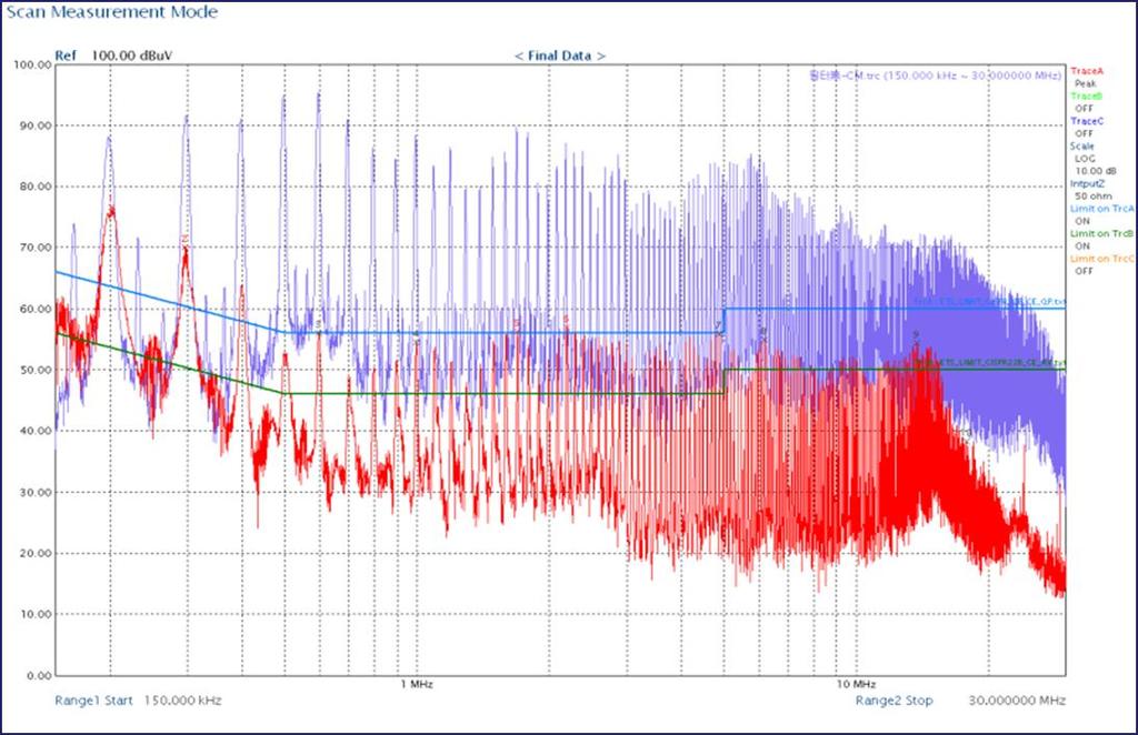
6 Measurement of the Noise(s) EMI Receiver LISN EUT Measured results Total Noise = CM + DM Differential-Mode(DM) Common-Mode(CM)


, two limit lines are used, Quasi-Peak and Average In")
7 What is EMI Debugging Debugging Process Over the Limit Line (total noise) Solved = Debugged Solution = Debugging is to reduce/control the noise under the limit lines. Magnitude (dbμv) Limit Lines Peak Quasi-Peak Average Peak < Quasi-Peak < Average Frequency Between 150KHz to 30MHz, Peak is always the highest level Level & Shape of Limit Lines are determined by the regulation/standard, applied on EUT There are 3 types of Limit Lines ; Peak, Quasi-Peak, and Average In Certification/Approval (from lab), two limit lines are used, Quasi-Peak and Average In debugging, Peak limit line is used.
8 How to Reduce the Noise(s) What is EMI Debugging Various way of methods can be considered/applied to reduce the noise(s) Below are some of mostly used method/consideration Recommended the Filter should be the LAST solution Pattern The Ideal approach To achieve most recommended EMI Solution/Debugging, EMI consideration/design should be started at the same time of EUT design Wiring Do not do the wire twisted Allocate wires be separated, as far as possible Actual in the field = EMI Solution/Debugging is the last, after EUT design is finished Position Filter should be located at the just entrance of power input Shielding Power Input EMI Filter EUT Shield any components, causing noises, Separate the components with shielding materials Filters : The Last & Final Solution = Debugging


9 What is EMI Debugging Why EMI Debugging is Difficult - Filter Design Measured Noise = Total Noise = CM + DM Filter is consisted with two types of components Common-Mode Group -- CM Coil and Y-Capacitor Differential-Mode Group -- DM Coil and X-Capacitor
10 What is EMI Debugging Why EMI Debugging is Difficult - Filter Design How to determine the noise is CM or DM, from the measured noise, total noise??? Experience Know-How How to select the components??? Know-How Experience How fast the components selection can be done??? Experience Know-How How to be sure the selected components are accurate & exact size for the solution??? Know-How Experience
11 What is EMI Debugging Summary of EMI Solution = Debugging = EMI Filter Design Analysis and Measurement of Exact Noise by mode, CM and DM EMI Solution = Debugging is finalized by EMI Filter (EMI Filter Design) Understanding more and more about the components being used on EMI Filter Design EMI Filter, using smaller Components and less Quantity Successful EMI Debugging = Good & Fast Filter Design COST SAVING = COMPETITIVENESS
12 Solution - EMCIS Consideration to make EMI Debugging as EASY WORK MEASURE the noises by mode, CM and DM, respectively SELECT the components in exact size and performance, mode by mode SIMULATE the performance of the components and the filter APPLY the selected components as Primary filter to EUT
 Measure each of noises, CM and DM,")

13 EMCIS Solution ; EA-2100 Solution - EMCIS EMI Analyzer (EA-2100) Measure each of noises, CM and DM, respectively Select Components per each Mode, CM and DM, one by one Apply selected components as Primary filter to EUT


14 EMCIS Solution ; EA-300 Solution - EMCIS EMI Analyzer (EA-300) Measure each of noises, CM and DM, respectively Select Components per each Mode, CM and DM, one by one Simulate the performance of the selected components and also the designed filter Apply selected components as Primary filter to EUT

 Available to")

 FTK-05 Packaged System with")
15 Basic System Configuration EA-2100 Solution - EMCIS Basic System consist of EMI Receiver, EMI Analyzer(EA-2100), and LISN EA-2100 consists of main body and Filter Test Kit(FTK-05) Available to supply the item in individual unit and also as package Mini Shield Room should be a good option for effective and economical test environment EMI Analyzer (EA-2100) FTK-05 Packaged System with Mini Shield Room


16 Debugging Do It Yourself Preparation System Set Up Set up the system = EMI Receiver + EA FTK-05 + LISN Set up EMI Receiver as your selected measurement condition Most EMI Receiver has EMI software which set up the limit lines, frequency ranges, and etc, by only selecting the regulation/standard, like CISPR14.. System Configuration EMI Receiver EA-2100 Power Line Filter LISN DM FTK-05 CM CM EUT Check the ground of each unit/item = Good ground condition is Important Power Line Filters shall be recommended to protect any outer noise influence

 is existed in lower frequency range, it can cause wrong measurement")
17 Debugging Do It Yourself Preparation System Check Check the system with EMI Receiver and/or with Reference Source(CRS-1530) Measure L1, or L2 of EUT Change the Attenuation level on EMI Receiver and measure again Compare the results ; 1 st Highest Noise point should be at same frequency point Only Noise level should be changed matching with the selected attenuation Level Measurement is for certain frequency range ONLY The noise is not only within the range, existing before and after the selected frequency range In case, any of big noise(energy) is existed in lower frequency range, it can cause wrong measurement results.


18 Debugging Do It Yourself Measurement - Initial Measure L1, and L2 with EMI Receiver - EA-2100 is on TEST Mode Select one of them, L1 or L2, the higher noise measured Select ANALYSIS Mode ; Default is LOW and CM[ON] Measure CM Mode Only Line 1 Current Check how much the noise is over the limit line Decide how much you want to reduced the noise Target CM only
19 Debugging Do It Yourself Components Selection CM Mode Understanding the components Impedance is the Key of Component Using minor(hidden) factors of Components Achieve good design by considering/using such minor factors L Rs L Cs Rp CM Coil CM Coil + Y-Capacitor
20 Debugging Do It Yourself Components Selection CM Mode Current Target Result Before Select any of CM Mode Components you have Apply it(them) on FTK Measure the results. After
21 Debugging Do It Yourself Components Selection DM Mode Understanding the components Impedance is the Key of Component Using minor(hidden) factors of Components Achieve good design by considering/using such minor factors C L R C X-Capacitor X-Capacitor + DM Choke Coil


22 Debugging Do It Yourself Components Selection DM Mode Current Target Result Before Select any of DM Mode Components you have Apply it on FTK Measure the results. After

23 Debugging Do It Yourself Measurement - Final Solved=debugged Designed Filter EMI Filter
 is from 30MHz to 1.")
24 Solution - EMCIS Extended Function of EA-2100 / Radiated Disturbance(RE) CM CE EMI (Emission) DM RE Conducted Disturbance (CE) Radiated Disturbance (RE) 9KHz 150KHz 30MHz 1.1GHz???? 300MHz Radiated Disturbance(RE) is from 30MHz to 1.1GHz In the most cases, RE noise is detected below 300MHz EA-2100 has function HIGH to measure and analyze the noise up to 300MHz, mode by mode Noise Pattern measured through this has almost same shape/pattern of actual RE noise Through this, catch RE noise source and how to control/reduce RE noise under the regulation/standard HIGH LOW 30MHz 300MHz
INTRODUCTION TO CONDUCTED EMISSION
 IEEE EMC Chapter - Hong Kong Section EMC Seminar Series - All about EMC Testing and Measurement Seminar 2 INTRODUCTION TO CONDUCTED EMISSION By Duncan FUNG 18 April 2015 TOPICS TO BE COVERED Background
Electromagnetic Compatibility
 Electromagnetic Compatibility Introduction to EMC International Standards Measurement Setups Emissions Applications for Switch-Mode Power Supplies Filters 1 What is EMC? A system is electromagnetic compatible
An Introduction to EMC Testing (what can be done with scopes) Vincent Lascoste EMC Product Manager - RSF
 Vincent Lascoste EMC Product Manager - RSF") An Introduction to EMC Testing (what can be done with scopes) Vincent Lascoste EMC Product Manager - RSF Definition of ElectroMagnetic Compatibility (EMC) EMC is defined as: "The ability of devices and
An Introduction to EMC Testing (what can be done with scopes) Vincent Lascoste EMC Product Manager - RSF Definition of ElectroMagnetic Compatibility (EMC) EMC is defined as: "The ability of devices and
Conducted emission pre compliance measurements
 Conducted emission pre compliance measurements All electronic products need to be tested for electromagnetic emissions that may negatively effect the correct operation of other equipment nearby. Electromagnetic
Solution of EMI Problems from Operation of Variable-Frequency Drives
 Pacific Gas and Electric Company Solution of EMI Problems from Operation of Variable-Frequency Drives Background Abrupt voltage transitions on the output terminals of a variable-frequency drive (VFD) are
Overview of EMC Regulations and Testing. Prof. Tzong-Lin Wu Department of Electrical Engineering National Taiwan University
 Overview of EMC Regulations and Testing Prof. Tzong-Lin Wu Department of Electrical Engineering National Taiwan University What is EMC Electro-Magnetic Compatibility ( 電磁相容 ) EMC EMI (Interference) Conducted
Test and Measurement for EMC
 Test and Measurement for EMC Bogdan Adamczyk, Ph.D., in.c.e. Professor of Engineering Director of the Electromagnetic Compatibility Center Grand Valley State University, Michigan, USA Ottawa, Canada July
Understanding and Optimizing Electromagnetic Compatibility in Switchmode Power Supplies
 Understanding and Optimizing Electromagnetic Compatibility in Switchmode Power Supplies 1 Definitions EMI = Electro Magnetic Interference EMC = Electro Magnetic Compatibility (No EMI) Three Components
Harmonic Current emission EN :2014 Class A Pass. Voltage Fluctuation and Flicker EN :2013 Clause 5 Pass
 Reference No.: WTS15F0323845E Page 2 of 33 1 Test Summary Test Item Mains Terminal Disturbance Voltage, 148.5kHz to 30MHz Disturbance Power, 30MHz to 300MHz Discontinuous Disturbance (Click) Radiated Emission,
A Study of Conducted-Emission Stable Source Applied to the EMC US and EU Standards
 Fourth LACCEI International Latin American and Caribbean Conference for Engineering and Technology (LACCEI 2006) Breaking Frontiers and Barriers in Engineering: Education, Research and Practice, 21-23
Discontinuous Disturbance (Click) EN :2006+A1:2009+A2:2011 Clause N/A** Radiated Emission, 30MHz to 1000MHz
 EN :2006+A1:2009+A2:2011 Clause N/A** Radiated Emission, 30MHz to 1000MHz") Reference No.: WTN13F0706038E Page 2 of 40 1 Test Summary Test Item Mains Terminal Disturbance Voltage, 148.5kHz to 30MHz Disturbance Power, 30MHz to 300MHz EMISSION Test Standard Class / Severity Result
Reference No.: WTN13F0706038E Page 2 of 40 1 Test Summary Test Item Mains Terminal Disturbance Voltage, 148.5kHz to 30MHz Disturbance Power, 30MHz to 300MHz EMISSION Test Standard Class / Severity Result
EMC Test Report. Report Number: M030826
 Page 1 of 36 EMC Technologies Pty Ltd ABN 82 057 105 549 57 Assembly Drive Tullamarine Victoria Australia 3043 Ph: + 613 9335 3333 Fax: + 613 9338 9260 email: melb@emctech.com.au EMC Test Report Report
EMC aspects associated to 5G networks
 EMC aspects associated to 5G networks ETSI TC-EE/ITU-T SG5 Workshop on Towards Setting Environmental Requirements for 5G Beniamino Gorini 23-11-2017 1 Outline 1. Scenario of present EMC requirements 2.
Trees, vegetation, buildings etc.
 EMC Measurements Test Site Locations Open Area (Field) Test Site Obstruction Free Trees, vegetation, buildings etc. Chamber or Screened Room Smaller Equipments Attenuate external fields (about 100dB) External
Conducted emission pre compliance measurements
 V1.1 Conducted emission pre compliance measurements All electronic products need to be tested for electromagnetic emissions that may negatively effect the correct operation of other equipment nearby. Electromagnetic
FCC Part 15 Subpart B
 Report No.: 15A111603E-F Page 1 of 23 Test Report FCC Part 15 Subpart B for Electromagnetic Interference of Product: Managed PoE Industrial Ethernet Switch Trade Name: N/A Model Number: IS-DG512P-2F-8;
EMI Test & Debugging Solution
 EMI Test & Debugging Solution 1 EMI Analyzer Model : EA-300 CM/DM Noise Separation EUT Source Impedance Analysis Components Performance Simulation Various System Configuration Easy and Simple Operation
EN 55015: 2013 Clause Pass. EN 55015: 2013 Clause Pass. EN 55015: 2013 Clause Pass
 Reference No.: WTD15S0730643E Page 2 of 42 1 Test Summary Test Item Conducted Disturbance at Mains Terminal, 9kHz to 30MHz Radiation electromagnetic disturbance, 9kHz to 30MHz Radiation Emission, 30MHz
TEST REPORT... 1 CONTENT...
 CONTENT TEST REPORT... 1 CONTENT... 2 1 TEST RESULTS SUMMARY... 3 2 EMF RESULTS CONCLUSION... 4 3 LABORATORY MEASUREMENTS... 5 4 EMI TEST... 6 4.1 DISTURBANCE VOLTAGE ON MAINS TERMINALS ( KHZ- MHZ)...
EMC standards. Presented by: Karim Loukil & Kaïs Siala
 Training Course on Conformity and Interoperability on Type Approval testing for Mobile Terminals, Homologation Procedures and Market Surveillance, Tunis-Tunisia, from 20 to 24 April 2015 EMC standards
AC Wire Carrier Current Devices (Unintentional Radiators)
") Issue 3 July 2018 Spectrum Management and Telecommunications Interference-Causing Equipment Standard AC Wire Carrier Current Devices (Unintentional Radiators) Aussi disponible en français NMB-006 Preface
Issue 3 July 2018 Spectrum Management and Telecommunications Interference-Causing Equipment Standard AC Wire Carrier Current Devices (Unintentional Radiators) Aussi disponible en français NMB-006 Preface
The Causes and Impact of EMI in Power Systems; Part 1. Chris Swartz
 The Causes and Impact of EMI in Power Systems; Part Chris Swartz Agenda Welcome and thank you for attending. Today I hope I can provide a overall better understanding of the origin of conducted EMI in
ELECTRICAL FILTERS. (Command Control Communications Computer & Intelligence) E 3 LINE FILTERS EMI LEMP NEMP HEMP TEMPEST
 E 3 LINE FILTERS EMI LEMP NEMP HEMP TEMPEST") ELECTRICAL FILTERS INTEGRATED PROTECTION OF C 4 I EQUIPMENT & FACILITIES (Command Control Communications Computer & Intelligence) E 3 LINE FILTERS EMI LEMP NEMP HEMP TEMPEST Electromagnetic Environmental
ELECTRICAL FILTERS INTEGRATED PROTECTION OF C 4 I EQUIPMENT & FACILITIES (Command Control Communications Computer & Intelligence) E 3 LINE FILTERS EMI LEMP NEMP HEMP TEMPEST Electromagnetic Environmental
EMC/EMI MEASURING INSTRUMENTS & ACCESSORIES SHORT-FORM CATALOG 2011
 EMC/EMI MEASURING INSTRUMENTS & ACCESSORIES SHORT-FORM CATALOG 2011 All-in-one Digital EMI Analyzer 10 Hz - 3 GHz PMM 9010/30P EMI Analyzer 10 Hz - 3 GHz Our trek started in a small laboratory over 25
FCC PART 15, CLASS B MEASUREMENT AND TEST REPORT. NanJing JingZe Lighting Technology Co.,Ltd
 FCC PART 15, CLASS B MEASUREMENT AND TEST REPORT For NanJing JingZe Lighting Technology Co.,Ltd No. 30, Hengfa Rd., National Economic Technological Development Zone, Nanjing, Jiangsu, China Tested Model:
Electromagnetic Compatibility ( EMC )
") Electromagnetic Compatibility ( EMC ) Introduction EMC Testing 1-2 -1 Agenda System Radiated Interference Test System Conducted Interference Test 1-2 -2 System Radiated Interference Test Open-Area Test
Electromagnetic Compatibility ( EMC ) Introduction EMC Testing 1-2 -1 Agenda System Radiated Interference Test System Conducted Interference Test 1-2 -2 System Radiated Interference Test Open-Area Test
EMC Seminar Series All about EMC Testing and Measurement Seminar 1
 EMC Seminar Series All about EMC Testing and Measurement Seminar 1 Introduction to EMC Conducted Immunity Jeffrey Tsang Organized by : Department of Electronic Engineering 1 Basic Immunity Standards: IEC
MDS-21 Absorbing Clamp, EZ-24 Ferrite Clamp
 Version 06.00 MDS-21 Absorbing Clamp, EZ-24 Ferrite Clamp July 2007 Measurement of disturbance power and screening effectiveness on cables Reproducible measurements of disturbance field strength and disturbance
RF Emissions Test Report To Determine Compliance With: FCC, Part 15 Rules and Regulations
 RF Emissions Test Report To Determine Compliance With: FCC, Part 15 Rules and Regulations Model numbers: HT130022 Rev. B. December 17, 2002 Manufacturer: HQ, Inc. 210 9th Steet Drive Palmetto, FL 34221
EMC/EMI MEASURING INSTRUMENTS & ACCESSORIES SHORT-FORM CATALOG 2009
 EMC/EMI MEASURING INSTRUMENTS & ACCESSORIES SHORT-FORM CATALOG 2009 Our trek started in a small laboratory over 25 years ago. Since then, we ve been focused on making EMC measurements easier and the measuring
This annex is valid from: to Replaces annex dated: Location(s) where activities are performed under accreditation
 where activities are performed under accreditation") Location(s) where activities are performed under accreditation Head Office Vijzelmolenlaan 5 & 7 3447 GX oerden The Netherlands Location Abbreviation/ location code Vijzelmolenlaan 5 & 7 3447 GX oerden
Location(s) where activities are performed under accreditation Head Office Vijzelmolenlaan 5 & 7 3447 GX oerden The Netherlands Location Abbreviation/ location code Vijzelmolenlaan 5 & 7 3447 GX oerden
EMC Refresh Presented by Sylvain LE BRAS Würth Elektronik eisos France
 EMC Refresh Presented by Sylvain LE BRAS Würth Elektronik eisos France Agenda WHAT IS EMC? INDUCTIVE EMC SOLUTIONS BASICS INSERTION LOSS OF INDUCTIVE SOLUTIONS CAPACITIVE EMC SOLUTIONS BASICS INSERTION
ELEC 425 Interference Control in Electronics Lecture 6(a) Conducted Emissions & Susceptibility
 Conducted Emissions & Susceptibility") Dr. Gregory J. Mazzaro Fall 2017 ELEC 425 Interference Control in Electronics Lecture 6(a) Conducted Emissions & Susceptibility THE CITADEL, THE MILITARY COLLEGE OF SOUTH CAROLINA 171 Moultrie Street,
Dr. Gregory J. Mazzaro Fall 2017 ELEC 425 Interference Control in Electronics Lecture 6(a) Conducted Emissions & Susceptibility THE CITADEL, THE MILITARY COLLEGE OF SOUTH CAROLINA 171 Moultrie Street,
Output Filtering & Electromagnetic Noise Reduction
 Output Filtering & Electromagnetic Noise Reduction Application Note Assignment 14 November 2014 Stanley Karas Abstract The motivation of this application note is to both review what is meant by electromagnetic
Electromagnetic Compatibility Test Report FCC test results of an automatic dog brush, model EUT: Type 1 AC/DC adaptor: SYS W2E
 Electromagnetic Compatibility Test Report FCC test results of an automatic dog brush, model EUT: Type 1 AC/DC adaptor: SYS1308-1809-W2E Customer Customer's representative In the capacity of Reference number
MIL-STD 461F Results for M&A Technology Companion epad Computer
 11 July 11 MIL-STD 461F Results for M&A Technology Companion epad Computer Prepared For: Mike Lehner M&A Technology Chenault Dr Carrolton, TX 6 Prepared By: John C. Zentner Test Engineer Integrated Demonstrations
Advanced Compliance Solutions, Inc FAU Blvd, Suite 310 Boca Raton, Florida (561)
") 2129.01 Advanced Compliance Solutions, Inc. 3998 FAU Blvd, Suite 310 Boca Raton, Florida 33431 (561) 961-5585 Technical Report No. 09-2067a-2 EMI Evaluation of the AMM Marketing, LLC s E-Pulse UH 900,
2129.01 Advanced Compliance Solutions, Inc. 3998 FAU Blvd, Suite 310 Boca Raton, Florida 33431 (561) 961-5585 Technical Report No. 09-2067a-2 EMI Evaluation of the AMM Marketing, LLC s E-Pulse UH 900,
Global EMC Inc. Labs EMC & RF Test Report TVTXP916A04
 Global EMC Inc. Labs EMC & RF Test Report As per RSS 210 Issue 8:2010 & FCC Part 15 Subpart C:2013 Unlicensed Intentional Radiators on the Min Xie Project Engineer 11 Gordon Collins Dr, Gormley, ON, L0H
The Modeling & EM Simulation Assessment as Part of DFX Methodology
 International Journal of Electromagnetics and Applications: 2011; 1(1): 7-11 DOI: 10.5923/j.ijea.20110101.02 The Modeling & EM Simulation Assessment as Part of DFX Methodology B. Mihailescu 1,*, I. Plotog
A Comparison Between MIL-STD and Commercial EMC Requirements Part 2. By Vincent W. Greb President, EMC Integrity, Inc.
 A Comparison Between MIL-STD and Commercial EMC Requirements Part 2 By Vincent W. Greb President, EMC Integrity, Inc. OVERVIEW Compare and contrast military (i.e., MIL-STD) and commercial EMC immunity
Performance Evaluations and Comparative Electromagnetic Compatibility Measurements on Compact Fluorescent Lamps
 10 th International Conference on DEVELOPMENT AND APPLICATION SYSTEMS, Suceava, Romania, May 27-29, 2010 Performance Evaluations and Comparative Electromagnetic Compatibility Measurements on Compact Fluorescent
STC Test Report. The Hong Kong Standards and Testing Centre Ltd.
 Date: 2011-11-15 Page 2 of 15 CONTENT: Cover Page 1 of 15 Content Page 2 of 15 1.0 General Details 1.1 Equipment Under Test [EUT] Page 3 of 15 Description of sample(s) 1.2 Description of EUT operation
EN 55022: 2010+AC:2011 Clause 6.1 Pass. Harmonic Current EN :2006+A1:2009+A2:2009 Class A N/A
 Reference No.: WT12106773-N-S-E Page 2 of 33 1 Test Summary Test Item Mains Terminal Disturbance Voltage, 150KHz to 30MHz Radiation Emission, 30MHz to 1000MHz EMISSION Test Standard Class / Severity Result
PERFORMANCE AND ANALYSIS OF DIFFERENTIAL MODE NOISE SEPERATION FOR POWER SUPPLIES
 PERFORMANCE AND ANALYSIS OF DIFFERENTIAL MODE NOISE SEPERATION FOR POWER SUPPLIES 1 G.THIAGU, 2 Dr.R.DHANASEKARAN 1 Research Scholar, Sathayabama University, Chennai 2 Professor & Director-Research, Syed
EMC TEST REPORT for Repel-it. REPEL-IT ULTRASONIC PEST REPELLER Model No. : REPEL-IT/UPR/AN-B019
 Page 1 of 22 Report No. 201311760E EMC TEST REPORT for Repel-it REPEL-IT ULTRASONIC PEST REPELLER Model No. : REPEL-IT/UPR/AN-B019 Applicant : Repel-it Address 168 Logan Road, Woolloongabba, Brisbane,
ITG Electronics, Inc.
 Mitigating EMI Problems & Filter Selection By Rafik Stepanian EMI Noise Generators A change of state (On/Off ) in an Electronic component has the potential to generate EMI. Typical examples are Electronic
AP7301 ELECTROMAGNETIC INTERFERENCE AND COMPATIBILITY L T P C COURSE OBJECTIVES:
 AP7301 ELECTROMAGNETIC INTERFERENCE AND COMPATIBILITY L T P C 3 0 0 3 COURSE OBJECTIVES: To understand the basics of EMI To study EMI Sources To understand EMI problems To understand Solution methods in
PMM 7010 EMI RECEIVERS. The EMI Receiver with built-in LISN
 The EMI Receiver with built-in LISN 1 Model Frequency Range 7010/00 150 khz to 1 GHz 7010/01 9 khz to 1 GHz 7010/02 9 khz to 30 MHz 7010/03 9 khz to 3 GHz 2 family Built-in 16 A single phase LISN Artificial
EMC Simulation. EMC Simulation of a SEPIC DC-DC Conducted Emissions and Radiated Emissions
 Bitte decken Sie die schraffierte Fläche mit einem Bild ab. Please cover the shaded area with a picture. (4,4 x,0 cm) EMC Simulation EMC Simulation of a SEPIC DC-DC Conducted Emissions and Radiated Emissions
Ileana-Diana Nicolae ICMET CRAIOVA UNIVERSITY OF CRAIOVA MAIN BUILDING FACULTY OF ELECTROTECHNICS
 The Designing, Realization and Testing of a Network Filter used to Reduce Electromagnetic Disturbances and to Improve the EMI for Static Switching Equipment Petre-Marian Nicolae Ileana-Diana Nicolae George
Test Report. Guangdong East Power Co., Ltd. Fully Automatic AC Voltage Regulator. Brand Name:
 Test Report Applicant: Product Name: Brand Name: Model No.: Guangdong East Power Co., Ltd. Fully Automatic AC Voltage Regulator EAST ZTY-30KVA Date of Receipt : Aug. 30, 2013 Date of Test: Sep. 03, 2013
Specification for Conducted Emission Test
 1 of 10 1. EMI Receiver Frequency range 9kHz 7.0 GHz Measurement time per frequency 10 µs to 100 s time sweep, span = 0 Hz - 1 µs to 16000 s Sweep time in steps of 5 % frequency sweep, span 10 Hz - 2.5
Test Report No
 x Test Report No.8312314587 For Synel Industries Ltd. Equipment Under Test: Proximity Reader From The Standards Institution Of Israel Industry Division Telematics Laboratory EMC Section Certificate No.
This annex is valid from: to Replaces annex dated: Locations where activities are performed under accreditation
 Annex to declaration accreditation (scope accreditation) Locations where activities are performed under accreditation Location Abbreviation/ location code Head Location Vijzelmolenlaan 5 & 7 3447 GX oerden
TEST SUMMARY. Prüfbericht - Nr.: Test Report No.: Seite 2 von 25. Page 2 of 25
 15072259 001 Seite 2 von 25 Page 2 of 25 TEST SUMMARY 4.1.1 HARMONICS ON AC MAINS 4.1.2 VOLTAGE FLUCTUATIONS ON AC MAINS 4.1.3 MAINS TERMINAL CONTINUOUS DISTURBANCE VOLTAGE 4.1.4 DISCONTINUOUS INTERFERENCE
Electromagnetic and Radio Frequency Interference (EMI/RFI) Considerations For Nuclear Power Plant Upgrades
 Considerations For Nuclear Power Plant Upgrades") Electromagnetic and Radio Frequency Interference (EMI/RFI) Considerations For Nuclear Power Plant Upgrades November 9, 2016 Presented to: Presented by: Chad Kiger EMC Engineering Manager ckiger@ams-corp.com
Electromagnetic and Radio Frequency Interference (EMI/RFI) Considerations For Nuclear Power Plant Upgrades November 9, 2016 Presented to: Presented by: Chad Kiger EMC Engineering Manager ckiger@ams-corp.com
TECHNICAL REQUIREMENTS FOR ELECTROMAGNETIC DISTURBANCES EMITTED FROM LIGHTING EQUIPMENT INSTALLED IN TELECOMMUNICATION CENTERS
 TR550004 TECHNICAL REQUIREMENTS FOR ELECTROMAGNETIC DISTURBANCES EMITTED FROM LIGHTING EQUIPMENT INSTALLED IN TELECOMMUNICATION CENTERS TR NO. 174001 EDITION 2.1 September 3 rd, 2018 Nippon Telegraph and
EMC in the railway environment Hans Bängtsson
 EMC in the railway environment 2018-05-17 Hans Bängtsson Aspects of EMC in the railway environment LEGAL radio-, TV- and tele communications must not be interfered SAFETY The railway signaling ( red and
EMC and New Technologies in Automotive Systems
 EMC and New Technologies in Automotive Systems Mark Steffka Email: msteffka@umd.umich.edu University of Michigan Dearborn Electrical and Computer Engineering Department EMC & New Technologies in Auto Systems
King Pigeon Communication Co., Limited
 APPLICATION FOR ELECTROMAGNETIC COMPATIBILITY DIRECTIVE On Behalf of King Pigeon Communication Co., Limited Remote Controller RTU Model No.: S130, S140, S150, S180, S25x, S26x, S27x, RTU501x, RTU502x,
Chambers Accessories Equipment 1 Equipment 2 Amplifiers Antennas Emission
 Chambers Accessories Equipment 1 Equipment 2 Amplifiers Antennas Emission Core-6 EMI Receiver 9 khz 6 GHz Features: Frequency ranges: 9 khz 30 MHz and 30 MHz 6 GHz Fully compliant acc. to CISPR 16-1-1
Emerging Standards for EMC Emissions & Immunity
 Emerging Standards for EMC Emissions & Immunity Requirements for Industrial, Scientific, Medical & Information Technology Equipment CE Marking requirements are the path to increased market access Powerful
Test Report: 5R Champlain Street Dieppe, New Brunswick Canada E1A 1P6. Model Number: Verification
 Test Report: 5R46150.1 Applicant: Equipment Under Test: Model Number: In Accordance With: Tested By: Nanoptix Inc. 699 Champlain Street Dieppe, New Brunswick E1A 1P6 Spill Proof Cuts SPC FCC 47 CFR Part
EMI reduction of boost APFC based energy system
 Indiana University - Purdue University Fort Wayne Opus: Research & Creativity at IPFW Engineering Faculty Presentations Department of Engineering 11-215 EMI reduction of boost APFC based energy system
CHAPTER 6 EMI EMC MEASUREMENTS AND STANDARDS FOR TRACKED VEHICLES (MIL APPLICATION)
") 147 CHAPTER 6 EMI EMC MEASUREMENTS AND STANDARDS FOR TRACKED VEHICLES (MIL APPLICATION) 6.1 INTRODUCTION The electrical and electronic devices, circuits and systems are capable of emitting the electromagnetic
147 CHAPTER 6 EMI EMC MEASUREMENTS AND STANDARDS FOR TRACKED VEHICLES (MIL APPLICATION) 6.1 INTRODUCTION The electrical and electronic devices, circuits and systems are capable of emitting the electromagnetic
Saturation of Active Loop Antennas
 Saturation of Active Loop Antennas Alexander Kriz EMC and Optics Seibersdorf Laboratories 2444 Seibersdorf, Austria Abstract The EMC community is working towards shorter test distances for radiated emission
TABLE OF CONTENTS. Report No.: SH E03 1. TEST RESULT CERTIFICATION...3
 TABLE OF CONTENTS 1. TEST RESULT CERTIFICATION...3 2. GENERAL INFORMATION...4 2.1 Equipment under Test (EUT) Description...4 2.2 Test Standards and Results...5 2.3 Facilities and Accreditations...6 2.3.1
Certificates and reports shall not be reproduced except in full, without the written permission of MET Laboratories, Inc.
 MET Laboratories, Inc. Safety Certification - EMI - Telecom Environmental Simulation 3162 BELICK STREET SANTA CLARA, CALIFORNIA 95054 PHONE (510) 489-6300 FAX (510) 489-6372 June 26, 2009 Ubiquiti Networks
TEST SUMMARY. Prüfbericht - Nr.: Test Report No.: Seite 2 von 27. Page 2 of 27
 15072768 001 Seite 2 von 27 Page 2 of 27 TEST SUMMARY 4.1.1 HARMONICS ON AC MAINS 4.1.2 VOLTAGE CHANGES, VOLTAGE FLUCTUATIONS AND FLICKER ON AC MAINS 4.1.3 MAINS TERMINAL CONTINUOUS DISTURBANCE VOLTAGE
TECHNICAL REQUIREMENTS FOR ELECTROMAGNETIC DISTURBANCE EMITTED FROM TELECOMMUNICATIONS EQUIPMENT
 TECHNICAL REQUIREMENTS FOR ELECTROMAGNETIC DISTURBANCE EMITTED FROM TELECOMMUNICATIONS EQUIPMENT TR NO.550004 Edition 4.1 1st, April, 2015 Nippon Telegraph and Telephone Corporation Nippon Telegraph and
EMC Test Report FATEK AUTOMATION CORP. FATEK. FBs-TBOX N/A
 EMC Test Report Applicant: Address of Applicant: Trade Name: FATEK AUTOMATION CORP. 26FL, NO.29, SEC.2, JUNGJENG E. RD., DANSHUEI DIST., NEW TAIPEI CITY, TAIWAN, R.O.C. FATEK Equipment Under Test: Training
STC Test Report. Date: Page 2 of 25 No.: MH The Hong Kong Standards and Testing Centre Ltd.
 Date: 2013-05-22 Page 2 of 25 CONTENT: Cover Page 1 of 25 Content Page 2 of 25 1.0 General Details 1.1 Equipment Under Test [EUT] Page 3 of 25 Description of sample(s) 1.2 Description of EUT operation
QPI-AN1 GENERAL APPLICATION NOTE QPI FAMILY BUS SUPPLY QPI CONVERTER
 QPI-AN1 GENERAL APPLICATION NOTE QPI FAMILY EMI control is a complex design task that is highly dependent on many design elements. Like passive filters, active filters for conducted noise require careful
VCCI TEST REPORT. According to. Class B ITE. Equipment : USB video camera
 VCCI TEST REPORT According to Class B ITE Equipment : USB video camera Model No. : V-U0011 Applicant : Logitech Far East Ltd. 2 Creation Road IV, Science-Based Ind. Park, Hsinchu, Taiwan. The test result
TEST REPORT Title 47-Telecommunication
 TEST REPORT Title 47-Telecommunication Chapter I - Federal Communications Commission Subchapter A - General Part 5 - Radio Frequency Devices Subpart B - Unintentional Radiators Report Reference No....
TEST SUMMARY Seite 2 von 19. Prüfbericht - Nr.: Test Report No.:
 10050333 001 Seite 2 von 19 Page 2 of 19 TEST SUMMARY 5.1 CONDUCTED EMISSION PER SECTION 15.107, FCC 47 CFR PART 15 SUBPART B RESULT: Pass 5.2 RADIATED EMISSION PER SECTION 15.109, FCC 47 CFR PART 15 SUBPART
Course Introduction Purpose Objectives Content Learning Time
 Course Introduction Purpose This course discusses techniques for analyzing and eliminating noise in microcontroller (MCU) and microprocessor (MPU) based embedded systems. Objectives Learn about a method
TEST REPORT FROM RADIO FREQUENCY INVESTIGATION LTD.
 TEST REPORT FROM RADIO FREQUENCY INVESTIGATION LTD. Test Of: Wood & Douglas Ltd ST500 Transmitter Test Report Serial No: RFI/EMCB2/RP39403B This Test Report supersedes RFI Test Report No.: RFI/EMCB1/RP39403B
Introduction EMC. Filter parameters. Definition of EMC / EMI. X-Capacitor. Sources of EMI. Coupling mechanism. Y-Capacitor.
 Introduction to EMC Schurter has over 75 years experience in the electronics and electrical industries, developing and manufacturing components that ensure a clean and safe supply of power. Schurter provides
FCC PART 15B TEST REPORT SZ DJI TECHNOLOGY CO., LTD
 FCC PART 15B TEST REPORT For SZ DJI TECHNOLOGY CO., LTD 14th floor, West Wing, Skyworth Semiconductor Design Building NO.18 Gaoxin South 4th Ave, Nanshan, Shenzhen, Guangdong, China FCC ID: SS3-G1S1612
EMC TEST REPORT. according to
 EMC TEST REPORT according to European Standard EN 55022:2006/A1:2007 Class B, EN 61000-3-2:2006, EN 61000-3-3:1995/A1:2001/A2:2006, EN 55024:1998/A1:2001/A2:2003 (IEC 61000-4-2:Edition 1.2:2001-04, IEC
TEST REPORT. Table of Contents
 Page:2 of 24 Table of Contents 1. DOCUMENT POLICY AND TEST STATEMENT... 3 1.1 DOCUMENT POLICY...3 1.2 TEST STATEMENT...3 2. DESCRIPTION OF EUT AND TEST MODE... 4 2.1 GENERAL DESCRIPTION OF EUT...4 2.2
5. Maximum Conducted Output Power
 Report Number: F690501/RF-RTL009890-2 Page: 70 of 97 5. Maximum Conducted Output Power 5.1. Test setup EUT Attenuator Power sensor Note PC 5.2. Limit FCC 15.407 (a)(1)(iv) For client devices in the 5.15-5.25
Page 1 of 20 No.: HM TEST REPORT FCC PART 15 SUBPART C CERTIFICATION REPORT FOR LOW POWER TRANSMITTER. TEST REPORT No.
 Page 1 of 20 FCC PART 15 SUBPART C CERTIFICATION REPORT FOR LOW POWER TRANSMITTER Equipment Under Test [EUT]: Model Number: Applicant: FCC ID : Radio Controlled Tank FH002 Zhongshan Fu Hai Electronics
Nemko Canada Inc., 303 River Road, R.R. 5, Ottawa, Ontario, Canada, K1V 1H2
 www.nemko.com Nemko Canada Inc., 303 River Road, R.R. 5, Ottawa, Ontario, Canada, K1V 1H2 Report Number: Product Marketing Name: 123766-1TRFEMC Paycheck 4 Thermal Ticket Printer Test Specification: FCC
EMI AND BEL MAGNETIC ICM
 EMI AND BEL MAGNETIC ICM ABSTRACT Electromagnetic interference (EMI) in a local area network (LAN) system is a common problem that every LAN system designer faces, and it is a growing problem because the
Schedule of Accreditation issued by United Kingdom Accreditation Service 2 Pine Trees, Chertsey Lane, Staines-upon-Thames, TW18 3HR, UK
 2 Pine Trees, Chertsey Lane, Staines-upon-Thames, TW18 3HR, UK Caddsdown Industrial Estate Clovelly Road Bideford Devon EX39 3DX Contact: Becky Scott Tel: +44 (0)1237 423388 Fax: +44 (0)1237 423434 E-Mail:
Verification Test Report
 Verification Test Report For a CAP-DEC Manufacturer: Laboratory: Gorman Redlich Manufacturing Company F2 Labs 257 West Union Street 16740 Peters Road Athens, Ohio 45701 Middlefield, Ohio 44062 United States
ER55 EMI TEST RECEIVER Family of automatic test receivers for measurement of electromagnetic interference from 9kHz to 2.8GHz.
 ER55 EMI TEST RECEIVER Family of automatic test receivers for measurement of electromagnetic interference from 9kHz to 2.8GHz. Compact designed and manufactured in compliance with CISPR 16-1-1 For Measurements
VCCI TEST REPORT. According to. V-3/ , TECHNICAL REQUIREMENTS, Class B ITE. Equipment : USB video camera. Model No. : V-U0017 / V-U0021
 VCCI TEST REPORT According to V-3/2009.04, TECHNICAL REQUIREMENTS, Class B ITE Equipment : USB video camera Model No. : V-U0017 / V-U0021 Applicant : Logitech Far East Ltd. 2 Creation Road IV, Science-Based
CENTRE OF TESTING SERVICE INTERNATIONAL
 CENTRE OF TESTING SERVICE INTERNATIONAL OPERATE ACCORDING TO ISO/IEC 17025 FCC TEST REPORT TEST REPORT NUMBER : CGZ3150202-00097-E A101,No.65,Zhuji Highway,Tianhe District,Guangzhou, Guangdong, China Report
A Novel Measurement System for the Common-Mode- and Differential-Mode-Conducted Electromagnetic Interference
 Progress In Electromagnetics Research Letters, Vol. 48, 75 81, 014 A Novel Measurement System for the Common-Mode- and Differential-Mode-Conducted Electromagnetic Interference Qiang Feng *, Cheng Liao,
Dongguan Nore Testing Center Co., Ltd. Report No.: NTC F TABLE OF CONTENTS
 TABLE OF CONTENTS 1. SUMMARY OF TEST RESULTS... 4 2. GENERAL INFORMATION... 5 2.1 Details of E.U.T.... 5 2.2 Description of Support Device... 5 2.3 Block Diagram of Test Setup... 5 2.4 Test Facility...
FCC 47 CFR PART 15 SUBPART B TEST REPORT SHENZHEN EAGLE TECHNOLOGY CO., LTD Mirror photo booth Model No.: EAGMR
 FCC 47 CFR PART 15 SUBPART B TEST REPORT SHENZHEN EAGLE TECHNOLOGY CO., LTD Mirror photo booth Model No.: EAGMR Prepared for Address : SHENZHEN EAGLE TECHNOLOGY CO., LTD : A FIoor 1 BIdg.14, Changfeng
CHAPTER 4 MEASUREMENT OF NOISE SOURCE IMPEDANCE
 69 CHAPTER 4 MEASUREMENT OF NOISE SOURCE IMPEDANCE 4.1 INTRODUCTION EMI filter performance depends on the noise source impedance of the circuit and the noise load impedance at the test site. The noise
Advanced Test Equipment Rentals ATEC (2832)
") Established 1981 Advanced Test Equipment Rentals www.atecorp.com 800-404-ATEC (2832) Agilent E7400 A-series EMC Analyzers, Precompliance Systems, and EMI Measurement Software E7401A, E7402A E7403A, E7404A
Established 1981 Advanced Test Equipment Rentals www.atecorp.com 800-404-ATEC (2832) Agilent E7400 A-series EMC Analyzers, Precompliance Systems, and EMI Measurement Software E7401A, E7402A E7403A, E7404A
2620 Modular Measurement and Control System
 European Union (EU) Council Directive 89/336/EEC Electromagnetic Compatibility (EMC) Test Report 2620 Modular Measurement and Control System Sensoray March 31, 2006 April 4, 2006 Tests Conducted by: ElectroMagnetic
Electromagnetic compatibility Guidance and manufacturer s declaration DIN EN :2007 (IEC :2007)
") Compressor set Equipment Under Test (EUT) Type 028 Type 047 Type 052 Type 085 Electromagnetic compatibility Guidance and manufacturer s declaration DIN EN 60601-1-2:2007 (IEC 60601-1-2:2007) 2017 PARI
Compressor set Equipment Under Test (EUT) Type 028 Type 047 Type 052 Type 085 Electromagnetic compatibility Guidance and manufacturer s declaration DIN EN 60601-1-2:2007 (IEC 60601-1-2:2007) 2017 PARI
RF test report AU01+W02
 Customer: Kehlbergstrasse 109 8054 Graz Austria Tel.: +43 664 415 6260 RF test report 170186-AU01+W02 The test result refers exclusively to the tested model. This test report may not be copied or published
Magnetic-Field Test System / Low-Frequency Test System for Emission and Immunity Tests / MTS-800
 IN ONE UNIT: 800W precision power amplifier, Spectrum Analyzer, Signal Generator General: The MTS-800 is a compact test system for broadband generation and measurement of magnetic fields. Its internal