BigIR - MK III Vertical - Instruction Manual
|
|
|
- Dayna Manning
- 5 years ago
- Views:
Transcription


1 BigIR - MK III Vertical - Instruction Manual VU7LD Laccadive ON8DS BS7S Scarborough Reef OY9R Revision 08/01/11
2 Table of Contents Topic Page Table of contents 2 SteppIR - Why Compromise? 3 SteppIR Design 4 BigIR vertical components 5 Installing the BigIR 5-11 Installation of rain cap 6 Installing the element support extension tubes 7 Polyolefin heat shrink procedure 8 Securing the telescoping pole to the element support tube (EST) extension 9 Element housing unit (EHU) wiring instructions 10 Ground mounting of the BigIR vertical 11 Recommended radials for ground and above ground installations 12 Installing the optional 80m Coil 13 Installing the optional 1:1 balun 14 More about choosing radial systems for ground / above ground installations Using a vertical in or on salt water 19 DB25 control cable splice assembly instructions 20 Control cable wiring schematic 21 SteppIR Warranty 22 2
 on one tower without the performance sacrifices caused by interaction")


3 SteppIR - Why Compromise? The SteppIR antenna was originally conceived to solve the problem of covering the six ham bands (20m, 17m, 15m, 12m, 10m and 6m) on one tower without the performance sacrifices caused by interaction between all of the required antennas. Yagis are available that cover 20 meters through 10 meters by using interlaced elements or traps, but do so at the expense of significant performance reduction in gain and front to back ratios. With the addition of the WARC bands on 17m and 12m, the use of interlaced elements and traps has clearly been an exercise in diminishing returns. Obviously, an antenna that is precisely adjustable in length while in the air would solve the frequency problem, and in addition would have vastly improved performance over existing fixed length yagis. The ability to tune the antenna to a specific frequency, without regard for bandwidth, results in excellent gain and front to back at every frequency. The SteppIR design was made possible by the convergence of determination and high tech materials. The availability of new lightweight glass fiber composites, Teflon blended thermoplastics, high conductivity copper-beryllium and extremely reliable stepper motors has allowed the SteppIR to be a commercially feasible product. The current and future SteppIR products should produce the most potent single tower antenna systems ever seen in Amateur Radio! We thank you for using our SteppIR antenna for your ham radio endeavors. Warm Regards, Mike Mertel Michael (Mike) Mertel - K7IR President 3
4 SteppIR Design Currently, most multi-band antennas use traps, log cells or interlaced elements as a means to cover several frequency bands. All of these methods have one thing in common they significantly compromise performance. The SteppIR antenna system is our answer to the problem. Resonant antennas must be made a specific length to operate optimally on a given frequency. So, instead of trying to trick the antenna into thinking it is a different length, or simply adding more elements that may destructively interact, why not just change the antenna length? Optimal performance is then possible on all frequencies with a lightweight, compact antenna. Also, since the SteppIR can control the element lengths, a long boom is not needed to achieve near optimum gain and front to back ratios on meters. Each antenna element consists of two spools of flat copper-beryllium tape conductor (.54 Wide x.008 Thick) mounted in the element housing unit. The copper-beryllium tape is perforated to allow a stepper motor to drive them simultaneously with sprockets. Stepper motors are well known for their ability to index very accurately, thus giving very precise control of each element length. In addition, the motors are brushless and provide extremely long service life. The copper-beryllium tape is driven out into a hollow fiberglass elements support tube (see below), forming an element of any desired length up to the limit of each specific antenna model (a vertical uses only one side). The fiberglass elements support tubes (poles) are telescoping, lightweight and very durable. When fully collapsed, each one measures approximately 48 in length. Depending on the model, there may be additional extensions added to increase the overall element length. The ability to completely retract the copper-beryllium antenna elements, coupled with the collapsible fiberglass poles makes the entire system easy to disassemble and transport. The antenna is connected to a microprocessor-based controller (via 22 gauge conductor cable) that offers numerous functions including dedicated buttons for each ham band, continuous frequency selection from 40m to 6m (depending on the model). There are also 17 ham and 6 non-ham band memories and you can select a 180 direction reversal* or bi-directional* mode and it will adjust in just about 3 seconds (* yagi only). Element Support Tube Boom Copper Beryllium Tape Stepper Drive Motor Element Housing Unit 4
5 Installing the BigIR Vertical A B C D E F Glue Kit G Rubber Boots H I Manuals A: Lower EST Extension # B: Lower diverter extension # C: Upper EST extension # D: Upper diverter extension # E: Telescoping fiberglass pole #09200 F: 24 Aluminum mounting post #09506 G: Element housing unit (EHU) #09407 H: Guy hardware Kit #09602 I: Rain cap # Lay the element housing unit (EHU), Figure 1 - G, and element support tube extensions (EST) Figure 1 - A,C flat on their sides. There will be a 3/4 diameter piece of plastic pipe protruding out the end of the EST with a coupler attached to it (Figure 5). Firmly glue in (using the PVC primer/glue supplied) the 89 section of 3/4 diameter plastic pipe (Figure 1 - D), that also has a coupler attached to one end. Next glue in the second section of 3/4 diameter plastic pipe (Figure 1 - B) with the inside chamfered ends. NOTE: If you need to take the antenna apart in the future you can cut the 3/4 diameter plastic pipe (after homing the copper) a minimum of 1 in. above the coupler and when you are ready to reinstall the plastic pipe glue in a new coupler. Now install the two section of the EST extension tube (Figure 1 - A, C). The first section goes firmly onto the EHT tube and the second EST goes on to the end of the first section. (Figure 7 and Figure 9 on next page) Warning: Be certain that the metal coupler on the extension ESTs firmly bottom out. Figure 3 Figure 5 5

 with a piece of tubing passing through it.")

 the cross tube")
6 Fig 7: EST extensions with plastic diverter tube showing Fig 9: EST Extensions after sliding the top section over the bottom section Installation of the Rain Cap On the tip of the pole you will install a black cap (Figure 19) with a piece of tubing passing through it. The purpose of this vent cap is to keep the rain out, yet still allow air flow through the foam plug into the telescoping pole. Warning: Press the cap on approximately 1-1/8 (Figure 20). Do NOT press the cap down so hard as to crimp (damage) the cross tube preventing the pole from properly venting. Rain Cap & Vent Figure 19 Figure

7 BigIR EST Extension Tube Instructions FIGURE A 7


8 Polyolefin Heat Shrink Installation On all elements we now include double wall polyolefin heat shrink, part number # Each telescoping pole uses 3 pieces of the 1.5 x 3 long heat shrink, which forms an adhesive bond that is heat activated. Once finished, the seal is secure and waterproof. This new process replaces the use of electrical tape and silicone wrap. Note: The EST extension tubes will use the 2.05 x 4 heat shrink, as shown on page 7. This product requires a heat gun for activation of the adhesive. When positioning the heat shrink, place it so that the joint of the telescoping pole is centered in the middle of the heat shrink. The pictures below exhibit how this is done. Apply heat around the entire area of heat shrink. Note: There are 4 blue colored lines imprinted on the tubing. The joint is considered done being heated and waterproof when the lines change color to a yellowish green. Each line needs to change in color to ensure even adhesion temperatures. With this change, there is no longer any need to tape the joints on the loop elements. 8
9 Attaching the Telescoping Pole to the EST Tube Extensions NOTE: The pole was tested at the factory prior to shipping, however in the event the pole won t fit sanding it is okay. Locate the rubber boot. Place the narrow end of a rubber boot onto the butt end of the EST (pole). Slide it about 6 out onto the EST (Figure 21-A). Insert the butt end of that EST into the extension tube until the raised black ring is approximately 1/2 in. above the extension tube (Figure 21-B). Push the rubber boot firmly onto the extension tube until the screw clamp is past the aluminum ring and will clamp down onto the fiberglass (Figure 21-C). The upper screw clamp should be past the raised black ring to get the proper seal on the telescoping pole (Figure 21-C). Firmly tighten both stainless steel screw clamps. Then test the connection by pulling and twisting it. There should be no slippage at the joints. NOTE: You should re-tighten each clamp a second time (at least 30 minutes after the first time you tightened them) before raising the antenna to the tower, to be sure that there has been no cold flowing of the PVC material on the rubber boot. Figure 21 A B C 9

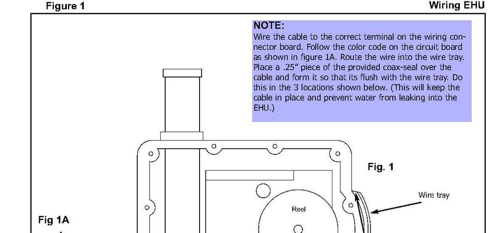

10 EHU Wiring Instructions 10
 but you want to ensure that the mounting pole does not shift or")
11 Mounting the BigIR (ground) The BigIR comes with a 1.5 OD aluminum mounting post, 2 feet in length (Figure 1 - D). If using guy wires, the antenna can be mounted directly into the ground without concrete (the guy wires will lock the antenna in place) but you want to ensure that the mounting pole does not shift or settle over time, using concrete to secure it in the ground is a good way to eliminate the potential for this problem. Position the mounting pole (machined end up) so that the bottom of the element housing is 8 to 10 inches above the ground (Figure 29). At this point you want to decide on your guy configuration and mount the guy bracket (s) and attach the guy wires before erecting the antenna (Figure 35, 36 & 37). No Guy Wires 50 mph One set of guy wires 70 mph Two sets of guy wires (optional bracket) 100 mph One guy wire connects to one side of the guy bracket and two guy wires connect to the other side of the guy bracket using the two security snaps (Figure 31). With the mounting post is in place and level and your guy assembly mounted, you are ready to erect the antenna. Now slide the small end of the flexible coupler (rubber boot) to the mounting post (Figure 41). This coupler is used to keep the antenna from potentially twisting in high winds. Pick up the antenna at the base (Figure 33) and slide the antenna housing onto the mounting pole until it firmly bottoms out. Place the larger end of the flexible coupler over the antenna housing tube (a small amount of bar soap or other lubricant will help the process). Tighten clamps on the coupler and secure the guy wires. Now you are ready to connect the radials! We recommend using a lug connector (crimped & soldered) at the end of your radials, and then tightening the lug onto the connector (ground) post shown in Figure 39. If you purchased the optional radial kits (Figure 28), you will notice there are 4 wires per set (ground radials), all soldered and crimped to a lug Figure 28 Ground radials connector. EHU Figure 29 Figure 31 8 to 10 in. Figure 33 11
12 Recommended Radials Figure 43 Ground Mounting: Min. of 12 - radials cut to the lowest frequency Elevated Mounting: Min. of 2 pre band trimmed to.1 x frequency Figure 35 Single Guy Configuration Figure 37 Double Guy Configuration 11ft Above Ground Bracket (Supplied) Second 15ft Above Ground Bracket (optional) First 7.5ft Above Ground Bracket (Supplied) Anchor Anchor Antenna Anchor Warning: A 11 ft radius and an even spread (120 deg) are the minimum dimensions required, when positioning the guy anchors, to achieve the stated wind ratings Figure 36 Figure 41 Figure 39 Mounting Tube Ground Flexible Coupler 8 to 10 in. 12


13 Installing the 80m Coil to an existing BigIR The 80m coil back plate will have 4 of its 8 holes that will align with 4 of the holes in your element housing unit (EHU). Remove the 4 bolts already in these 4 holes. Install the new bolts, spacers and coil to your element housing and tighten the new Nylok nuts as shown in (Figure 45 & Figure 47). WARNING: After connecting all of the wires, please make sure that the Control Cable and the Coax do not touch each other, this can cause the wires to arc and it will damage the Antenna. 4 SS bolts with 4 Nylon Spacers Figure 45 Figure 47 13
 of the coax producing radiation from the line.")

14 Optional (1:1) External Balun A balun is an electrical circuit used to help resolve the inherent problem of feeding an antenna with an electrically unbalanced (coax) feed line. It is intended to present an infinite impedance to any RF current that might otherwise flow on the outer conductor (shield) of the coax producing radiation from the line. This current, if high enough, can cause heat buildup and potential damage to the radio as well as a distorted radiation pattern. Coax Radio Why is it Optional?: In the normal configuration, ground mounted with 12 or more radials, the ground will bleed/ drain the unwanted RF signal from the coax shield. Ferrite Toroidal Core Balun Installation Antenna Figure 23 When Should You Use A Balun?: When elevating the base of a vertical antenna above the ground When only a few radials are used When the coax run is shorter than the radials When the ground condition is poor Unusual SWR readings on one band Balun Mounted on BigIR To install the balun (Figure 25) we suggest that you mount it as shown in Figure 27. There are two holes in the base of the balun that will line up with two screws in the end of the element housing unit next to the SO-239 connector. Remove these two screws and reinstall them through the balun then connect the PL-259 as shown in Figure 27. Your feed line will then plug into the SO-239 in the center of the balun. Optional External Balun Figure 27 Figure 25 14
15 All vertical monopoles need some form of counterpoise in which antenna image currents flow to work efficiently. This counterpoise usually consists of a system of radial wires placed either on the ground or elevated above ground. This is not an in depth publication but simply a general guide on installing and using the SteppIR verticals. There is much more information available in various publications if you need it. The ARRL Antenna Handbook is a good source for additional information. By following a few simple guidelines, you can obtain excellent performance from vertical antennas mounted on the ground or elevated above the ground. There are a number of verticals available that say no radials required, but they do have radials, in the form of a shortened, tuned counterpoise system. As you might expect, you pay a price for such a small counterpoise system - less efficiency. As you will see in the following pages, you can get fairly high efficiency with a relatively modest radial system that will far outperform small counterpoise systems. It should be noted that counterpoise systems are only good for curing near field losses caused by losses from the earth, which is a poor conductor of RF, even with good soil. There is nothing you can do about far field losses that reduce the signal strength and low angle radiation, except get to some saltwater. We briefly discuss salt water locations later on in this article. Ground Mount or Elevate? Ground Mounting: PROS The radials can be any length and they work on all frequencies Easy to mount Easy access Lower visual profile Eight to twelve 0.1 wavelength radials gives 60% - 65% efficiency (one set of 8-12 radials cut to 0.1 wavelength at lowest frequency) CONS Takes 120 radials to equal an elevated vertical with 2 resonant radials (90% efficient) Surrounding objects can reduce signal strength 15
16 Elevated Mounting: PROS + 90% efficient with two.25 wavelength radials Antenna is generally more in the clear, so surrounding objects don t cause as much attenuation A peaked metal roof will make a very good all-frequency radial system CONS Requires two.25 wavelength radials for each band of operation (radials interact, so spacing will affect length) Mounting is generally more involved Visually higher profile Must be mounted high enough that people won t walk into it Needs to be about.2 wavelengths high to get an ideal 50 ohm match Radials need at least a 20 slope to get a good match Involves adjusting and fine tuning the radial lengths Ground Mounting: If you chose to ground mount the vertical, pick a spot that will allow you the best chance of spreading your radials evenly around the antenna, and away from trees and other objects if possible. Mount the antenna within one foot of ground if possible, the closer to ground the better. Next, you will need to determine how much effort and wire you are willing to invest in this installation. The tradeoffs are as follows: 1. More radials equals higher efficiency (see Graph 1) 2. More short radials are generally better than a few long ones 3. If only a few radials are going to be used, they need not be very long 4. If you have very good earth (very few of us actually do), you can obtain good performance with very few radials % Efficiency Graph Number of Radials Number of radials 16
17 Four radials are what we consider to be the absolute minimum in average soil. How much you have to gain with a good radial system depends on how good your earth is. Most of us have poor earth conditions, so the radial system is important. The worse the earth is, the more can be gained with radials. Graph 2 shows a graph produced by Brian Edward (N2MF) that illustrates the relative signal gain you get with the radials and varying length over poor earth. With better earth, the gain difference between 4 radials and 120 radials will be about 2.5 db, as opposed to 4 db with poor earth N=120 N= Radials 96 Radials 2.4 N=48 48 Radials Relative Gain N=24 24 Radials 0 N=12 12 Radials Graph Radil Length in Wave length N=4 Radial length in wavelength 4 Radials If you are restricted to.1 wavelength radials there is not much advantage to using more than about 24 radials. You can see from Graph 3 that if more radials are used there is a huge advantage to making them longer. If you cannot lay the radials out in a symmetrical radial pattern, don t worry too much - it will distort your omni-directional pattern slightly but won t reduce your efficiency very much. Lay the radials out in the best manner possible given your situation. There are various ways to accomplish laying a radial system, including turning corners, etc. Good results are limited only to your creative energy and determination! Be aware that very high voltages can exist at the ends of radials, so be certain that no one can come into contact with them. It is a good idea to use insulated wire to protect from corrosion, and don t bury the radials any deeper than necessary, one to three inches is sufficient Graph 3 Sufficient Radial Length (wavelength) Number of Radials (N) Number of radials 17
18 Elevated Mounting: You can elevate a vertical just a few feet from the ground (4 feet for 20m, 8 feet for 40m) and get fairly good performance with just 2 radials (elevated as well) per band of operation. The problem is you won t have a very good match to 50 ohms, and the close proximity of the earth will degrade the signal - especially if it is poor earth. For ideal matching, we recommend.2 wavelength (about 15 feet on 20m and 30 feet on 40m) at the lowest planned frequency of operation As the height decreases below.2 wavelength, the ground losses start to increase, unless you have very good ground. When a vertical is raised off the ground the impedance drops fairly rapidly from 36 ohms (Over perfect ground or with many radials it will be close to 36 ohms, over real ground it is generally ohms) to about 22 ohms when.3 wavelength is reached. This would make a pretty poor match to 50 ohms, so a couple of tricks are in order. Once you elevate a vertical, two radials are all you really need. It is important that you try to keep a 180 angle between the two (opposed, directly in line) for the best pattern. Spread the radials out as far as possible to reduce interaction, if they are less than a foot apart it can be difficult to get a good match on all bands. To facilitate a match to 50 ohms you can angle the radials downward, this raises the impedance of the antenna as you increase the angle downward. Graph 4 shows the approximate relationship of radial angle to impedance: Graph 4 Radial Droop Angle Antenna Impedance 0 = 22 Ohms 10 = 28 ohms 20 = 35 ohms 30 = 47 ohms 40 = 53 ohms 50 = 55 ohms Note: above 50 results in diminishing returns 18


19 Can t get enough droop angle to achieve a good match? Simply adjust the antenna element slightly longer than the factory 1/4 wavelength (up to 20% longer) settings and the impedance will rise. This will cause the radials to be too long, so they may need to be pruned a bit. Be aware that increasing the antenna 2% to 3% longer may require radials to be 5% to 7% shorter. Once you have a good match, replace the factory default values by saving the new antenna (to do this you will use the create, modify feature in the setup mode). When the vertical is elevated you can get away with just one resonant radial, however, the pattern won t be omni-directional. You will have -12 db to 15 db null in one direction Using a Vertical in on or Near Salt Water: If you are lucky enough to have a dock over salt water, a vertical can offer unparalleled performance for low angle DX. Simply mount the vertical to the dock and attach two radials per band of operation. They can be stapled right to the dock if it is non-metallic. Mounting the vertical in ground flooded by salt water a couple of times per day can be equally effective. Proximity to the ocean improves the far field loss of a vertical and allows very low angle radiation - get as close to the water as possible to enhance performance. Due to the fact that RF does not penetrate more than 2 inches into the water, direct coupling (a wire in the water) is difficult. Objects like metal floats or boats, providing they are large enough, can make good grounds in salt water. If you are using a metal boat or large metal object, corrosion is no longer a problem because the large surface capacitively couples to the water. When using a small metal float (3 ft x 3 ft is just enough to connect to salt water), you want to be certain that the metal does not corrode over time. For long term immersion, Monel is a good (but fairly expensive ) choice. 19


20 DB 18 Control Cable Splice Assembly Instructions 20

21 Wiring Diagram- DB25 Cable Splice 21
22 Warranty / Contact Information In the event you have a problem with your SteppIR product, please contact: Tech support: support@steppir.com If you need to return your antenna for repair, please go to fill out the Return for Repair form, print a copy and put it into the package that you send back to SteppIR. STEPPIR ANTENNAS LIMITED PRODUCT WARRANTY Our products have a limited warranty against manufacturers defects in materials or construction for two (2) years from date of shipment. Do not modify this product or change physical construction without the written consent of Fluidmotion Inc, dba SteppIR Antennas. This limited warranty is automatically void if the following occurs: improper installation, unauthorized modification and physical abuse, or damage from severe weather that is beyond the product design specifications. SteppIR Antenna s responsibility is strictly limited to repair or replacement of defective components, at SteppIR Antennas discretion. SteppIR Antennas will not be held responsible for any installation or removal costs, costs of any ancillary equipment damage or any other costs incurred as a result of the failure of our products. In the event of a product failure, a return authorization is required for warranty repairs. This can be obtained at Shipping instructions will be issued to the buyer for defective components, and shipping charges to the factory will be paid for by the buyer. SteppIR will pay for standard shipping back to the buyer. The manufacturer assumes no further liability beyond repair or replacement of the product. 22
23
24
2 Element Yagi Instruction Manual
 2 Element Yagi Instruction Manual 3Y0X Peter 1 DXpedition 2006 Manual REV 3.0 September 2012 2112 116TH AVE NE SUITE 1-5, BELLEVUE WA, 98004 WWW.STEPPIR.COM TEL: (425)-453-1910 FAX: (425)-462-4415 SteppIR
General Product Brochure
 General Product Brochure SteppIR Antennas 2112 116th Ave NE #1-5 Bellevue, WA 98004 Tel: 425.453.1910 sales@steppir.com www.steppir.com SteppIR - Why Compromise? The SteppIR antenna was conceived to solve
2 Element Yagi Instruction Manual
 2 Element Yagi Instruction Manual 3Y0X Peter 1 DXpedition 2006 Manual REV 3.0 December 2012 2112 116TH AVE NE SUITE 1-5, BELLEVUE WA, 98004 WWW.STEPPIR.COM TEL: (425)-453-1910 FAX: (425)-462-4415 SteppIR
3 Element Yagi Instruction Manual
 Yagi Dipole Vertical (Patent # 6,677,914) 3 Element Yagi Instruction Manual Antarctica at 75 mph SteppIR Antennas 2112 116th Ave NE, Suite 2-5 - Bellevue, WA 98004 Tel: 425-453-1910 Fax: 425-462-4415 Tech
3 Element Yagi Instruction Manual
 Yagi Dipole Vertical (Patent # 6,677,914) 3 Element Yagi Instruction Manual Antarctica at 75 mph SteppIR Antennas 2112-116th Ave NE, Suite 2-5, Bellevue, WA 98004 Tel: 425-453-1910 Fax: 425-462-4415 Tech
Installation Instructions Hustler 6-BTV Trap Vertical
 Installation Instructions Hustler 6-BTV Trap Vertical ASSEMBLY 1. Check the package contents against the parts list on page 2. 2. WARNING. Installation of this product near power lines is dangerous. For
Installation Instructions Hustler 6-BTV Trap Vertical
 Installation Instructions Hustler 6-BTV Trap Vertical ASSEMBLY 1. Check the package contents against the parts list on page 2. 2. WARNING. Installation of this product near power lines is dangerous. For
INSTRUCTION MANUAL. Model 18AVQII Five Band Vertical Antenna 10, 15, 20, 40, 80 Meter. General Description. Theory of Operation
 Model 18AVQII Five Band Vertical Antenna 10, 15, 20, 40, 80 Meter 308 Industrial Park Road Starkville, MS 39759 (662) 323-9538 Fax: (662) 323-5803 INSTRUCTION MANUAL General Description The Hy-Gain 18AVQII
INSTRUCTION MANUAL. Model 18AVQII Five Band Vertical Antenna 10, 15, 20, 40, 80 Meter
 Model 18AVQII Five Band Vertical Antenna 10, 15, 20, 40, 80 Meter 308 Industrial Park Road Starkville, MS 39759 (662) 323-9538 Fax: (662) 323-5803 INSTRUCTION MANUAL General Description The Hy-Gain 18AVQII
MFJ-2982 Feather-Lite 80-6 Meter Vertical Antenna
 MFJ-2982 Feather-Lite 80-6 Meter Vertical Introduction: The MFJ-2982 is a lightweight 31-foot fiberglass antenna designed to mount on any convenient post, mast, or a suitable wide-stance tripod such as
K1FO 12 ELEMENT 144/147 MHz YAGI
 K1FO 12 ELEMENT 144/147 MHz YAGI WARNING: INSTALLATION OF THIS PRODUCT NEAR POWER LINES IS DANGEROUS. FOR YOUR SAFETY FOLLOW THE INSTALLATION DIRECTIONS. Ariane Arrays, Inc. Copyright 2006 201 Hopedale
M2 Antenna Systems, Inc. Model No: 2M7
 M2 Antenna Systems, Inc. Model No: 2M7 SPECIFICATIONS: Model... 2M7 Frequency Range... 144 To 148 MHz *Gain... 12.3 dbi Front to back... 20 db Typical Beamwidth... E=43 H=50 Feed type... T Match Feed Impedance....
PAC-12 Kit Contents. Tools Needed Soldering iron Phillips screwdriver Wire stripper Wrenches, 7/16 and 1/2 Terminal crimp tool Pliers Solder
 PAC-2 Kit Contents Part Quantity Screws: 8/32 x 3/8 Screws: 8-32 x 5/6 Screw: 8-32 x /4 #8 internal tooth washers #8 solder lug ring terminals Bolt: Aluminum, /4-20 x.5 /4 internal tooth washer Nut: Aluminum
NEW Plastic Sweep Installation Instructions 40/30 Loop Antennas
 40/30 Loop Antennas PG 1 Preparing the telescoping pole tips for the 40/30 loop elements Extend the telescoping poles to full length by firmly locking each section of the pole in place. A good methodology
INSTRUCTION MANUAL. Specifications Electrical. Front-To-Back Ratio VSWR at Resonance Less than 1.5:1 Nominal Impedance. Mechanical
 300 Industrial Park Road, Starkville, MS 39759 Ph: (662) 323-8538 FAX: (662) 323-6551 TH-3JRS Tri-band HF 3 Elements Beam Covers 10, 15 and 20 Meters INSTRUCTION MANUAL WARNING Installation of this product
SteppIR Yagi / Dipole Instruction Manual
 6WHSS,5 TM Yagi z Dipole zvertical (Patent Pending) SteppIR Yagi / Dipole Instruction Manual SteppIR Antennas 23831 S.E. Tiger MT. RD. Issaquah, WA 98027 Tel: 425-391-1999 Fax: 425-391-8377 Toll Free:
Model VB-23FM 2-Meter 3-Element Beam
 308 Industrial Park Road Starkville, MS 39759 USA Ph: (662) 323-9538 FAX: (662) Model VB-23FM 2-Meter 3-Element Beam [ INSTRUCTION MANUAL Figure 1 Overall View and Boom Detail GENERAL DESCRIPTION This
Model S9v. 43 Multiband Vertical Antenna Installation Guide
 Model S9v 43 Multiband Vertical Antenna Installation Guide. WARNING: INSTALLATION OF THIS PRODUCT NEAR POWERLINES IS DANGEROUS. FOR YOUR SAFETY, FOLLOW THE INSTALLATION DIRECTIONS. INTRODUCTION Thank you
MI: (Secure this number someplace, for possible future need) SPECIFICATIONS:
 SPECIFICATIONS:") 6C ASSEMBLY INSTRUCTIONS ANTENNA MODEL T6 MI: 030927 (Secure this number someplace, for possible future need) SPECIFICATIONS: FORWARD GAIN 5.1 dbd F:B RATIO 15-25 db (Rises with frequency) FREQUENCY COVERAGE
6C ASSEMBLY INSTRUCTIONS ANTENNA MODEL T6 MI: 030927 (Secure this number someplace, for possible future need) SPECIFICATIONS: FORWARD GAIN 5.1 dbd F:B RATIO 15-25 db (Rises with frequency) FREQUENCY COVERAGE
INSTRUCTION MANUAL. Specifications Mechanical. 1 5/8 to 2 1/16 O.D. (41mm to 52mm)
") 308 Industrial Park Road Starkville, MS 39759 USA Ph: (662) 323-9538 FAX: (662) 323- General Description Model VB-25FM 2-Meter 5 Elements Beam INSTRUCTION MANUAL This antenna is a 5-element, 2-meter beam
308 Industrial Park Road Starkville, MS 39759 USA Ph: (662) 323-9538 FAX: (662) 323- General Description Model VB-25FM 2-Meter 5 Elements Beam INSTRUCTION MANUAL This antenna is a 5-element, 2-meter beam
Basic Wire Antennas. Part II: Loops and Verticals
 Basic Wire Antennas Part II: Loops and Verticals A loop antenna is composed of a single loop of wire, greater than a half wavelength long. The loop does not have to be any particular shape. RF power can
Directive Systems & Engineering 2702 Rodgers Terrace Haymarket, VA
 Directive Systems & Engineering 2702 Rodgers Terrace Haymarket, VA 20169 1628 www.directivesystems.com 703 754 3876 K1JX DESIGNED 6 ELEMENT 50 MHZ YAGI, DSEJX6 50 INTRODUCTION The Directive Systems DSEJX6-50
Cushcraft. Amateur Radio Antennas DB-46M8EL. Dual band 6 and 4 Meter, 8 Element Beam Antenna INSTRUCTION MANUAL
 Cushcraft Amateur Radio Antennas DB-46M8EL Dual band 6 and 4 Meter, 8 Element Beam Antenna INSTRUCTION MANUAL CAUTION: Read All Instructions Before Operating Equipment VERSION 1B Cushcraft Amateur Radio
A IVE-BAND, TWO-ELEMENT H QUAD
 A IVE-BAND, TWO-ELEMENT H QUAD Two quad designs are described in this article, both nearly identical. One was constructed by KC6T from scratch, and the other was built by Al Doig, W6NBH, using modified
Chapter 6 Antenna Basics. Dipoles, Ground-planes, and Wires Directional Antennas Feed Lines
 Chapter 6 Antenna Basics Dipoles, Ground-planes, and Wires Directional Antennas Feed Lines Some General Rules Bigger is better. (Most of the time) Higher is better. (Most of the time) Lower SWR is better.
LJ element beam for 10 or 12 meters INSTRUCTION MANUAL. CAUTION: Read All Instructions Before Operating Equipment
 LJ-113 3 element beam for 10 or 1 meters INSTRUCTION MANUAL CAUTION: Read All Instructions Before Operating Equipment 308 Industrial Park Road Starkville, MS 39759 USA Tel: 66-33-9538 Fax: 66-33-6551 VERSION
MFJ-1835K34 40,30 METER ADD ON KIT FOR THE MFJ-1835 COBWEB ANTENNA INSTRUCTION MANUAL. CAUTION: Read All Instructions Before Operating Equipment
 MFJ-1835K34 40,30 METER ADD ON KIT FOR THE MFJ-1835 COBWEB ANTENNA INSTRUCTION MANUAL CAUTION: Read All Instructions Before Operating Equipment 300 Industrial Park Road Starkville, MS 39759 USA Tel: 662-323-5869
Cushcraft. Amateur Radio Antennas LFA-6M5EL. 6 Meter 5 Element Loop Feed Antenna INSTRUCTION MANUAL
 Cushcraft Amateur Radio Antennas LFA-6M5EL 6 Meter 5 Element Loop Feed Antenna INSTRUCTION MANUAL CAUTION: Read All Instructions Before Operating Equipment VERSION 1A Cushcraft Amateur Radio Antennas 308
A short, off-center fed dipole for 40 m and 20 m by Daniel Marks, KW4TI
 A short, off-center fed dipole for 40 m and 20 m by Daniel Marks, KW4TI Version 2017-Nov-7 Abstract: This antenna is a 20 to 25 foot long (6.0 m to 7.6 m) off-center fed dipole antenna for the 20 m and
Table of Contents. MFJ-1778 G5RV Multiband Antenna
 Table of Contents MFJ-1778 G5RV Multiband Antenna Introduction... 1 Theory Of Operation... 1 80 meter band:... 1 40 meter band:... 1 30 meter band:... 2 20 meter band:... 2 17 meter band:... 2 15 meter
AV-12AVQ Triband HF Vertical 10, 15, 20-Meter INSTRUCTION MANUAL
 308 Industrial Park Starkville, MS 39759 USA Ph: (662) 323-9538 FAX: (662) 323-6551 AV-12AVQ Triband HF Vertical 10, 15, 20-Meter INSTRUCTION MANUAL General Description This vertical antenna is designed
M2 Antenna Systems, Inc. Model No: KT31WARC
 M2 Antenna Systems, Inc. Model No: KT31WARC SPECIFICATIONS: Model... KT31WARC Frequency Range... 10.1-10.15 MHz **Selectable Frequency Range... 14.0-14.35 MHz **Selectable... (175 KHz / 2:1 VSWR Nominal)
Some hints/tips on how to assemble nice COAX TRAPS!
 Some hints/tips on how to assemble nice COAX TRAPS! Before we start to assemble our traps, here some general info as introduction : Coax traps are cheap, easy to assemble in a reproducible manner, very
MFJ ENTERPRISES, INC.
 Model MFJ-2910 INSTRUCTION MANUAL CAUTION: Read All Instructions Before Operating Equipment MFJ ENTERPRISES, INC. 300 Industrial Park Road Starkville, MS 39759 USA Tel: 662-323-5869 Fax: 662-323-6551 VERSION
TZ-RD-1740 Rotary Dipole Instruction Manual
 TZ-RD-1740 17/40m Rotary Dipole Instruction Manual The TZ-RD-1740 is a loaded dipole antenna for the 40m band and a full size rotary dipole for the 17m band. The antenna uses an aluminium radiating section
Build a 12/17 Meter Trap Dipole Phil Salas AD5X
 Build a 12/17 Meter Trap Dipole Phil Salas AD5X Introduction Why a 12/17 meter rotatable dipole? Well, many folks have verticals for the lower bands, and multi-band dipoles or beams for 20-, 15-, and 10
M2 Antenna Systems, Inc. Model No: 2M4
 M2 Antenna Systems, Inc. Model No: 2M4 SPECIFICATIONS: Model... 2M4 Frequency Range... 144 To 148 MHz *Gain... 9.6 dbi Front to back... 20 db Typical Beamwidth... E=54 H=74 Feed type... T Match Feed Impedance....
ASSEMBLY AND INSTALLATION INSTRUCTIONS R , 12, 15, 17, 20, 30, 40 Meters (5/99) COMMUNICATIONS ANTENNAS
 COMMUNICATIONS ANTENNAS") ASSEMBLY AND INSTALLATION INSTRUCTIONS R7000 10, 12, 15, 17, 20, 30, 40 Meters COMMUNICATIONS ANTENNAS 951465 (5/99) WARNING THIS ANTENNA IS AN ELECTRICAL CONDUCTOR. CONTACT WITH POWER LINES CAN RESULT
ASSEMBLY AND INSTALLATION INSTRUCTIONS R7000 10, 12, 15, 17, 20, 30, 40 Meters COMMUNICATIONS ANTENNAS 951465 (5/99) WARNING THIS ANTENNA IS AN ELECTRICAL CONDUCTOR. CONTACT WITH POWER LINES CAN RESULT
HFp. User s Guide. Vertical. entenna. 7 MHz 30 MHz Amateur Radio Antenna Plus 6-Meters
 User s Guide HFp Vertical 7 MHz 30 MHz Amateur Radio Antenna Plus 6-Meters The Ventenna Co. LLC P.O. Box 2998, Citrus Heights, CA, 956 www.ventenna.com entenna Table of Contents The HFp Antenna -------------------------------------------------------------------
INSTRUCTION MANUAL V-42R. Dual Band Collinear Gain Vertical for MHz and GENERAL DESCRIPTION
 308 Industrial Park Road, Starkville, MS 39759 USA Ph: (662) 323-9538 FAX: (662) 323-6551 V-42R Dual Band Collinear Gain Vertical for 144-148 MHz and 436-450 INSTRUCTION MANUAL GENERAL DESCRIPTION The
6M HALO VERSON II + OPTIONAL 2M GROUND PLANE
 The halo is an omnidirectional, horizontally polarized antenna with about the same gain as a dipole but without the low elevation nulls off the ends (+5.5 to +3.5dBi variation for the Halo vs. +7.9 to
M2 Antenna Systems, Inc. Model No: 2M5WL
 M2 Antenna Systems, Inc. Model No: 2M5WL SPECIFICATIONS: Model... 2M5WL Frequency Range... 144 To 148 MHz *Gain... 16.84 dbi Front to back... 22 db Typical Beamwidth... E=26 H=29 Feed type... T Match Feed
JK-65 Five Element 6M Yagi
 JK-65 Five Element 6M Yagi PO Box 266, Croton Falls, NY 10519-0266 845.228.8700 (TEL) 845.279.5526 (FAX) info@jkantennas.com Page 1 of 8 JK Antennas Limited Warranty and Liability JK Antennas ( Manufacturer
60 Meter Mono-Band Conversion Kit for the DXE-MBVE-5A Multi-Band Vertical Antenna
 60 Meter Mono-Band Conversion Kit for the DXE-MBVE-5A Multi-Band Vertical Antenna DXE-MBVE-5A60MCK DXE-MBVE-5A60MCK-INS Revision 0a DX Engineering 2017 1200 Southeast Ave. - Tallmadge, OH 44278 USA Phone:
TW4040. The Adventurer Monobander INSTRUCTION MANUAL. TransWorld Antennas
 TW4040 The Adventurer Monobander TransWorld Antennas INSTRUCTION MANUAL Contents 1 Limited Warranty 3 2 Important Safety Information 4 3 Specifications 3.1 Mechanical 4 3.2 Electrical 4 3.3 VSWR Performance
Directive Systems & Engineering 2702 Rodgers Terrace Haymarket, VA
 Directive Systems & Engineering 2702 Rodgers Terrace Haymarket, VA 20169-1628 www.directivesystems.com 703-754-3876 25 Element 7.4 wl. K1FO Designed Yagi, Model DSEFO432-25 ELECTRICAL SPECIFICATIONS Frequency
UrbanBeam Yagi Assembly Manual
 UrbanBeam Yagi Assembly Manual This assembly manual is intended to be printed in full COLOR. If the manual is printed in black and white, many important details could be lost. REV 1.03 08/23/2018 Page
The W3FF Portable Dipole
 The W3FF Portable Dipole This is the antenna I designed for my 'walking portable' station. It is a dipole constructed out of the plastic plumbing pipe CPVC. There are telescoping whips at the ends of each
Alpha Delta Communications, Inc. Model DX-OCF Off-Center-Fed 7 Band Antenna
 Alpha Delta Communications, Inc. Model DX-OCF Off-Center-Fed 7 Band Antenna 75/80, 40, 20, 17, 12, 10, and 6 meters (50.0-51.0 MHz) NO TUNER REQUIRED! Installation Instructions One leg is 45 ft., the other
Pacific Antenna 20 and 40M Lightweight Dipole Kit
 Pacific Antenna 20 and 40M Lightweight Dipole Kit Antenna diagram showing configuration and lengths when assembled 7 8 16 9 16 9 Description The Pacific Antenna lightweight dual band dipole kit provides
MFJ ENTERPRISES, INC.
 Model MFJ-2911 INSTRUCTION MANUAL CAUTION: Read All Instructions Before Operating Equipment MFJ ENTERPRISES, INC. 300 Industrial Park Road Starkville, MS 39759 USA Tel: 662-323-5869 Fax: 662-323-6551 VERSION
JK M Hi-Q Coil Loaded Rotatable Dipole Version
 JK-401 40M Hi-Q Coil Loaded Rotatable Dipole 2018 Version 72 Grays Bridge Road, Unit D, Brookfield, CT 06804 845.228.8700 (TEL) 845.279.5526 (FAX) info@jkantennas.com LAST UPDATED: 02-01-2018 JK Antennas
40 Meter Vertical Antenna
 40 Meter Vertical Antenna COM-40VA COM-40VA-INS-Revision 1 COMTEK SYSTEMS 2016 1200 Southeast Ave. - Tallmadge, OH 44278 USA Phone: (800) 777-0703 Technical Support and International: (330) 572-3200 Fax:
INSTRUCTION MANUAL ORDER NO. V3R MODEL V3R. Collinear Gain Vertical for MHz
 ORDER NO. V3R MODEL V3R Collinear Gain Vertical for 216-225 MHz INSTRUCTION MANUAL General Description The new Hy-Gain V3R VHF antenna is a collinear 5/8-wave omnidirectional vertical antenna for the 216-225
Cisco Aironet Omnidirectional Mast Mount Antenna (AIR-ANT2506)
") Cisco Aironet Omnidirectional Mast Mount Antenna (AIR-ANT2506) This document outlines the specifications, describes the omnidirectional mast mount antenna, and provides instructions for mounting it. Designed
Cisco Aironet Omnidirectional Mast Mount Antenna (AIR-ANT2506) This document outlines the specifications, describes the omnidirectional mast mount antenna, and provides instructions for mounting it. Designed
CP6A. 6 Band Trap Vertical 75-6m
 CP6A 6 Band Trap Vertical 75-6m Instruction Sheet The CP6A is a multi-band trap-vertical antenna for HF bands, covering the 75*, 40, 20, 15, 10m & 6m amateur bands. Made from heavy duty aluminum, the CP6A
Cisco Aironet 13.5-dBi Yagi Mast Mount Antenna (AIR-ANT1949)
") Cisco Aironet 13.5-dBi Yagi Mast Mount Antenna (AIR-ANT1949) Overview This document describes the 13.5-dBi Yagi mast mount antenna and provides instructions for mounting it. The antenna operates in the
Cisco Aironet 13.5-dBi Yagi Mast Mount Antenna (AIR-ANT1949) Overview This document describes the 13.5-dBi Yagi mast mount antenna and provides instructions for mounting it. The antenna operates in the
INSTRUCTION MANUAL for MODEL TH6-DX "THUNDERBIRD" (389)
") INSTRUCTION MANUAL for MODEL TH6-DX "THUNDERBIRD" (389) HY-GAIN ELECTRONICS CORPORATION, N. E. Hwy #6 at Stevens Creek, Lincoln, Nebraska 65801 Telephone 434-6331 INTRODUCTION Ely-Gain's new Model TH6-DX
INSTRUCTION MANUAL for MODEL TH6-DX "THUNDERBIRD" (389) HY-GAIN ELECTRONICS CORPORATION, N. E. Hwy #6 at Stevens Creek, Lincoln, Nebraska 65801 Telephone 434-6331 INTRODUCTION Ely-Gain's new Model TH6-DX
INSTRUCTION MANUAL VB-66DX. 6-Meter 6-Element Beam. Preparation For Assembly. General Description
 VB-66DX 308 Industrial Park Road Starkville, MS 39759 USA Ph: (662) 323-9538 FAX: (662) 323-6551 6-Meter 6-Element Beam INSTRUCTION MANUAL General Description The Hy-Gain Model 66DX is a full sized 6-
MODEL DB-1015A 10- and 15-Meter Duo-Band Antenna Order No. 330
 MODEL DB-1015A 10- and 15-Meter Duo-Band Antenna Order No. 330 HY-GAIN ELECTRONICS CORPORATION 8601 Northeast Highway 6 Lincoln, Nebraska 68505 Telephone 464-9151 Area Code 402 TABLE OF CONTENTS page SECTION
2014 MFJ ENTERPRISES, INC.
 Model MFJ-1907 INSTRUCTION MANUAL CAUTION: Read All Instructions Before Operating Equipment MFJ ENTERPRISES, INC. 300 Industrial Park Road Starkville, MS 39759 USA Tel: 662-323-5869 Fax: 662-323-6551 VERSION
CrankIR Portable Antenna System Assembly & Instruction Manual
 CrankIR Portable Antenna System Assembly & Instruction Manual This assembly manual is intended to be printed in full COLOR. If the manual is printed in black and white, many important details could be
TENNADYNE. Aluminum with a PhD. Tennadyne ASSEMBLY INSTRUCTIONS MODEL: T Log Periodic Antennas SPECIFICATIONS:
 TENNADYNE Aluminum with a PhD ASSEMBLY INSTRUCTIONS MODEL: T10-100224 SPECIFICATIONS: FREQUENCY COVERAGE 13-33 MHz FORWARD GAIN 6.1 dbd ½ POWER BEAMWIDTH 52 DEGREES F:B RATIO To 25 Db (Rises with frequency)
M2 Antenna Systems, Inc. Model No: 20M5LD
 M2 Antenna Systems, Inc. Model No: 20M5LD SPECIFICATIONS: Model... 20M5LD Frequency Range... 14.0 14.350 MHz *Gain (Full Band)... 10.2 dbi Typical Front to back... 23 db Typical Beamwidth... E=50 / H=66
4/29/2012. General Class Element 3 Course Presentation. Ant Antennas as. Subelement G9. 4 Exam Questions, 4 Groups
 General Class Element 3 Course Presentation ti ELEMENT 3 SUB ELEMENTS General Licensing Class Subelement G9 Antennas and Feedlines 4 Exam Questions, 4 Groups G1 Commission s Rules G2 Operating Procedures
USERS MANUAL for the. FB5 Antenna. a personal non-commercial project of the Florida Boys
 USERS MANUAL for the FB5 Antenna a personal non-commercial project of the Florida Boys AB4ET Dec.2003 1 The FB5 Antenna USERS MANUAL INDEX 1.0. Introduction 2.0. Design 3.0. Construction 4.0. Electrical
EH-20 20m antenna. By VE3RGW
 EH-20 20m antenna By VE3RGW Equivalent circuit of EH-20 antenna system. Upper cylinder Lower cylinder Phasing coil Common mode radiator Tune coil RF choke or 14MHz trap 50ohm coaxial cable 0-150pF (case
Yagi and Omni Antennas Installation Manual
 Yagi and Omni Antennas Installation Manual 25500445 Rev. A0 0218 Printed in U.S.A. Copyright 2018 Federal Signal Corporation Limited Warranty This product is subject to and covered by a limited warranty,
N5PUV s 4 Band Fan Dipole Experiment. Using the New SRI (Stanford Research Institute) Method
 Method") N5PUV s 4 Band Fan Dipole Experiment Using the New SRI (Stanford Research Institute) Method Goals of Experiment Develop a Multi-band Antenna that does NOT require a tuner Build using the new, easier tuning
N5PUV s 4 Band Fan Dipole Experiment Using the New SRI (Stanford Research Institute) Method Goals of Experiment Develop a Multi-band Antenna that does NOT require a tuner Build using the new, easier tuning
Model S9v Multiband Vertical Antenna Installation Guide
 Model S9v31 31 Multiband Vertical Antenna Installation Guide WARNING: INSTALLATION OF THIS PRODUCT NEAR POWERLINES IS DANGEROUS. FOR YOUR SAFETY, FOLLOW THE INSTALLATION DIRECTIONS. INTRODUCTION Thank
Nick Garner N3WG and George Zafiropoulos KJ6VU
 Nick Garner N3WG and George Zafiropoulos KJ6VU Introduction Over the last few years, there has been a significant increase in the number of radio amateurs interested in portable operating. This is due
Installation Instructions Hustler Collinear Two Meter Fixed Station Antenna Master Gainer Model G6-144B
 Installation Instructions Hustler Collinear Two Meter Fixed Station Antenna Master Gainer Model Warning INSTALLATION OF THIS PRODUCT NEAR POWER LINES IS DANGEROUS. FOR YOUR SAFETY, FOLLOW THE INSTALLATION
4 Antennas as an essential part of any radio station
 4 Antennas as an essential part of any radio station 4.1 Choosing an antenna Communicators quickly learn two antenna truths: Any antenna is better than no antenna. Time, effort and money invested in the
This file was downloaded from the website of G7SYW.
 This file was downloaded from the website of G7SYW http://www.g7syw.co.uk ASSEMBLY AND INSTALLATION INSTRUCTIONS Five-Band High-Performance Mini-Vertical Antenna 951495 (8/01) WARNING THIS ANTENNA IS AN
DB18 Yagi Assembly Manual
 DB18 Yagi Assembly Manual EA3PW This assembly manual is intended to be printed in full COLOR. If the manual is printed in black and white, many important details could be lost. REV 10.2 02/25/2014 Page
DB Duo-Monoband Beam 7 - Element, 12 and 17 Meter INSTRUCTION MANUAL. General Description
 308 Industrial Park Road Starkville, MS 39759 USA Ph: (662) 323-9538 FAX: (662) 323-6551 DB- 1217 Duo-Monoband Beam 7 - Element, 12 and 17 Meter INSTRUCTION MANUAL General Description The Hy-Gain DB-1217
M2 Antenna Systems, Inc. Model No: 20M6-125
 M2 Antenna Systems, Inc. Model No: 20M6-125 SPECIFICATIONS: Model... 20M6-125 Frequency Range... 14.0 14.350 MHz *Gain, (FS) / Over gnd... 11.19dBi / 16.6dBi @70 Front to back... 25 db Typical Beamwidth...
HFp. User s Guide. Vertical. entenna. 7 MHz 30 MHz Amateur Radio Antenna
 User s Guide HFp Vertical 7 MHz 30 MHz Amateur Radio Antenna The Ventenna Co. LLC P.O. Box 2998, Citrus Heights, CA, 95611 www.ventenna.com entenna Table of Contents The HFp Antenna -------------------------------------------------------------------
Tarheel Antennas, Inc.
 Tarheel Antennas, Inc. Instruction Manual for the Model 100A-HP Continuous Coverage HF Antenna PROUDLY MADE IN THE UNITED STATES OF AMERICA 18511 CR 304 St. Joseph, MO 64505 816-671-9409 / 816-364-2619
CP6 6 Band Trap Vertical 80-6m
 CP6 6 Band Trap Vertical 80-6m Instruction Sheet The CP6 is a multi-band trap-vertical antenna for HF bands, covering the 80*, 40, 20, 15, 10m & 6m amateur bands. Made from heavy duty aluminum, the CP6
LC31L-BAT Link Coupler
 Instruction Manual For the LC31L-BAT Link Coupler 09 March 2018 2012-2018 by Ralph Hartwell Spectrotek Services All rights reserved 2 RADIO FREQUENCY WARNING NOTICE If the LC31L-BAT is installed incorrectly
Spiderbeam Balun Construction Guide
 BALUN CONSTRUCTION GUIDE Ver. 1.0 1 The components of the Balun Kit are in a plastic bag. Most of the components are inside the plastic case of the balun. The aluminum U-profile and the RG-142 Teflon Coax
The DBJ-1: A VHF-UHF Dual-Band J-Pole
 By Edison Fong, WB6IQN The DBJ-1: A VHF-UHF Dual-Band J-Pole Searching for an inexpensive, high-performance dual-band base antenna for VHF and UHF? Build a simple antenna that uses a single feed line for
MHz. ANT150D, D3, D6-9 DIPOLE AND DIPOLE ARRAY 1 TO 9 dbd
 138-174 MHz ANTD, D3, D6-9 DIPOLE AND DIPOLE ARRAY 1 TO 9 dbd The Telewave ANTD series consists of single, dual, and 4-element di pole array antennas with a precision phasing harness for optimum per formance.
REP Design LLC. 193 Winding Ridge Rd, Southington, CT INSTALLATION INSTRUCTIONS:
 REP Design LLC 193 Winding Ridge Rd, Southington, CT 06489 1-860.426.1894 n7emw@cox.net www.repdesign.us INSTALLATION INSTRUCTIONS: SHD-SO239 Super Heavy Duty SO-239Antenna Mounting System Thank you for
BUILD A HIGH PERFORMANCE TWO ELEMENT TRI-BAND CUBICAL QUAD. By Bob Rosier K4OCE INTRODUCTION THEORY AND GENERAL INFORMATION
 BUILD A HIGH PERFORMANCE TWO ELEMENT TRI-BAND CUBICAL QUAD INTRODUCTION By Bob Rosier K4OCE Lots of DX can be worked with a dipole at the QRP level, however, a beam will obviously give you additional gain
MFJ-219/219N 440 MHz UHF SWR Analyzer TABLE OF CONTENTS
 MFJ-219/219N 440 MHz UHF SWR Analyzer TABLE OF CONTENTS Introduction...2 Powering The MFJ-219/219N...3 Battery Installation...3 Operation Of The MFJ-219/219N...4 SWR and the MFJ-219/219N...4 Measuring
AD5X. The 43-Foot Vertical. Phil Salas - AD5X Phil Salas AD5X. Richardson, Texas
 The 43-Foot Vertical Phil Salas - AD5X ad5x@arrl.net Outline Why a vertical? Ground Losses and Antenna Efficiency Why a 43-foot vertical? SWR-related coax and unun losses Matching Networks for 160- and
Technician License. Course
 Technician License Course Technician License Course Chapter 4 Lesson Plan Module - 10 Practical Antennas The Dipole Most basic antenna The Dipole Most basic antenna The Dipole Total length is ½ wavelength
THE W3FF HOMEBREW BUDDIPOLE
 THE W3FF HOMEBREW BUDDIPOLE A PORTABLE ANTENNA DESIGN FOR AMATEUR RADIO History of the Buddipole In January of 2000, I began experimenting with a walking portable ham station. Since then, thousands of
Hardware Store 40m Magnetic Loop Antenna for Regional and EMCOM Use. Richard Bono NO5V. QST Antenna Design Competition 80 through 10 meter entry
 Hardware Store 40m Magnetic Loop Antenna for Regional and EMCOM Use Richard Bono NO5V QST Antenna Design Competition 80 through 10 meter entry Overview: This describes a field deployable magnetic loop
Pacific Antenna 20 and 40M Lightweight Dipole Kit
 Pacific Antenna 20 and 40M Lightweight Dipole Kit Diagram showing configuration and approximate lengths 8 3 16 9 16 9 8 3 Description The Pacific Antenna lightweight dual band, trap dipole kit provides
AD5X. Low Cost HF Antennas & Accessories. Phil Salas - AD5X Phil Salas AD5X. Richardson, Texas
 Low Cost HF Antennas & Accessories Phil Salas - AD5X ad5x@arrl.net PVC Tubing PVC pipe: Considers the inside diameter (ID) of the pipe. For PVC pipe (schedule 40): 1/2" PVC pipe has an ID of 0.6" and an
Pacific Antenna 20 and 40M Lightweight Dipole Kit
 Pacific Antenna 20 and 40M Lightweight Dipole Kit Diagram showing configuration and approximate lengths 8 6 16 9 16 9 8 6 Description The Pacific Antenna lightweight dual band, trap dipole kit provides
Page 1The VersaTee Vertical 60m, 80m Modular Antenna System Tutorial Manual
 Page 1The VersaTee Vertical 60m, 80m Modular Antenna System Tutorial Manual by: Lou Rummel, KE4UYP Page 1 In the world of low band antennas this antenna design is unique in many different ways. 1. It is
MFJ-2100 INSTRUCTION MANUAL. CAUTION: Read All Instructions Before Operating Equipment
 MFJ-2100 INSTRUCTION MANUAL CAUTION: Read All Instructions Before Operating Equipment 300 Industrial Park Road Starkville, MS 39759 USA Tel: 662-323-5869 Fax: 662-323-6551 COPYRIGHT C 2015 MFJ Enterprises
Ten-Tec Model 3402 and 3403 Broadband Antennas Installation and Operation Manual PN 74393
 1. Introduction Ten-Tec Model 3402 and 3403 Broadband Antennas Installation and Operation Manual PN 74393 The Ten-Tec Model 3402 Broadband Terminated Vee Beam Antenna offers continuous coverage between
Assembly Instructions for the 10N6RDB Antenna
 Assembly Instructions for the 10N6RDB Antenna The 10N6RDB antenna comes from the factory almost completely assembled. All you have to do is install the 1/2 inch Aluminum tubing at both ends of the 10 Meter
MFJ-1799 INSTRUCTION MANUAL. 2,6,10,12,15,17,20,30,40,80 METER Vertical Antenna. CAUTION: Read All Instructions Before Operating Equipment
 MFJ-799,6,0,,5,7,0,30,40,80 METER Vertical Antenna INSTRUCTION MANUAL CAUTION: Read All Instructions Before Operating Equipment 300 Industrial Park Road Starkville, MS 39759 USA Tel: 66-33-5869 Fax: 66-33-655
The EMCOMM Easytenna
 The EMCOMM Easytenna This document will detail how to build an easy to install multiband dipole type antenna for emergency communications using the NVIS propagation mode. History The NVIS mode is one in