Efficient Electromagnetic Analysis of Spiral Inductor Patterned Ground Shields. James C. Rautio CEO, Founder Sonnet Software
|
|
|
- Mark Wilcox
- 5 years ago
- Views:
Transcription


1 Efficient Electromagnetic Analysis of Spiral Inductor Patterned Ground Shields James C. Rautio CEO, Founder Sonnet Software Overview Si RFIC inductors induce current in the Si substrate t by magnetic induction. Are we sure??? Check by visualization. What direction does the current flow? When does it flow? What does a patterned ground plane actually do? 1
2 Substrate Current Cause Popular wisdom: Spiral inductors induce current in substrates t by magnetic induction. Also called eddy currents. To our knowledge, substrate current visualization has never been published. Visualize substrate currents by using Sonnet Sense Metal. Sonnet Sense Metal Set the conductor surface impedance to very high value, say j Ohms per square. High impedance has little influence on complete field solution. Current in the sense metal proportional to the tangential electric field. The tangential electric field on the surface of the silicon is proportional to the tangential current density in the silicon 2


3 Substrate Current Visualization Current flows in a loop, exactly as we would expect for magnetic induction. Why is most of the current outside of the spiral perimeter? X and Y Directed Current Plots The current is flowing radially, in and out from the inductor!!!!! 3

 excitation at ωt =")


4 Arrow Plot of Current Plot made using SonnetLab, the Sonnet API for MATLAB. V IN = Cos(ωt) excitation at ωt = 0. Current is radial!!! Arrow Plot of Current Plot made using SonnetLab, the Sonnet API for MATLAB. V IN = Cos(ωt) excitation at ωt = 30. Current is radial!!! 4

 excitation at ωt =")


5 Arrow Plot of Current Plot made using SonnetLab, the Sonnet API for MATLAB. V IN = Cos(ωt) excitation at ωt = 60. Current is radial!!! Arrow Plot of Current Plot made using SonnetLab, the Sonnet API for MATLAB. V IN = Cos(ωt) excitation at ωt = 90. Current is radial!!! 5

6 What In The World is Happening? The substrate current is not due to magnetic field induction. The substrate current is due to electric field induction. Eddy currents are magnetically induced in moving conductors. The Si substrate is not moving and it is not magnetic. This is most certainly NOT an eddy current. How deep does the current go? Skin depth of is 1000 μm if silicon is a good conductor. At the surface of the silicon. Descending into the Silicon 6


7 Descending into the Silicon Depth of 20 μm into the silicon. Depth of 40 μm into the silicon. Descending into the Silicon 7


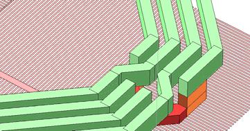

8 Effect of Balanced Ports Current Under a Patterned Ground What does intuition say about current direction? 8

9 Very Fine Detail of Current Under Fingers Effect of Finger Width Finger width makes little difference. Using solid anisotropic metal is OK. Important when ground shield is too fine for EM analysis. 9
10 Conclusion Current is NOT magnetically induced in the Si substrate under a spiral inductor. It is electrically induced. A patterned ground shield shorts out the electric field that would otherwise induce current in the substrate. Understanding the substrate current is a brand new field, still a LOT of research opportunity here. 10
Efficient Electromagnetic Analysis of Spiral Inductor Patterned Ground Shields
 Efficient Electromagnetic Analysis of Spiral Inductor Patterned Ground Shields James C. Rautio, James D. Merrill, and Michael J. Kobasa Sonnet Software, North Syracuse, NY, 13212, USA Abstract Patterned
Performance Enhancement For Spiral Indcutors, Design And Modeling
 Performance Enhancement For Spiral Indcutors, Design And Modeling Mohammad Hossein Nemati 16311 Sabanci University Final Report for Semiconductor Process course Introduction: How to practically improve
CITY UNIVERSITY OF HONG KONG
 CITY UNIVERSITY OF HONG KONG Modeling and Analysis of the Planar Spiral Inductor Including the Effect of Magnetic-Conductive Electromagnetic Shields Submitted to Department of Electronic Engineering in
Free EM Simulator Analyzes Spiral Inductor on Silicon
 Free EM Simulator Analyzes Spiral Inductor on Silicon by James C. Rautio Sonnet Software, Inc. 1020 Seventh North Street, Suite 210 Liverpool, NY 13088 (315)453-3096 info@sonnetusa.com http://www.sonnetusa.com
Using Sonnet EM Analysis with Cadence Virtuoso in RFIC Design. Sonnet Application Note: SAN-201B July 2011
 Using Sonnet EM Analysis with Cadence Virtuoso in RFIC Design Sonnet Application Note: SAN-201B July 2011 Description of Sonnet Suites Professional Sonnet Suites Professional is an industry leading full-wave
300 frequencies is calculated from electromagnetic analysis at only four frequencies. This entire analysis takes only four minutes.
 Electromagnetic Analysis Speeds RFID Design By Dr. James C. Rautio Sonnet Software, Inc. Liverpool, NY 13088 (315) 453-3096 info@sonnetusa.com http://www.sonnetusa.com Published in Microwaves & RF, February
INF 5490 RF MEMS. LN12: RF MEMS inductors. Spring 2011, Oddvar Søråsen Department of informatics, UoO
 INF 5490 RF MEMS LN12: RF MEMS inductors Spring 2011, Oddvar Søråsen Department of informatics, UoO 1 Today s lecture What is an inductor? MEMS -implemented inductors Modeling Different types of RF MEMS
Microwave Metrology -ECE 684 Spring Lab Exercise T: TRL Calibration and Probe-Based Measurement
 ab Exercise T: TR Calibration and Probe-Based Measurement In this project, you will measure the full phase and magnitude S parameters of several surface mounted components. You will then develop circuit
Chapter 2. Inductor Design for RFIC Applications
 Chapter 2 Inductor Design for RFIC Applications 2.1 Introduction A current carrying conductor generates magnetic field and a changing current generates changing magnetic field. According to Faraday s laws
BE. Electronic and Computer Engineering Final Year Project Report
 BE. Electronic and Computer Engineering Final Year Project Report Title: Development of electrical models for inductive coils used in wireless power systems Paul Burke 09453806 3 rd April 2013 Supervisor:
Transfer Functions in EMC Shielding Design
 Transfer Functions in EMC Shielding Design Transfer Functions Definition Overview of Theory Shielding Effectiveness Definition & Test Anomalies George Kunkel CEO, Spira Manufacturing Corporation www.spira-emi.com
EM Analysis of RFIC Transmission Lines
 EM Analysis of RFIC Transmission Lines Purpose of this document: In this document, we will discuss the analysis of single ended and differential on-chip transmission lines, the interpretation of results
Accurate Models for Spiral Resonators
 MITSUBISHI ELECTRIC RESEARCH LABORATORIES http://www.merl.com Accurate Models for Spiral Resonators Ellstein, D.; Wang, B.; Teo, K.H. TR1-89 October 1 Abstract Analytically-based circuit models for two
150Hz to 1MHz magnetic field coupling to a typical shielded cable above a ground plane configuration
 150Hz to 1MHz magnetic field coupling to a typical shielded cable above a ground plane configuration D. A. Weston Lowfreqcablecoupling.doc 7-9-2005 The data and information contained within this report
Equivalent Circuit Model Overview of Chip Spiral Inductors
 Equivalent Circuit Model Overview of Chip Spiral Inductors The applications of the chip Spiral Inductors have been widely used in telecommunication products as wireless LAN cards, Mobile Phone and so on.
PHYSICS WORKSHEET CLASS : XII. Topic: Alternating current
 PHYSICS WORKSHEET CLASS : XII Topic: Alternating current 1. What is mean by root mean square value of alternating current? 2. Distinguish between the terms effective value and peak value of an alternating
An Equivalent Circuit Model for On-chip Inductors with Gradual Changed Structure
 An Equivalent Circuit Model for On-chip Inductors with Gradual Changed Structure Xi Li 1, Zheng Ren 2, Yanling Shi 1 1 East China Normal University Shanghai 200241 People s Republic of China 2 Shanghai
S-Parameters Simulation
 S-Parameters Simulation of an RLC filter Description An RLC circuit is an electrical circuit formed of a number of resistors, inductors and capacitors. There are multiple applications for this type of
OPTIMIZED FRACTAL INDUCTOR FOR RF APPLICATIONS
 OPTIMIZED FRACTAL INDUCTOR FOR RF APPLICATIONS B. V. N. S. M. Nagesh Deevi and N. Bheema Rao 1 Department of Electronics and Communication Engineering, NIT-Warangal, India 2 Department of Electronics and
A Fundamental Approach for Design and Optimization of a Spiral Inductor
 Journal of Electrical Engineering 6 (2018) 256-260 doi: 10.17265/2328-2223/2018.05.002 D DAVID PUBLISHING A Fundamental Approach for Design and Optimization of a Spiral Inductor Frederick Ray I. Gomez
EE 521: Instrumentation and Measurements
 Aly El-Osery Electrical Engineering Department, New Mexico Tech Socorro, New Mexico, USA October 18, 2009 1 / 18 1 Sources of Coherent Interference Capacitive Coupling Inductive Coupling Ground Loops Power
Innovative Electrical Thermal Co-design of Ultra-high Q TPV-based 3D Inductors. Glass Packages
 2016 IEEE 66th Electronic Components and Technology Conference Innovative Electrical Thermal Co-design of Ultra-high Q TPV-based 3D Inductors in Glass Packages Min Suk Kim, Markondeya Raj Pulugurtha, Zihan
PRELIMINARIES. Generators and loads are connected together through transmission lines transporting electric power from one place to another.
 TRANSMISSION LINES PRELIMINARIES Generators and loads are connected together through transmission lines transporting electric power from one place to another. Transmission line must, therefore, take power
Design of a planar inductor for DC-DC converter on flexible foil applications
 Design of a planar inductor for DC-DC converter on flexible foil applications Jurica Kundrata, Adrijan Baric University of Zagreb, Faculty of Electrical Engineering and Computing Unska 3, 10000 Zagreb,
Magnetic induction with Cobra3
 Principle A magnetic field of variable frequency and varying strength is produced in a long coil. The voltages induced across thin coils which are pushed into the long coil are determined as a function
Accurate Electromagnetic Simulation and Measurement of Millimeter-wave Inductors in Bulk CMOS Technology
 Accurate Electromagnetic Simulation and Measurement of Millimeter-wave Inductors in Bulk CMOS Technology Michael Kraemer, Daniela Dragomirescu, Robert Plana To cite this version: Michael Kraemer, Daniela
Antennas 1. Antennas
 Antennas Antennas 1! Grading policy. " Weekly Homework 40%. " Midterm Exam 30%. " Project 30%.! Office hour: 3:10 ~ 4:00 pm, Monday.! Textbook: Warren L. Stutzman and Gary A. Thiele, Antenna Theory and
Electrical Engineering / Electromagnetics
 Electrical Engineering / Electromagnetics. Plot voltage versus time and current versus time for the circuit with the following substitutions: A. esistor B. Capacitor C. Inductor t = 0 A/B/C A. I t t B.
N-Port T-Networks and Topologically Symmetric Circuit Theory James C. Rautio, Fellow, IEEE
 IEEE TRANSACTIONS ON MICROWAVE THEORY AND TECHNIQUES, VOL. 58, NO. 4, APRIL 2010 705 N-Port T-Networks and Topologically Symmetric Circuit Theory James C. Rautio, Fellow, IEEE Abstract -port Pi-networks
Cell size and box size in Sonnet RFIC inductor analysis
 Cell size and box size in Sonnet RFIC inductor analysis Purpose of this document: This document describes the effect of some analysis settings in Sonnet: Influence of the cell size Influence of thick metal
Categorized by the type of core on which inductors are wound:
 Inductors Categorized by the type of core on which inductors are wound: air core and magnetic core. The magnetic core inductors can be subdivided depending on whether the core is open or closed. Equivalent
Challenges to Improving the Accuracy of High Frequency (120MHz) Test Systems
 Test Systems") Challenges to Improving the Accuracy of High Frequency (120MHz) Test Systems Applied Power Electronics Conference March 25 th, 2017 Tampa, USA Zoran Pavlovic, Santosh Kulkarni, Satya Kubendran, Cristina
Challenges to Improving the Accuracy of High Frequency (120MHz) Test Systems Applied Power Electronics Conference March 25 th, 2017 Tampa, USA Zoran Pavlovic, Santosh Kulkarni, Satya Kubendran, Cristina
Voltage-Versus-Speed Characteristic of a Wind Turbine Generator
 Exercise 1 Voltage-Versus-Speed Characteristic of a Wind Turbine Generator EXERCISE OBJECTIVE When you have completed this exercise, you will be familiar with the principle of electromagnetic induction.
Synthesis of Optimal On-Chip Baluns
 Synthesis of Optimal On-Chip Baluns Sharad Kapur, David E. Long and Robert C. Frye Integrand Software, Inc. Berkeley Heights, New Jersey Yu-Chia Chen, Ming-Hsiang Cho, Huai-Wen Chang, Jun-Hong Ou and Bigchoug
Electrical Theory 2 Lessons for Fall Semester:
 Electrical Theory 2 Lessons for Fall Semester: Lesson 1 Magnetism Lesson 2 Introduction to AC Theory Lesson 3 Lesson 4 Capacitance and Capacitive Reactance Lesson 5 Impedance and AC Circuits Lesson 6 AC
10 Safety earthing/grounding does not help EMC at RF
 1of 6 series Webinar #3 of 3, August 28, 2013 Grounding, Immunity, Overviews of Emissions and Immunity, and Crosstalk Contents of Webinar #3 Topics 1 through 9 were covered by the previous two webinars
Outcomes from this session
 Outcomes from this session At the end of this session you should be able to Understand what is meant by the term losses. Iron Losses There are three types of iron losses Eddy current losses Hysteresis
On-chip Inductors and Transformer
 On-chip Inductors and Transformer Applied Electronics Conference SP1.4 Supply on a Chip - PwrSoC Palm Springs, California 25 Feb 2010 James J. Wang Founder LLC 3131 E. Muirwood Drive Phoenix, Arizona 85048
On-Chip Spiral Inductors and On-Chip Spiral Transistors for Accurate Numerical Modeling
 Journal of Magnetics 23(1), 50-54 (2018) ISSN (Print) 1226-1750 ISSN (Online) 2233-6656 https://doi.org/10.4283/jmag.2018.23.1.050 On-Chip Spiral Inductors and On-Chip Spiral Transistors for Accurate Numerical
CH 1. Large coil. Small coil. red. Function generator GND CH 2. black GND
 Experiment 6 Electromagnetic Induction "Concepts without factual content are empty; sense data without concepts are blind... The understanding cannot see. The senses cannot think. By their union only can
Eddy Current Testing (ET) Technique
 Technique") Research Group Eddy Current Testing (ET) Technique Professor Pedro Vilaça * * Contacts: Address: Puumiehenkuja 3 (room 202), 02150 Espoo, Finland pedro.vilaca@aalto.fi October 2017 Contents Historical
Research Group Eddy Current Testing (ET) Technique Professor Pedro Vilaça * * Contacts: Address: Puumiehenkuja 3 (room 202), 02150 Espoo, Finland pedro.vilaca@aalto.fi October 2017 Contents Historical
EM Analysis of RFIC Inductors and Transformers. Dr.-Ing. Volker Mühlhaus Dr. Mühlhaus Consulting & Software GmbH, Witten
 EM Analysis of RFIC Inductors and Transformers Dr.-Ing. Volker Mühlhaus, Witten Do you love inductors? Image Kansas State University Inductors from the design kit tend to have the wrong value, optimized
EDDY CURRENT INSPECTION FOR DEEP CRACK DETECTION AROUND FASTENER HOLES IN AIRPLANE MULTI-LAYERED STRUCTURES
 EDDY CURRENT INSPECTION FOR DEEP CRACK DETECTION AROUND FASTENER HOLES IN AIRPLANE MULTI-LAYERED STRUCTURES Teodor Dogaru Albany Instruments Inc., Charlotte, NC tdogaru@hotmail.com Stuart T. Smith Center
EM Design of an Isolated Coplanar RF Cross for MEMS Switch Matrix Applications
 EM Design of an Isolated Coplanar RF Cross for MEMS Switch Matrix Applications W.Simon 1, A.Lauer 1, B.Schauwecker 2, A.Wien 1 1 IMST GmbH, Carl-Friedrich-Gauss-Str. 2, 47475 Kamp Lintfort, Germany; E-Mail:
Bakiss Hiyana binti Abu Bakar JKE, POLISAS BHAB
 1 Bakiss Hiyana binti Abu Bakar JKE, POLISAS 1. Explain AC circuit concept and their analysis using AC circuit law. 2. Apply the knowledge of AC circuit in solving problem related to AC electrical circuit.
Considerations in High-Speed High Performance Die-Package-Board Co-Design. Jenny Jiang Altera Packaging Department October 2014
 Considerations in High-Speed High Performance Die-Package-Board Co-Design Jenny Jiang Altera Packaging Department October 2014 Why Co-Design? Complex Multi-Layer BGA Package Horizontal and vertical design
2015 ELECTRICAL SCIENCE
 Summer 2015 ELECTRICAL SCIENCE TIME: THREE HOURS Maximum Marks : 100 Answer five questions, taking ANY TWO from GROUP A, ANY TWO from GROUP B and from GROUP C. All parts of a question (a,b,etc) should
SHIELDING EFFECTIVENESS
 SHIELDING Electronic devices are commonly packaged in a conducting enclosure (shield) in order to (1) prevent the electronic devices inside the shield from radiating emissions efficiently and/or (2) prevent
Common Impedance Shield Coupling
 Common Impedance Shield Coupling When a coaxial cable is used at low frequencies and the shield is grounded at both ends, V R I IN S S The shield serves two functions: 1. the return conductor for the signal;
Table of Contents. Table of Figures. Table of Tables
 Abstract The aim of this report is to investigate and test a transformer and check if it is good to use by doing the following tests continuity test, insulation test, polarity test, open circuit test,
FEM SIMULATION FOR DESIGN AND EVALUATION OF AN EDDY CURRENT MICROSENSOR
 FEM SIMULATION FOR DESIGN AND EVALUATION OF AN EDDY CURRENT MICROSENSOR Heri Iswahjudi and Hans H. Gatzen Institute for Microtechnology Hanover University Callinstrasse 30A, 30167 Hanover Germany E-mail:
When I first started doing microwave
 James C. Rautio When I first started doing microwave design, the pocket calculator was just starting to replace the slide rule and the Smith chart was king (Figure ). After a few years, I moved on to developing
Design and optimization of integrated transmission lines on scaled CMOS technologies
 Design and optimization of integrated transmission lines on scaled CMOS technologies F. Vecchi 1,2, M. Repossi 3, W. Eyssa 1,2, P. Arcioni 1, F. Svelto 1 1 Dipartimento di Elettronica, Università di Pavia,
Chapter Moving Charges and Magnetism
 100 Chapter Moving Charges and Magnetism 1. The power factor of an AC circuit having resistance (R) and inductance (L) connected in series and an angular velocity ω is [2013] 2. [2002] zero RvB vbl/r vbl
GLOSSARY OF TERMS FLUX DENSITY:
 ADSL: Asymmetrical Digital Subscriber Line. Technology used to transmit/receive data and audio using the pair copper telephone lines with speed up to 8 Mbps. AMBIENT TEMPERATURE: The temperature surrounding
2052 IEEE TRANSACTIONS ON POWER ELECTRONICS, VOL. 23, NO. 4, JULY 2008
 2052 IEEE TRANSACTIONS ON POWER ELECTRONICS, VOL. 23, NO. 4, JULY 2008 Extended Theory on the Inductance Calculation of Planar Spiral Windings Including the Effect of Double-Layer Electromagnetic Shield
Signal Integrity Design of TSV-Based 3D IC
 Signal Integrity Design of TSV-Based 3D IC October 24, 21 Joungho Kim at KAIST joungho@ee.kaist.ac.kr http://tera.kaist.ac.kr 1 Contents 1) Driving Forces of TSV based 3D IC 2) Signal Integrity Issues
( ). (9.3) 9. EXPERIMENT E9: THE RLC CIRCUIT OBJECTIVES
. (9.3) 9. EXPERIMENT E9: THE RLC CIRCUIT OBJECTIVES") 9. EXPERIMENT E9: THE RLC CIRCUIT OBJECTIVES In this experiment, you will measure the electric current, voltage, reactance, impedance, and understand the resonance phenomenon in an alternating-current
9. EXPERIMENT E9: THE RLC CIRCUIT OBJECTIVES In this experiment, you will measure the electric current, voltage, reactance, impedance, and understand the resonance phenomenon in an alternating-current
Embedded inductor design and electromagnetic compatibility issues
 Embedded inductor design and electromagnetic compatibility issues J. Kundrata, D.Bandic and A. Baric University of Zagreb IMOLA Final Workshop Slide 1/22 Outline Design challenges Planar inductor designs
Chapter 25. Electromagnetic Induction
 Lecture 28 Chapter 25 Electromagnetic Induction Electromagnetic Induction Voltage is induced (produced) when the magnetic field changes near a stationary conducting loop or the conductor moves through
Inductors & Resonance
 Inductors & Resonance The Inductor This figure shows a conductor carrying a current. A magnetic field is set up around the conductor as concentric circles. If a coil of wire has a current flowing through
VLSI is scaling faster than number of interface pins
 High Speed Digital Signals Why Study High Speed Digital Signals Speeds of processors and signaling Doubled with last few years Already at 1-3 GHz microprocessors Early stages of terahertz Higher speeds
An explanation for the magic low frequency magnetic field shielding effectiveness of thin conductive foil with a relative permeability of 1
 An explanation for the magic low frequency magnetic field shielding effectiveness of thin conductive foil with a relative permeability of 1 D.A. Weston K McDougall (magicse.r&d.doc) 31-7-2006 The data
The SI unit of inductance is the henry, defined as:
 Inductors A coil of wire, or solenoid, can be used in a circuit to store energy in the magnetic field. We define the inductance of a solenoid having N turns, length l and cross-section area A as: The SI
Today I would like to present a short introduction to microstrip cross-coupled filter design. I will be using Sonnet em to analyze my planar circuit.
 Today I would like to present a short introduction to microstrip cross-coupled filter design. I will be using Sonnet em to analyze my planar circuit. And I will be using our optimizer, EQR_OPT_MWO, in
Chapter 33. Alternating Current Circuits
 Chapter 33 Alternating Current Circuits Alternating Current Circuits Electrical appliances in the house use alternating current (AC) circuits. If an AC source applies an alternating voltage to a series
Investigation of a Voltage Probe in Microstrip Technology
 Investigation of a Voltage Probe in Microstrip Technology (Specifically in 7-tesla MRI System) By : Mona ParsaMoghadam Supervisor : Prof. Dr. Ing- Klaus Solbach April 2015 Introduction - Thesis work scope
Designers Series XIII
 Designers Series XIII 1 We have had many requests over the last few years to cover magnetics design in our magazine. It is a topic that we focus on for two full days in our design workshops, and it has
(c) In the process of part (b), must energy be supplied to the electron, or is energy released?
 In the process of part (b), must energy be supplied to the electron, or is energy released?") (1) A capacitor, as shown, has plates of dimensions 10a by 10a, and plate separation a. The field inside is uniform, and has magnitude 120 N/C. The constant a equals 4.5 cm. (a) What amount of charge is
(1) A capacitor, as shown, has plates of dimensions 10a by 10a, and plate separation a. The field inside is uniform, and has magnitude 120 N/C. The constant a equals 4.5 cm. (a) What amount of charge is
Look over Chapter 31 sections 1-4, 6, 8, 9, 10, 11 Examples 1-8. Look over Chapter 21 sections Examples PHYS 2212 PHYS 1112
 PHYS 2212 Look over Chapter 31 sections 1-4, 6, 8, 9, 10, 11 Examples 1-8 PHYS 1112 Look over Chapter 21 sections 11-14 Examples 16-18 Good Things To Know 1) How AC generators work. 2) How to find the
CHAPTER 5 PRINTED FLARED DIPOLE ANTENNA
 CHAPTER 5 PRINTED FLARED DIPOLE ANTENNA 5.1 INTRODUCTION This chapter deals with the design of L-band printed dipole antenna (operating frequency of 1060 MHz). A study is carried out to obtain 40 % impedance
DEEP FLAW DETECTION WITH GIANT MAGNETORESISTIVE (GMR) BASED SELF-NULLING PROBE
 BASED SELF-NULLING PROBE") DEEP FLAW DETECTION WITH GIANT MAGNETORESISTIVE (GMR) BASED SELF-NULLING PROBE Buzz Wincheski and Min Namkung NASA Langley Research Center Hampton, VA 23681 INTRODUCTION The use of giant magnetoresistive
DEEP FLAW DETECTION WITH GIANT MAGNETORESISTIVE (GMR) BASED SELF-NULLING PROBE Buzz Wincheski and Min Namkung NASA Langley Research Center Hampton, VA 23681 INTRODUCTION The use of giant magnetoresistive
Flexible PCB-Based Eddy Current Array Probes for the Inspection of Turbine Components
 Flexible PCB-Based Eddy Current Array Probes for the Inspection of Turbine Components Andre Lamarre - OlympusNDT-Quebec City Canada Benoit Lepage - OlympusNDT-Quebec City-Canada Tommy Bourgelas - OlympusNDT-Quebec
Understanding the Unintended Antenna Behavior of a Product
 Understanding the Unintended Antenna Behavior of a Product Colin E. Brench Southwest Research Institute Electromagnetic Compatibility Research and Testing colin.brench@swri.org Radiating System Source
RF simulations with COMSOL
 RF simulations with COMSOL ICPS 217 Politecnico di Torino Aug. 1 th, 217 Gabriele Rosati gabriele.rosati@comsol.com 3 37.93.8 Copyright 217 COMSOL. Any of the images, text, and equations here may be copied
Experiment 9: AC circuits
 Experiment 9: AC circuits Nate Saffold nas2173@columbia.edu Office Hour: Mondays, 5:30PM-6:30PM @ Pupin 1216 INTRO TO EXPERIMENTAL PHYS-LAB 1493/1494/2699 Introduction Last week (RC circuit): This week:
Reduction stray loss on transformer tank wall with optimized widthwise electromagnetic shunts
 Reduction stray loss on transformer tank wall with optimized widthwise electromagnetic shunts Atabak Najafi 1, Okan Ozgonenel, Unal Kurt 3 1 Electrical and Electronic Engineering, Ondokuz Mayis University,
Internal Model of X2Y Chip Technology
 Internal Model of X2Y Chip Technology Summary At high frequencies, traditional discrete components are significantly limited in performance by their parasitics, which are inherent in the design. For example,
ISSCC 2004 / SESSION 21/ 21.1
 ISSCC 2004 / SESSION 21/ 21.1 21.1 Circular-Geometry Oscillators R. Aparicio, A. Hajimiri California Institute of Technology, Pasadena, CA Demand for faster data rates in wireline and wireless markets
Standing waves. Consider a string with 2 waves of equal amplitude moving in opposite directions. or, if you prefer cos T
 Waves 2 1. Standing waves 2. Transverse waves in nature: electromagnetic radiation 3. Polarisation 4. Dispersion 5. Information transfer and wave packets 6. Group velocity 1 Standing waves Consider a string
EMDS for ADS Momentum
 EMDS for ADS Momentum ADS User Group Meeting 2009, Böblingen, Germany Prof. Dr.-Ing. Frank Gustrau Gustrau, Dortmund User Group Meeting 2009-1 Univ. of Applied Sciences and Arts (FH Dortmund) Presentation
Kiat T. Ng, Behzad Rejaei, # Mehmet Soyuer and Joachim N. Burghartz
 Kiat T. Ng, Behzad Rejaei, # Mehmet Soyuer and Joachim N. Burghartz Microwave Components Group, Laboratory of Electronic Components, Technology, and Materials (ECTM), DIMES, Delft University of Technology,
AC Circuit. What is alternating current? What is an AC circuit?
 Chapter 21 Alternating Current Circuits and Electromagnetic Waves 1. Alternating Current 2. Resistor in an AC circuit 3. Capacitor in an AC circuit 4. Inductor in an AC circuit 5. RLC series circuit 6.
Goals. Introduction. To understand the use of root mean square (rms) voltages and currents.
 voltages and currents.") Lab 10. AC Circuits Goals To show that AC voltages cannot generally be added without accounting for their phase relationships. That is, one must account for how they vary in time with respect to one another.
Lab 10. AC Circuits Goals To show that AC voltages cannot generally be added without accounting for their phase relationships. That is, one must account for how they vary in time with respect to one another.
MPC 5534 Case study. E. Sicard (1), B. Vrignon (2) Toulouse France. Contact : web site :
, B. Vrignon (2) Toulouse France. Contact : web site :") MPC 5534 Case study E. Sicard (1), B. Vrignon (2) (1) INSA-GEI, 135 Av de Rangueil 31077 Toulouse France (2) Freescale Semiconductors, Toulouse, France Contact : etienne.sicard@insa-toulouse.fr web site
MPC 5534 Case study E. Sicard (1), B. Vrignon (2) (1) INSA-GEI, 135 Av de Rangueil 31077 Toulouse France (2) Freescale Semiconductors, Toulouse, France Contact : etienne.sicard@insa-toulouse.fr web site
11 Myths of EMI/EMC ORBEL.COM. Exploring common misconceptions and clarifying them. MYTH #1: EMI/EMC is black magic.
 11 Myths of EMI/EMC Exploring common misconceptions and clarifying them By Ed Nakauchi, Technical Consultant, Orbel Corporation What is a myth? A myth is defined as a popular belief or tradition that has
ECE 145A and 218A. Transmission-line properties, impedance-matching exercises
 ECE 145A and 218A. Transmission-line properties, impedance-matching exercises Problem #1 This is a circuit file to study a transmission line. The 2 resistors are included to allow easy disconnection of
DISCUSSION OF FUNDAMENTALS
 Unit 4 AC s UNIT OBJECTIVE After completing this unit, you will be able to demonstrate and explain the operation of ac induction motors using the Squirrel-Cage module and the Capacitor-Start Motor module.
Through-Silicon-Via Inductor: Is it Real or Just A Fantasy?
 Through-Silicon-Via Inductor: Is it Real or Just A Fantasy? Umamaheswara Rao Tida 1 Cheng Zhuo 2 Yiyu Shi 1 1 ECE Department, Missouri University of Science and Technology 2 Intel Research, Hillsboro Outline
Alternating Current. Slide 1 / 69. Slide 2 / 69. Slide 3 / 69. Topics to be covered. Sources of Alternating EMF. Sources of alternating EMF
 Slide 1 / 69 lternating urrent Sources of alternating EMF Transformers ircuits and Impedance Topics to be covered Slide 2 / 69 LR Series ircuits Resonance in ircuit Oscillations Sources of lternating EMF
Alternating Current. Slide 2 / 69. Slide 1 / 69. Slide 3 / 69. Slide 4 / 69. Slide 6 / 69. Slide 5 / 69. Topics to be covered
 Slide 1 / 69 lternating urrent Sources of alternating EMF ircuits and Impedance Slide 2 / 69 Topics to be covered LR Series ircuits Resonance in ircuit Oscillations Slide 3 / 69 Sources of lternating EMF
West Coast Magnetics. Advancing Power Electronics FOIL WINDINGS FOR SMPS INDUCTORS AND TRANSFORMERS. Weyman Lundquist, CEO and Engineering Manager
 1 West Coast Magnetics Advancing Power Electronics FOIL WINDINGS FOR SMPS INDUCTORS AND TRANSFORMERS Weyman Lundquist, CEO and Engineering Manager TYPES OF WINDINGS 2 Solid wire Lowest cost Low DC resistance
Square Planar Spiral Inductor High Frequency Field and Parameters Analysis
 Volume 56, Number 5, 2015 191 Square Planar Spiral Inductor High Frequency Field and Parameters Analysis Claudia Păcurar, Vasile Țopa, Adina Răcășan, Călin Munteanu, Claudia Constantinescu, Mihaela Vid
Simulation and Design of a Tunable Patch Antenna
 Simulation and Design of a Tunable Patch Antenna Benjamin D. Horwath and Talal Al-Attar Department of Electrical Engineering, Center for Analog Design and Research Santa Clara University, Santa Clara,
1 FUNDAMENTAL CONCEPTS What is Noise Coupling 1
 Contents 1 FUNDAMENTAL CONCEPTS 1 1.1 What is Noise Coupling 1 1.2 Resistance 3 1.2.1 Resistivity and Resistance 3 1.2.2 Wire Resistance 4 1.2.3 Sheet Resistance 5 1.2.4 Skin Effect 6 1.2.5 Resistance
DETERMINING CELL SIZE IN EMSIGHT
 ............................ INTRODUCTION..... Cell size definition is probably the most misunderstood part of an EMSight analysis. Often, experience and intuition determine cell sizes for experienced
Improvement of the Quality Factor of RF Integrated Inductors by Layout Optimization
 76 IEEE TRANSACTIONS ON MICROWAVE THEORY AND TECHNIQUES, VOL. 48, NO. 1, JANUARY 2000 Improvement of the Quality Factor of RF Integrated Inductors by Layout Optimization José M. López-Villegas, Member,
Exercise 9. Electromagnetism and Inductors EXERCISE OBJECTIVE DISCUSSION OUTLINE DISCUSSION. Magnetism, magnets, and magnetic field
 Exercise 9 Electromagnetism and Inductors EXERCISE OBJECTIVE When you have completed this exercise, you will be familiar with the concepts of magnetism, magnets, and magnetic field, as well as electromagnetism
EVALUATION OF THE NEAR-FIELD INJECTION METHOD AT INTEGRATED CIRCUIT LEVEL
 1 EVALUATION OF THE NEAR-FIELD INJECTION METHOD AT INTEGRATED CIRCUIT LEVEL A. Boyer 1,2, B. Vrignon 3, J. Shepherd 3, M. Cavarroc 1,2 1 CNRS, LAAS, 7 avenue du colonel Roche, F-31400 Toulouse, France
In this lecture. Electromagnetism. Electromagnetism. Oersted s Experiment. Electricity & magnetism are different aspects of the same basic phenomenon:
 In this lecture Electromagnetism Electromagnetic Effect Electromagnets Electromechanical Devices Transformers Electromagnetic Effect Electricity & magnetism are different aspects of the same basic phenomenon: