Common Impedance Shield Coupling
|
|
|
- Laurel Lawson
- 5 years ago
- Views:
Transcription

1 Common Impedance Shield Coupling When a coaxial cable is used at low frequencies and the shield is grounded at both ends, V R I IN S S The shield serves two functions: 1. the return conductor for the signal; 2. a shield and carries the induced noise current. JHLin, EMC; Cabling 1
2 Common Impedance Shield Coupling A remedy: using a three-conductor cable (e.g., a shielded twisted pair). CISC is often a problem in consumer audio systems that use unbalanced interconnection, which usually consists of a cable with a center conductor and a shield terminated in a phono plug. Remedies: R S or a balanced interconnection and a shielded twist pair. JHLin, EMC; Cabling 2
3 Common Impedance Shield Coupling Even if the shield is grounded at only one end, noise currents may still flow in the shield because of EM field coupling --- SCIN (shield current induced noise) This problem does not occur at high frequencies, because as the result of skin effect, a coaxial cable actually contains three isolated conductors. JHLin, EMC; Cabling 3

4 Experimental Data Test setup 50 khz > 5 times the shield cutoff frequency JHLin, EMC; Cabling 4


5 Experimental Data Circuits are grounded at both ends. JHLin, EMC; Cabling 5


6 Experimental Data Circuits are grounded at one end only. It is almost always better to connect the shield and the signal conductors together at just one point. That point should be such that noise current from the shield does not have to flow down the signal conductor to get to the ground. JHLin, EMC; Cabling 6


7 Example of Selective Shielding The shielded loop antenna is an example where E is selectively shielded, whereas H is unaffected. Such an antenna is useful in radio direction finders and as a magnetic field probe for precompliance EMC measurements. It can also decrease the antenna noise pickup in broadcast receivers. The latter effect is significant because most local noise sources generate a predominantly electric field. Vm 2 f BAcos Vm 0 V m 2 f BAcos V c 2 AE cos Vc 0 Vc 0 JHLin, EMC; Cabling 7
8 Shield Transfer Impedance A means of measuring the shielding effectiveness of cable shields. 1 dv ZT, where V is the open circuit voltage IS d developed between the center conductor and the shield. The smaller the transfer impedance, the more effective the shielding. At low frequencies, the transfer impedance is equal to the dc resistance of the shield. At higher frequencies (above 1 MHz for typical cables), because of the skin effect. Z T JHLin, EMC; Cabling 8


9 Shield Transfer Impedance JHLin, EMC; Cabling 9

10 Coaxial Cable vs. Twisted Pair Ethernet and HDMI: Less C and more tightly and uniformly twisted Twisted pair cables do not have as uniform as coaxial cables. Bonded twisted pair: more uniform, immune to noise, much less radiation. A twisted pair cable is inherently a balanced structure and effectively rejects noise. For example, Cat 5 and 6 Ethernet cables. JHLin, EMC; Cabling 10 Z 0 Z 0

11 Coaxial Cable vs. Twisted Pair Cat 5e (125 MHz), Cat 6 (250 MHz), Cat 7 (600 MHz). Coaxial cables have more uniform, lower losses. A double-shielded, or triaxial, cable can eliminate the noise voltage produced by the shield resistance. But it is expensive and awkward to use. Z 0 A coaxial cable behaves better at high frequencies. A STP has characteristics similar to a triaxial cable. A UTP, unless its terminations are balanced, not good at capacitive pickup protection, but very good for protection against H pickup. UTP JHLin, EMC; Cabling 11
12 Coaxial Cable vs. Twisted Pair When terminating a twisted pair, do not untwist the conductors any more than necessary to make the termination. Twisted pair effective in reducing H coupling when 1. the signal must flow equally and in opposite directions on the two conductors; 2. the pitch of the twist < 1/20 of at the frequency of concern. (500 MHz a twist/inch) JHLin, EMC; Cabling 12
13 Braided Shields The advantage of braid is flexibility, durability, strength, and long flex life. Braided shields usually provide just slightly reduced E shielding (except at UHF frequencies) but greatly reduced H shielding. The reason is that braid distorts the uniformity of the longitudinal shield current. JHLin, EMC; Cabling 13


14 Braided Shields Loose-weave braid provides more flexibility. A tighter weave braid provides better shielding and less flexibility. For the best shielding, the braid should provide at least 95% coverage. JHLin, EMC; Cabling 14
15 Spiral Shields A spiral shield is used on cables for one of 3 reasons: 1. reduced manufacturing cost; 2. ease of termination; 3. increased flexibility. The shield current follows the spiral JHLin, EMC; Cabling 15

16 Spiral Shields I L behaves the same as the shield current does on a solid, homogeneous, shielded cable and produces a circular H external to the cable. The longitudinal H increases the shield inductance. Braided shield cables have better high-f performance than spiral shield cables. Z T that results from the circular component of the shield current increases with f. as f Z T larger, the larger. Z T above about 100 khz. The JHLin, EMC; Cabling 16


17 Spiral Shields Spiral shields are used at audio frequencies. JHLin, EMC; Cabling 17


18 Shield Terminations Most shielded cable problems are the result of improper shield termination. Requirements of a proper shield termination: 1. Termination at the proper end, or ends, and to the proper point or points. 2. A very low impedance termination connection. 3. A 360 contact with the shield. Pigtails The shield should be terminated uniformly. BNC connectors. 18


19 Shield Terminations UHF connectors Type-N connectors JHLin, EMC; Cabling 19


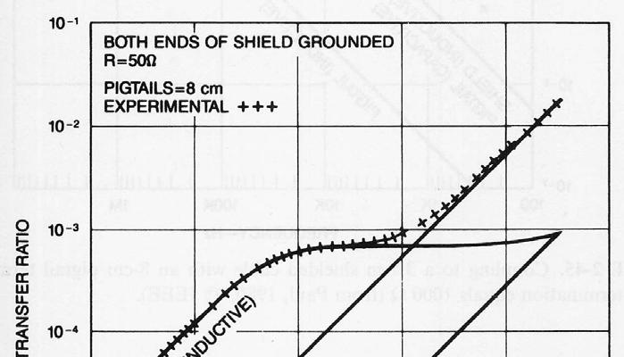
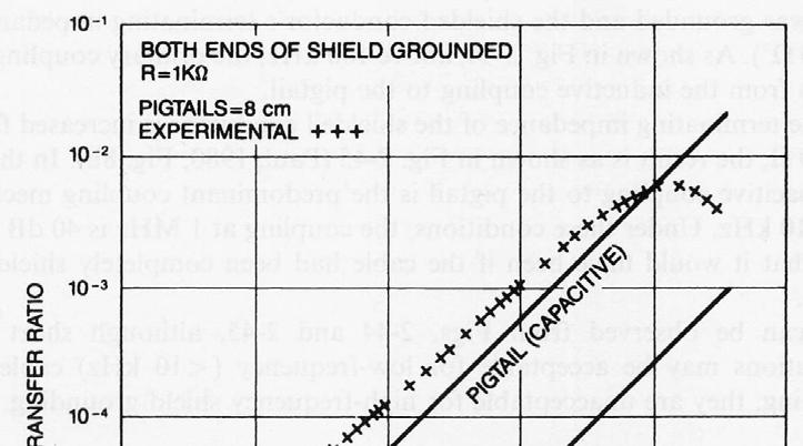
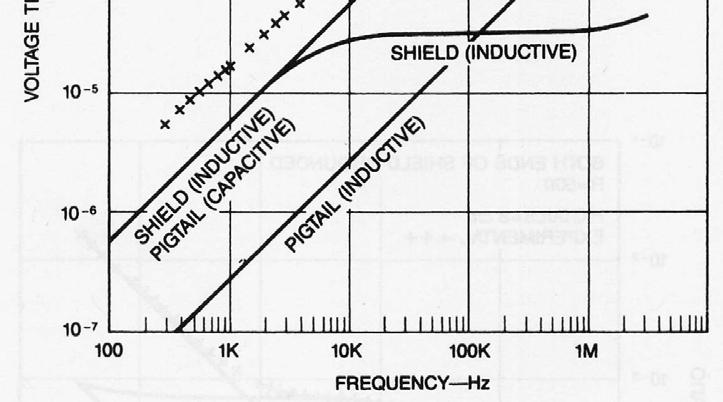
20 Shield Terminations A female XLR connector with spring fingers. Without a connector, still providing a 360 contact of the shield. The use of a pigtail termination whose length is only a small fraction of the total cable length can have a significant effect on the noise coupling to the cable at frequencies above 100 khz. Coupling to a 3.7-m shielded cable with an 8-cm pigtail termination. JHLin, EMC; Cabling 20
21 Shield Terminations JHLin, EMC; Cabling 21
22 Shield Terminations Grounding of Cable Shields Where should the shield be terminated? It depends! 1. Low-frequency cable shield grounding 2. High-frequency cable shield grounding 3. Hybrid-frequency cable shield grounding 4. Double shielded cable grounding JHLin, EMC; Cabling 22
150Hz to 1MHz magnetic field coupling to a typical shielded cable above a ground plane configuration
 150Hz to 1MHz magnetic field coupling to a typical shielded cable above a ground plane configuration D. A. Weston Lowfreqcablecoupling.doc 7-9-2005 The data and information contained within this report
EFFECT OF SHIELDING ON CABLE RF INGRESS MEASUREMENTS LARRY COHEN
 EFFECT OF SHIELDING ON CABLE RF INGRESS MEASUREMENTS LARRY COHEN OVERVIEW Purpose: Examine the common-mode and differential RF ingress levels of 4-pair UTP, F/UTP, and F/FTP cables at an (RJ45) MDI port
Chapter 12: Transmission Lines. EET-223: RF Communication Circuits Walter Lara
 Chapter 12: Transmission Lines EET-223: RF Communication Circuits Walter Lara Introduction A transmission line can be defined as the conductive connections between system elements that carry signal power.
Methods for Reducing Interference in Instrumentation
 by Kenneth A. Kuhn May 23, 1988, rev Feb. 3, 2008 Introduction This note deals with methods of connecting signals and correct use of shielding to reduce the pickup of undesired signals. Interference can
Use and abuse of screened cables
 December 2016 Use and abuse of screened cables Tim Williams Elmac Services 1 of 21 Outline How does a screened cable work? electric fields, magnetic fields, low versus high frequency Types of screen Transfer
Conduit measured transfer impedance and shielding effectiveness (typically achieved in the RS103 and CS114 tests)
") Conduit measured transfer impedance and shielding effectiveness (typically achieved in the RS3 and CS4 tests) D. A. Weston K. McDougall conduitse.doc 5-2-27 The data and information contained within this
Conduit measured transfer impedance and shielding effectiveness (typically achieved in the RS3 and CS4 tests) D. A. Weston K. McDougall conduitse.doc 5-2-27 The data and information contained within this
Setting up High Gain Detector Electronics for TCSPC
 Becker & Hickl GmbH Sept. 2000 higain1.doc Nahmitzer Damm 30 12277 Berlin Tel. +49 / 30 / 787 56 32 Fax. +49 / 30 / 787 57 34 email: info@becker-hickl.de http://www.becker-hickl.de Setting up High Gain
Signal and Noise Measurement Techniques Using Magnetic Field Probes
 Signal and Noise Measurement Techniques Using Magnetic Field Probes Abstract: Magnetic loops have long been used by EMC personnel to sniff out sources of emissions in circuits and equipment. Additional
Chapter 12 Digital Circuit Radiation. Electromagnetic Compatibility Engineering. by Henry W. Ott
 Chapter 12 Digital Circuit Radiation Electromagnetic Compatibility Engineering by Henry W. Ott Forward Emission control should be treated as a design problem from the start, it should receive the necessary
MEASUREMENTS OF COUPLING THROUGH BRAIDED SHIELD VIA NEW CONDUCTED IMMUNITY TECH- NIQUE
 Progress In Electromagnetics Research C, Vol. 11, 61 68, 2009 MEASUREMENTS OF COUPLING THROUGH BRAIDED SHIELD VIA NEW CONDUCTED IMMUNITY TECH- NIQUE M. Ghassempouri College of Electrical Engineering Iran
Designing external cabling for low EMI radiation A similar article was published in the December, 2004 issue of Planet Analog.
 HFTA-13.0 Rev.2; 05/08 Designing external cabling for low EMI radiation A similar article was published in the December, 2004 issue of Planet Analog. AVAILABLE Designing external cabling for low EMI radiation
Objectives of transmission lines
 Introduction to Transmission Lines Applications Telephone Cable TV (CATV, or Community Antenna Television) Broadband network High frequency (RF) circuits, e.g., circuit board, RF circuits, etc. Microwave
Dielectric Material. Cable Type
 UTP Video Cables West Penn Wire/CDT introduces its new line of UTP security cables,v/cat. The V/CAT ( Video over Category 5E) is designed for the video over UTP applications. The cables are constructed
Device Interconnection
 Device Interconnection An important, if less than glamorous, aspect of audio signal handling is the connection of one device to another. Of course, a primary concern is the matching of signal levels and
Flexible AC current probes
 Flexible AC current probes Making use of the principle of Rogowski coils, the MiniFLEX models are flexible sensors offering a wide dynamic range for measuring AC intensities and viewing high-speed current
Categorized by the type of core on which inductors are wound:
 Inductors Categorized by the type of core on which inductors are wound: air core and magnetic core. The magnetic core inductors can be subdivided depending on whether the core is open or closed. Equivalent
Cables and Interconnects
 Cables and Interconnects CinemaSource, 18 Denbow Rd., Durham, NH 03824 cinemasource.com 800-483-9778 CinemaSource Technical Bulletins. Copyright 2002 by CinemaSource, Inc. All rights reserved. Printed
ECE 528 Understanding Power Quality
 ECE 528 Understanding Power Quality http://www.ece.uidaho.edu/ee/power/ece528/ Paul Ortmann portmann@uidaho.edu 208-733-7972 (voice) Lecture 41 1 Today Wiring for communications Decibels Coupling Avoiding
Line Level Cables in the Automotive Environment
 Line Level Cables in the Automotive Environment Dan Wiggins Adire Audio http://www.adireaudio.com The automotive environment can be a very difficult one for line level cables (RCA cables). High voltage
Verifying Simulation Results with Measurements. Scott Piper General Motors
 Verifying Simulation Results with Measurements Scott Piper General Motors EM Simulation Software Can be easy to justify the purchase of software packages even costing tens of thousands of dollars Upper
SCIN. Shield Current Induced Noise. Causes and Solutions. Random Thoughts from Chicago
 Random Thoughts from Chicago SCIN Shield Current Induced Noise by Jim Brown Causes and Solutions My last two columns have focused on pin 1 problems as an open door for RF into audio equipment. But RF can
87415A microwave system amplifier A microwave. system amplifier A microwave system amplifier A microwave.
 20 Amplifiers 83020A microwave 875A microwave 8308A microwave 8307A microwave 83006A microwave 8705C preamplifier 8705B preamplifier 83050/5A microwave The Agilent 83006/07/08/020/050/05A test s offer
Coupling- / Decoupling Network. 150 khz 300 MHz. 150 khz 230 MHz. 10 khz 230 MHz. IEC and CISPR 15 / CISPR 22 IEC
 Coupling- / Decoupling Network 150 khz 300 MHz IEC 61000-4 - 6 and CISPR 15 / CISPR 22 150 khz 230 MHz IEC 61000-4 - 6 10 khz 230 MHz IEC 61000-4 - 6 and IEC 61326-3 - 2 and NE-21 Coupling and decoupling
EMC Near-field Probes + Wideband Amplifier
 1 Introduction The H20, H10, H5 and E5 are magnetic field (H) and electric field (E) probes for radiated emissions EMC precompliance measurements. The probes are used in the near field of sources of electromagnetic
CONNECTING THE PROBE TO THE TEST INSTRUMENT
 2SHUDWLRQ 2SHUDWLRQ Caution The input circuits in the AP034 Active Differential Probe incorporate components that protect the probe from damage resulting from electrostatic discharge (ESD). Keep in mind
Ground Loop Noise and Opto-Isolation
 Ground Loop Noise and Opto-Isolation Outline 1. Ground Loops 2. Opto-Isolators 3. Mixed signal circuits: separating analog and digital circuitry. Ground Loops A ground ground loop loop occurs occurs when
DATA TRANSMISSION. ermtiong. ermtiong
 DATA TRANSMISSION Analog Transmission Analog signal transmitted without regard to content May be analog or digital data Attenuated over distance Use amplifiers to boost signal Also amplifies noise DATA
Physical Test Setup for Impulse Noise Testing
 Physical Test Setup for Impulse Noise Testing Larry Cohen Overview Purpose: Use measurement results for the EM coupling (Campbell) clamp to determine a stable physical test setup for impulse noise testing.
Debugging EMI Using a Digital Oscilloscope. Dave Rishavy Product Manager - Oscilloscopes
 Debugging EMI Using a Digital Oscilloscope Dave Rishavy Product Manager - Oscilloscopes 06/2009 Nov 2010 Fundamentals Scope Seminar of DSOs Signal Fidelity 1 1 1 Debugging EMI Using a Digital Oscilloscope
User s Manual for Integrator Short Pulse ISP16 10JUN2016
 User s Manual for Integrator Short Pulse ISP16 10JUN2016 Specifications Exceeding any of the Maximum Ratings and/or failing to follow any of the Warnings and/or Operating Instructions may result in damage
Archived 3/18/10 USER MANUAL EMCO MODEL 3141 BICONILOG TM LOG-PERIODIC / T BOW-TIE ANTENNA Rev A 01/97
 USER MANUAL EMCO MODEL 3141 BICONILOG TM LOG-PERIODIC / T BOW-TIE ANTENNA 399236 Rev A 01/97 GENERAL DESCRIPTION The EMCO Model 3141 is the latest evolution in the popular bow-tie/log periodic combination
Trees, vegetation, buildings etc.
 EMC Measurements Test Site Locations Open Area (Field) Test Site Obstruction Free Trees, vegetation, buildings etc. Chamber or Screened Room Smaller Equipments Attenuate external fields (about 100dB) External
Internal Model of X2Y Chip Technology
 Internal Model of X2Y Chip Technology Summary At high frequencies, traditional discrete components are significantly limited in performance by their parasitics, which are inherent in the design. For example,
Experiment 5: Grounding and Shielding
 Experiment 5: Grounding and Shielding Power System Hot (Red) Neutral (White) Hot (Black) 115V 115V 230V Ground (Green) Service Entrance Load Enclosure Figure 1 Typical residential or commercial AC power
EE 241 Experiment #4: USE OF BASIC ELECTRONIC MEASURING INSTRUMENTS, Part III 1
 EE 241 Experiment #4: USE OF BASIC ELECTRONIC MEASURING INSTRUMENTS, Part III 1 PURPOSE: To become familiar with more of the instruments in the laboratory. To become aware of operating limitations of input
INSTRUCTION MANUAL TRI-PLATE LINE MODEL EM-7310
 INSTRUCTION MANUAL TRI-PLATE LINE MODEL EM-7310 INSTRUCTION MANUAL THIS INSTRUCTION MANUAL AND ITS ASSOCIATED INFORMATION IS PRO- PRIETARY. UNAUTHORIZED REPRO- DUCTION IS FORBIDDEN. 1998 ELECTRO-METRICS
10 Safety earthing/grounding does not help EMC at RF
 1of 6 series Webinar #3 of 3, August 28, 2013 Grounding, Immunity, Overviews of Emissions and Immunity, and Crosstalk Contents of Webinar #3 Topics 1 through 9 were covered by the previous two webinars
G019.A (4/99) UNDERSTANDING COMMON MODE NOISE
 UNDERSTANDING COMMON MODE NOISE") UNDERSTANDING COMMON MODE NOISE PAGE 2 OF 7 TABLE OF CONTENTS 1 INTRODUCTION 2 DIFFERENTIAL MODE AND COMMON MODE SIGNALS 2.1 Differential Mode signals 2.2 Common Mode signals 3 DIFFERENTIAL AND COMMON
UNDERSTANDING COMMON MODE NOISE PAGE 2 OF 7 TABLE OF CONTENTS 1 INTRODUCTION 2 DIFFERENTIAL MODE AND COMMON MODE SIGNALS 2.1 Differential Mode signals 2.2 Common Mode signals 3 DIFFERENTIAL AND COMMON
Comparison of IC Conducted Emission Measurement Methods
 IEEE TRANSACTIONS ON INSTRUMENTATION AND MEASUREMENT, VOL. 52, NO. 3, JUNE 2003 839 Comparison of IC Conducted Emission Measurement Methods Franco Fiori, Member, IEEE, and Francesco Musolino, Member, IEEE
EC6011-ELECTROMAGNETICINTERFERENCEANDCOMPATIBILITY
 EC6011-ELECTROMAGNETICINTERFERENCEANDCOMPATIBILITY UNIT-3 Part A 1. What is an opto-isolator? [N/D-16] An optoisolator (also known as optical coupler,optocoupler and opto-isolator) is a semiconductor device
Current sensor by IZM
 Current sensor by IZM TYPICAL APPLICATIONS Current measurement in commutation cell Monitoring of switching behavior of Si, SiC, GaN, or similar semiconductors Measuring of current pulses Analysis of power
Contents. 1 Introduction. 2 System-Level Electrostatic Discharge (ESD) and Electrical Fast Transient. 3 Electromagnetic Interference
 and Electrical Fast Transient. 3 Electromagnetic Interference") Issue 3, October 2002 Electromagnetic Compatibility and Electrical Safety Contents Telcordia GR-1089 - Documentation Information Generic Requirements Notice Of Disclaimer................. iii Contents.......................................
Issue 3, October 2002 Electromagnetic Compatibility and Electrical Safety Contents Telcordia GR-1089 - Documentation Information Generic Requirements Notice Of Disclaimer................. iii Contents.......................................
Experiment 4: Grounding and Shielding
 4-1 Experiment 4: Grounding and Shielding Power System Hot (ed) Neutral (White) Hot (Black) 115V 115V 230V Ground (Green) Service Entrance Load Enclosure Figure 1 Typical residential or commercial AC power
Electrical Concepts For Interconnect Professionals
 Electrical Concepts For Interconnect Professionals Overview What are common protocols What questions should you ask What are Glenair s solutions Proliferation of High Speed Electrical Systems in Mil\Aero
Technology in Balance
 Technology in Balance A G1 G2 B Basic Structure Comparison Regular capacitors have two plates or electrodes surrounded by a dielectric material. There is capacitance between the two conductive plates within
Coils Loop sensors / radiating loops / Helmholtz coils
 Coils Loop sensors / radiating loops / Helmholtz coils Loop sensors / radiating loops: page 2 Helmholtz coils: page 6 Coils_F - 44/05 Page 1 of 10 Coils according to MIL-STD-461E Loop sensor / radiating
William Stallings Data and Computer Communications. Bab 4 Media Transmisi
 William Stallings Data and Computer Communications Bab 4 Media Transmisi Overview Guided - wire Unguided - wireless Characteristics and quality determined by medium and signal For guided, the medium is
TERM PAPER OF ELECTROMAGNETIC
 TERM PAPER OF ELECTROMAGNETIC COMMUNICATION SYSTEMS TOPIC: LOSSES IN TRANSMISSION LINES ABSTRACT: - The transmission lines are considered to be impedance matching circuits designed to deliver rf power
EMC Precompliance Systems and Accessories Catalog
 EMC Precompliance Systems and Accessories Catalog Agilent 84115EM EMC precompliance systems Agilent E7402A and E7405A EMC precompliance analyzers Agilent E7415A EMC measurement software Agilent EMC precompliance
Alternative Coupling Method for Immunity Testing of Power Grid Protection Equipment
 Alternative Coupling Method for Immunity Testing of Power Grid Protection Equipment Christian Suttner*, Stefan Tenbohlen Institute of Power Transmission and High Voltage Technology (IEH), University of
Solution of EMI Problems from Operation of Variable-Frequency Drives
 Pacific Gas and Electric Company Solution of EMI Problems from Operation of Variable-Frequency Drives Background Abrupt voltage transitions on the output terminals of a variable-frequency drive (VFD) are
WHY YOU NEED A CURRENT BALUN
 HF OPERATORS WHY YOU NEED A CURRENT BALUN by John White VA7JW NSARC HF Operators 1 What is a Balun? A BALUN is a device typically inserted at the feed point of a dipole-like antenna wire dipoles, Yagi
Technician License Course Chapter 4. Lesson Plan Module 9 Antenna Fundamentals, Feed Lines & SWR
 Technician License Course Chapter 4 Lesson Plan Module 9 Antenna Fundamentals, Feed Lines & SWR The Antenna System Antenna: Transforms current into radio waves (transmit) and vice versa (receive). Feed
Overview of the ATLAS Electromagnetic Compatibility Policy
 Overview of the ATLAS Electromagnetic Compatibility Policy G. Blanchot CERN, CH-1211 Geneva 23, Switzerland Georges.Blanchot@cern.ch Abstract The electromagnetic compatibility of ATLAS electronic equipments
Course Introduction Purpose Objectives Content Learning Time
 Course Introduction Purpose This course discusses techniques for analyzing and eliminating noise in microcontroller (MCU) and microprocessor (MPU) based embedded systems. Objectives Learn about a method
A review of shielding performance By Albert R. Martin
 A review of shielding performance By Albert R. Martin INTRODUCTION What determines how effective a cable shield is going to be? And how does the decision to ground or not ground a shield impact its effectiveness?
Overview of EMC Regulations and Testing. Prof. Tzong-Lin Wu Department of Electrical Engineering National Taiwan University
 Overview of EMC Regulations and Testing Prof. Tzong-Lin Wu Department of Electrical Engineering National Taiwan University What is EMC Electro-Magnetic Compatibility ( 電磁相容 ) EMC EMI (Interference) Conducted
Electromagnetic Compatibility
 Electromagnetic Compatibility Introduction to EMC International Standards Measurement Setups Emissions Applications for Switch-Mode Power Supplies Filters 1 What is EMC? A system is electromagnetic compatible
pel.com Microwave & RF, March 23 rd, 2016.
 www.siep pel.com Generating high EM fields using mode-stirred reverberation chambers for RTCA DO 160 applications Jean-François ROSNARHO Microwave & RF, March 23 rd, 2016. TABLE OF CONTENTS 1. RTCA DO
MGA Magnetic field system. DC khz
 MGA 1030 Magnetic field system DC - 250 khz EN 55103-1 + 2, EN 61000-4-8, Automotive, MIL-STD a.o. Generation and measurement of magnetic fields from DC up to 250 khz Field strengths up to 1000 A/m Additional
ELECTROMAGNETIC SHIELDING HANDBOOK FOR WIRED AND WIRELESS EMC APPLICATIONS
 ELECTROMAGNETIC SHIELDING HANDBOOK FOR WIRED AND WIRELESS EMC APPLICATIONS by Anatoly Tsaliovich Kluwer Academic Publishers Boston / London / Dordrecht Contents Foreword Preface xiii xvii 1. INTRODUCTION
High Frequency Measurements and Noise in Electronic Circuits
 hfmd-a0 High Frequency Measurements and Noise in Electronic Circuits Douglas C. Smith P.O. Box 1457 Los Gatos, CA 95031 Phone: 800-323-3956 Phone: 408-356-4186 Email: doug@dsmith.org Website: http://www.dsmith.org
EMI AND BEL MAGNETIC ICM
 EMI AND BEL MAGNETIC ICM ABSTRACT Electromagnetic interference (EMI) in a local area network (LAN) system is a common problem that every LAN system designer faces, and it is a growing problem because the
EMC of Power Converters
 Alain CHAROY - (0033) 4 76 49 76 76 - a.charoy@aemc.fr EMC EMC of Power Converters Friday 9 May 2014 Electromagnetism is just electricity Converters are particularly concerned with EMC: Conducted disturbances
Model 3140B BiConiLog Antenna User Manual
 Model 3140B BiConiLog Antenna User Manual Model 3140B mounted onto a 7-TR tripod (not included) ETS-Lindgren L.P. reserves the right to make changes to any product described herein in order to improve
There are many important factors when trying to achieve good, reliable communications between 2 devices.
 APPLICATION NOTE THIS INFORMATION PROVIDED BY AUTOMATIONDIRECT.COM TECHNICAL SUPPORT These documents are provided by our technical support department to assist others. We do not guarantee that the data
Effectively Using the EM 6992 Near Field Probe Kit to Troubleshoot EMI Issues
 Effectively Using the EM 6992 Near Field Probe Kit to Troubleshoot EMI Issues Introduction The EM 6992 Probe Kit includes three magnetic (H) field and two electric (E) field passive, near field probes
Technician License. Course
 Technician License Course Technician License Course Chapter 4 Lesson Plan Module - 9 Antenna Fundamentals Feed Lines & SWR The Antenna System The Antenna System Antenna: Transforms current into radio waves
Pro Audio Eng PAE-Kx33 AC Power Supply
 Pro Audio Eng PAE-Kx33 AC Power Supply for the Elecraft KX3 Transceiver (and others w/ adapter) Owner s Manual Rev 1.5 February 20, 2015 Thank you for purchasing the PAE-Kx33 AC Power Supply. We originally
EMC review for Belle II (Grounding & shielding plans) PXD DEPFET system
 PXD DEPFET system") EMC review for Belle II (Grounding & shielding plans) PXD DEPFET system Outline 1. Introduction 2. Grounding strategy Implementation aspects 3. Noise emission issues Test plans 4. Noise immunity issues
EMC review for Belle II (Grounding & shielding plans) PXD DEPFET system Outline 1. Introduction 2. Grounding strategy Implementation aspects 3. Noise emission issues Test plans 4. Noise immunity issues
A Few (Technical) Things You Need To Know About Using Ethernet Cable for Portable Audio
 Things You Need To Know About Using Ethernet Cable for Portable Audio") A Few (Technical) Things You Need To Know About Using Ethernet Cable for Portable Audio Rick Rodriguez June 1, 2013 Digital Audio Data Transmission over Twisted-Pair This paper was written to introduce
A Few (Technical) Things You Need To Know About Using Ethernet Cable for Portable Audio Rick Rodriguez June 1, 2013 Digital Audio Data Transmission over Twisted-Pair This paper was written to introduce
Independent 3rd Party Test Study for 10GBE. New insights for end users and consultants
 Independent 3rd Party Test Study for 10GBE New insights for end users and consultants Content Why & Who & What & How? Qualification Testing Study Results Study Conclusions Unmasking of UTP fairytales Where
Provläsningsexemplar / Preview TECHNICAL REPORT. Cables, cable assemblies and connectors Introduction to electromagnetic (EMC) screening measurements
 screening measurements") TECHNICAL REPORT IEC 61917 First edition 1998-06 Cables, cable assemblies and connectors Introduction to electromagnetic (EMC) screening measurements Câbles, cordons et connecteurs Introduction aux mesures
TECHNICAL REPORT IEC 61917 First edition 1998-06 Cables, cable assemblies and connectors Introduction to electromagnetic (EMC) screening measurements Câbles, cordons et connecteurs Introduction aux mesures
A short, off-center fed dipole for 40 m and 20 m by Daniel Marks, KW4TI
 A short, off-center fed dipole for 40 m and 20 m by Daniel Marks, KW4TI Version 2017-Nov-7 Abstract: This antenna is a 20 to 25 foot long (6.0 m to 7.6 m) off-center fed dipole antenna for the 20 m and
Video/Audio Transmission System Series VA700. (formerly Series DVL4A)
") Video/Audio Transmission System Series VA700 (formerly Series DVL4A) November 2000 1 VIDEO/AUDIO TRANSMISSION SYSTEM INSTRUCTION MANUAL SERIES VA700 & VA700M General The Series VA700 is a transmission
Video/Audio Transmission System Series VA700 (formerly Series DVL4A) November 2000 1 VIDEO/AUDIO TRANSMISSION SYSTEM INSTRUCTION MANUAL SERIES VA700 & VA700M General The Series VA700 is a transmission
Introduction to Electromagnetic Compatibility
 Introduction to Electromagnetic Compatibility Second Edition CLAYTON R. PAUL Department of Electrical and Computer Engineering, School of Engineering, Mercer University, Macon, Georgia and Emeritus Professor
Testing for EMC Compliance: Approaches and Techniques October 12, 2006
 : Approaches and Techniques October 12, 2006 Ed Nakauchi EMI/EMC/ESD/EMP Consultant Emulex Corporation 1 Outline Discuss EMC Basics & Physics Fault Isolation Techniques Tools & Techniques Correlation Analyzer
Methods for Testing Impulse Noise Tolerance
 Methods for Testing Impulse Noise Tolerance May,6,2015 Larry Cohen Overview Purpose: Describe some potential test methods for impulse noise tolerance What we will cover in this presentation: Discuss need
INSTALLATION MANUAL. Model: Smart Analyzer Manufacturer: Smart Impulse. Power meter with consumption breakdown by use 03/12/13
 INSTALLATION MANUAL Model: Smart Analyzer Manufacturer: Smart Impulse Power meter with consumption breakdown by use 03/12/13 Table of contents Table of contents... 2 1. Introduction... 3 2. Installation
Current sensor demonstrator by IZM
 Current sensor demonstrator by IZM TYPICAL APPLICATIONS Current measurement in commutation cell Monitoring of switching behavior of Si, SiC, GaN, or similar semiconductor devices Measuring of current pulses
Two-Wire Shielded Cable Modeling for the Analysis of Conducted Transient Immunity
 Two-Wire Shielded Cable Modeling for the Analysis of Conducted Transient Immunity Spartaco Caniggia EMC Consultant, Viale Moranti 7, 21 Bareggio (MI), Italy spartaco.caniggia@ieee.org Francesca Maradei
This is a preview - click here to buy the full publication INTERNATIONAL ELECTROTECHNICAL COMMISSION
 INTERNATIONAL ELECTROTECHNICAL COMMISSION CISPR 22 Fifth edition 2005-04 INTERNATIONAL SPECIAL COMMITTEE ON RADIO INTERFERENCE Information technology equipment Radio disturbance characteristics Limits
ELECTROMAGNETIC COMPATIBILITY HANDBOOK 1. Chapter 8: Cable Modeling
 ELECTROMAGNETIC COMPATIBILITY HANDBOOK 1 Chapter 8: Cable Modeling Related to the topic in section 8.14, sometimes when an RF transmitter is connected to an unbalanced antenna fed against earth ground
Welcome to AntennaSelect Volume 1 August 2013
 Welcome to AntennaSelect Volume 1 August 2013 This is the first issue of our new periodic newsletter, AntennaSelect. AntennaSelect will feature informative articles about antennas and antenna technology,
Transmission Medium/ Media
 Transmission Medium/ Media The successful transmission of data depends principally on two factors: the quality of the signal being transmitted and the characteristics of the transmission medium Transmission
Application Note # 5438
 Application Note # 5438 Electrical Noise in Motion Control Circuits 1. Origins of Electrical Noise Electrical noise appears in an electrical circuit through one of four routes: a. Impedance (Ground Loop)
Analogue circuit design for RF immunity
 Analogue circuit design for RF immunity By EurIng Keith Armstrong, C.Eng, FIET, SMIEEE, www.cherryclough.com First published in The EMC Journal, Issue 84, September 2009, pp 28-32, www.theemcjournal.com
University of Pennsylvania Moore School of Electrical Engineering ESE319 Electronic Circuits - Modeling and Measurement Techniques
 University of Pennsylvania Moore School of Electrical Engineering ESE319 Electronic Circuits - Modeling and Measurement Techniques 1. Introduction. Students are often frustrated in their attempts to execute
Coupling attenuation and EMC considerations Draft 1.2 Comments #363 and #364
 Coupling attenuation and EMC considerations Draft 1.2 Comments #363 and #364 Dieter Schicketanz Reutlingen University Page 1 Due to measurement implications CISPR divided the frequency range in: Below
Catapult 4-Channel Audio Snake User Guide True to the Music
 www.radialeng.com User Guide Catapult 4-Channel Audio Snake 1588 Kebet Way, Port Coquitlam British Columbia, Canada, V3C 5M5 Tel: 604-942-1001 Fax: 604-942-1010 Email: info@radialeng.com Radial Catapult
INSTALATION, OPERATION & MAINTENANCE MANUAL. PA-1001A Series SIGNAL CONDITIONER & CONVERTORS
 INSTALATION, OPERATION & MAINTENANCE MANUAL FOR PA-1001A Series SIGNAL CONDITIONER & CONVERTORS PA1001A 7/02 Page 1 of 11 SIGNAL CONDITIONER & CONVERTERS PA1001A Series INTRODUCTION: The PA1001A series
Physical RF Circuit Techniques and Their Implications on Future Power Module and Power Electronic Design
 Physical RF Circuit Techniques and Their Implications on Future Power Module and Power Electronic Design Adam Morgan 5-5-2015 NE IMAPS Symposium 2015 Overall Motivation Wide Bandgap (WBG) semiconductor
Using Category 5e, 6 & 6a for Audio Applications
 SBE Ennes Lecture Series 2011 Using Category 5e, 6 & 6a for Audio Applications Steve Lampen Multimedia Technology Manager Product Line Manager - Entertainment Belden 2011, Belden All rights reserved. How
Understanding the Unintended Antenna Behavior of a Product
 Understanding the Unintended Antenna Behavior of a Product Colin E. Brench Southwest Research Institute Electromagnetic Compatibility Research and Testing colin.brench@swri.org Radiating System Source
Field Instrument Cable. Electrical Noise
 Field Instrument Cable Electrical Noise 1 Electrical Noise Instrument Cables are Susceptible to 4 Types of Noise: Static Magnetic Cross-Talk Common Mode 2 Static Noise Static Noise is caused by an electric
Modeling and Simulation of Powertrains for Electric and Hybrid Vehicles
 Modeling and Simulation of Powertrains for Electric and Hybrid Vehicles Dr. Marco KLINGLER PSA Peugeot Citroën Vélizy-Villacoublay, FRANCE marco.klingler@mpsa.com FR-AM-5 Background The automotive context
RFI In Audio Systems Pin 1 Problems, Poor Shielding, and Poor Input/Output Filtering. The Heart of the Problem
 RFI In Audio Systems Pin 1 Problems, Poor Shielding, and Poor Input/Output Filtering Jim Brown Audio Systems Group, Inc. Chicago Santa Cruz jim@audiosystemsgroup.com The Heart of the Problem Audio equipment
A Comparison Between MIL-STD and Commercial EMC Requirements Part 2. By Vincent W. Greb President, EMC Integrity, Inc.
 A Comparison Between MIL-STD and Commercial EMC Requirements Part 2 By Vincent W. Greb President, EMC Integrity, Inc. OVERVIEW Compare and contrast military (i.e., MIL-STD) and commercial EMC immunity
Broadband Current Probe Series Operation Manual
 Broadband Current Probe Series Operation Manual 1 TABLE OF CONTENTS INTRODUCTION 3 GENERAL INFORMATION 4 OPERATING INSTRUCTIONS 5 FORMULAS 6 MAINTENANCE 7 WARRANTY 8 2 INTRODUCTION CURRENT PROBE SPECIFICATIONS
Balanced Line Driver & Receiver
 Balanced Line Driver & Receiver Rod Elliott (ESP) Introduction Sometimes, you just can't get rid of that %$#*& hum, no matter what you do. Especially with long interconnects (such as to a powered sub-woofer),