pel.com Microwave & RF, March 23 rd, 2016.
|
|
|
- Walter Cox
- 5 years ago
- Views:
Transcription
1 pel.com Generating high EM fields using mode-stirred reverberation chambers for RTCA DO 160 applications Jean-François ROSNARHO Microwave & RF, March 23 rd, 2016.

2 TABLE OF CONTENTS 1. RTCA DO 160 requirements 2. Reverb chambers key points 3. Comparison of test methods 4. Design solutions for complete CS/RS tests 5. Siepel EOLE series 6. Conclusion 2/ 57 NBR A
3 Microwave & RF RTCA DO 160 requirements 3/ 57 NBR A
4 RTCA DO Requirements RTCA DO160 G (2010) EMC tests on airborne equipment Section 20 : EMS tests Conducted 10 khz 400 MHz Radiated 100 MHz 18 GHz


5 RTCA DO Requirements RTCA DO160 G (2010) Conducted Susceptibility Requires a shielded enclosure and test plane Current injected on bundle cables by Injection Probes (10 khz 400 MHz)
6 RTCA DO Requirements Conducted Susceptibility Test Setup Test bench with conductive surface (S 2.5 m²) bonded to the shielded enclosure A shielded room or an anechoic chamber
 And / Or Section 20.")
7 RTCA DO Requirements Radiated Susceptibility : 100 MHz 18 (40) GHz Section 20.5 Tests in an anechoic chamber (AC) And / Or Section 20.6 Tests in a mode-stirred reverberation chamber (MSRC)
8 RTCA DO Requirements Radiated Susceptibility : 100 MHz 18 (40) GHz CW tests up to 490 V/m Pulse Modulated Tests Up to 7,200 V/m
9 Microwave & RF Reverb Chambers Key Points 9/ 57 NBR A


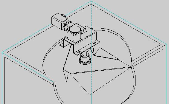
10 How does it work? A mechanical mode stirrer modifies field configuration in a cavity Signal Gen.

11 How does it work? Signal Gen. Field configuration

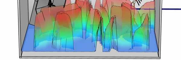
12 Statistical uniformity Maximum field level (X, Y, Z, Total) on one rotation (fixed frequency) V/m Maximum field level (X, Y, Z, Total) on 9 probe locations 1 turn of stirrer V/m The field is statistically homogeneous and isotropic within the working volume averaged over one complete rotation, from LUF 9 probe locations
13 How does it work? Calibration of the Reverb Chb provides 2 main characteristics Satistical uniformity Deviation on the maximum field of each field component (E X, E Y, E Z ) and total field (E T ), on each of the 9 probe locations must be below the allowed standard deviation limit of DO 160 Determines Lowest frequency of Use Of the MSRC Normalized E Field Field which is obtained for 1 W power delivered on the input connector of the Tx antenna Determines the power level to be provided to reach the target E-fields
14 How does it work? Design key point of the Reverberation Chamber Smaller Reverb Chb LUF will be higher Normalized E-Field will be higher Larger Reverb. Chb LUF lower (100 MHz) Normalized E-field will be lower Trade-off to determine the suitable solution to perform RS tests
15 Microwave & RF Comparison of test methods 15/ 57 NBR A


16 Anechoic Ch. Vs MSRC Free Space environment Test distance = 1 m Propagated waves, absorbed by the walls Deterministic description of the fields Anisotropic tests Reverberating environment No specific test distance Reflections on the walls Random description of the fields Isotropic tests
17 Anechoic Ch. Vs MSRC DO 160 G section 20 : both can be used for Radiated and Conducted Susceptibility DO 160 G section 21 : both can be used for Radiated and Conducted Emissions What are the criterion of choice?
18 Anechoic Ch. Vs MSRC Anechoic chamber (AC) Conducted tests possible on a test bench (shielded room) Radiated tests possible with RF absorbers on the walls Compliance of the chamber : Reflectivity level of the absorbers -6 db (100 MHz<f < 250 MHz) Reflectivity level of the absorbers -10 db (f > 250 MHz) 660 mm high absorbers typically Radiated tests done on a plane The EUT must be rotated Field strength related to test distance (1m) One single AC can be used for all CS & RS tests
19 Anechoic Ch. Vs MSRC Reverb chamber (MSRC) Conducted tests possible on a test bench (shielded room) Radiated tests without absorbers on the walls Compliance of the chamber : Lowest Frequency of Use (LUF) Normalized Field high enough to provide target field Radiated tests done on a volume The EUT needs not being rotated Field strength related to Normalized Field (dependent on MSRC size) Multiple MSRC can be used for all CS & RS tests (optimization)
20 Anechoic Ch. Vs MSRC Power levels needed to reach target field Technical difficulties & Budget increase
21 Microwave & RF Solutions for complete CS/RS tests 21/ 57 NBR A

22 Technical solutions MHz CW tests only Levels 200 V/m 3 main frequency ranges GHz CW & PM Tests Up to 1,400 V/m LPDA Antenna 1 18 GHz CW & PM Tests Up to 7,200 V/m Horn Antenna
23 Technical solutions 3 main frequency ranges 100 to 400 MHz CW field levels allow to use an Anechoic Chamber or a Reverb Chamber with available instrumentation 400 to 1,000 MHz CW field levels allow to use an Anechoic Chamber or a Reverb Chamber with available instrumentation Cat L PM field levels make the use of an Anechoic Chamber costly 1 to 18 GHz CW field levels allow to use an Anechoic Chamber or a Reverb Chamber with available instrumentation Cat L PM field levels make the use of an Anechoic Chamber unrealistic
24 Technical solutions It is possible to use several combinations for RS testing : 1 Anechoic Chb (100 MHz to 400 MHz) + 1 Reverb. Chb (400 MHz 18 GHz) Realistic for an existing laboratory with AC Possible with affordable instrumentation if cat. G & L not required 1 Anechoic Chb (100 MHz to 400 MHz) + 2 Reverb Chb ([400 MHz ; 1 GHz] & [1 ; 18 GHz]) Realistic for a laboratory with existing AC Allows to consider cat. L testing at optimized budget
25 Technical solutions It is possible to use several combinations for RS testing : 1 Reverb.Chamber (100 MHz 18 GHz) Possible but difficult for PM tests > 1 GHz (cat. F/G/L) 3 Reverb. Chambre ([100 ; 400 MHz] & [400 MHz ; 1 GHz] & [1 ; 18 GHz]) Optimized solution for a new laboratory Optimal power amplifier budget
26 Microwave & RF Siepel EOLE series 26/ 57 NBR A


27 Unique - high conductivity panels Comparison between 2 identical MSRC 20% more field with aluminum Input power reduced by 2 db
 Dimensions 7.5 x 5 x 4 m Test volume 3 x 2.3 x 1.")
28 EOLE 100 Frequency range of operation : 100 MHz to 18 (40) GHz Specifications (typ.) Dimensions 7.5 x 5 x 4 m Test volume 3 x 2.3 x 1.7 m Minimum field 400 MHz & 1W : 30 V/m
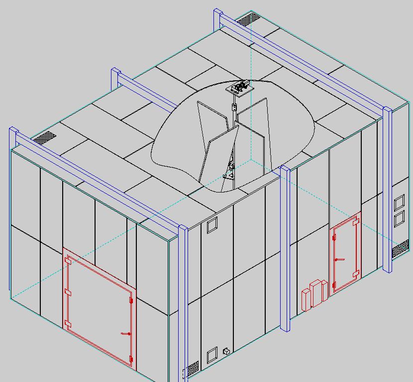
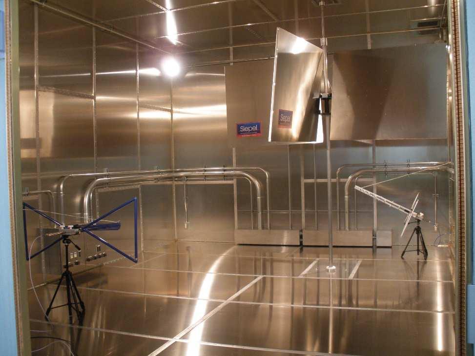
29 EOLE 100
30 EOLE 400 Frequency range of operation : 400 MHz to 18 (40) GHz Specifications (typ.) Dimensions 3.45 x 2.52 x 2.94 m Test volume 2.66 x 1.25 x 1.36 m Minimum field 1 GHz & 1W : 85 V/m
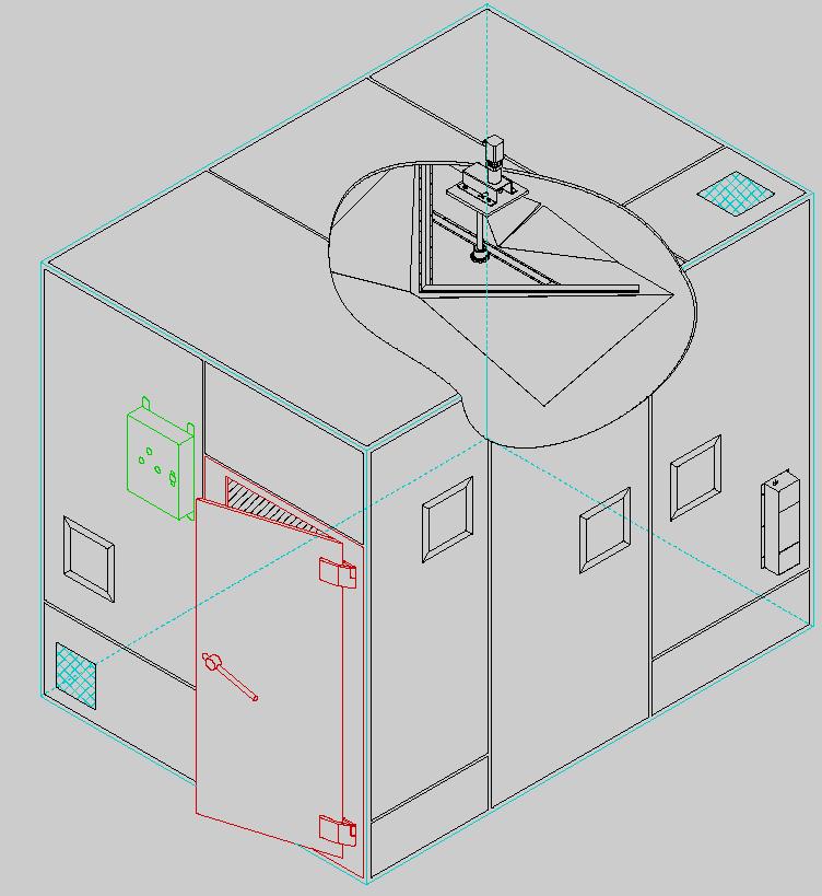
31 EOLE 400
32 EOLE 1000 Frequency range of operation : 1 GHz to 18 (40) GHz Specifications (typ.) Dimensions 1.02 x 0.86 x 1.28 m Test volume 0.72 x 0.56 x 0.4 m Minimum field 1 GHz & 1W : 170 V/m
33 EOLE 1000
34 Microwave & RF Conclusion 34/ 57 NBR A
35 DO160 - Advantages of MSRC HIGH FIELDS WITH LOW INPUT POWER TRADE OFF DIMENSIONS / LUF / POWER TOTAL GUIDANCE IN PROJECT DEFINITION
36 DO160 - Advantages of MSRC TURNKEY CAPABILITIES SINGLE RESPONSIBILITY FLEXIBLE AND UPGRADEABLE
37 Questions? Contact for information : jf.rosnarho@siepel.com or contact@siepel.com
Reverberation Chambers
 Reverberation Chambers Andy Lambourne 29 th November 2007 Contents 01 Introduction 02 Uses of a Reverberation Chamber 03 Example Facilities 04 Chamber Properties 05 Standards and Test Methods 06 Calibration
REVERBERATION CHAMBER FOR EMI TESTING
 1 REVERBERATION CHAMBER FOR EMI TESTING INTRODUCTION EMI Testing 1. Whether a product is intended for military, industrial, commercial or residential use, while it must perform its intended function in
Immunity Test System RIS 3000 / RIS 6000 acc. to IEC/EN
 Description The setup of a radiated immunity test system can be done in the conventional way with many separate instruments or in a more comfortable and less risky way with our new EMC control unit, type
AMPLIFIER RESEARCH... APPLICATION NOTE: 23
 AMPLIFIER RESEARCH... APPLICATION NOTE: 23 PRODUCTS THAT PROVIDE 200 V/m CW OR PM AT A DISTANCE OF 1 METER 1 The Amplifier / Antenna / Cell combinations shown in Table 1 provide various means of generating
Model AS18071, M1, M2 AR System 10kHz 18GHz
 Model AS18071, M1, M2 AR System 10kHz 18GHz The AS18071 AR System is a comprehensive equipment package designed to perform turnkey Radiated Susceptibility testing using the Reverberation Chamber method.
AMPLIFIER RESEARCH... APPLICATION NOTE: 20
 AMPLIFIER RESEARCH... APPLICATION NOTE: 20 AMPLIFIER RESEARCH PRODUCTS THAT PROVIDE 20 V/m CW OR PM AT A DISTANCE OF 1 METER 1 The Amplifier / Antenna / Cell combinations shown in Table 1 provide various
Laird Attn: Bill Steinike W66 N220 Commerce Ct. Cedarburg, WI Report Constructed by: Zach Wilson, EMC Technician Signature: Date: June 21, 2017
 A Test Report # 317241 Equipment Under Test: RM024 Test Date(s): June 9 and June 21, 2017 Prepared for: Laird Attn: Bill Steinike W66 N220 Commerce Ct. Cedarburg, WI 53012 Report Issued by: Adam Alger,
AMPLIFIER RESEARCH... APPLICATION NOTE: 19
 AMPLIFIER RESEARCH... APPLICATION NOTE: 19 AMPLIFIER RESEARCH PRODUCTS THAT PROVIDE 10 V/m CW OR PM AT A DISTANCE OF 1 METER 1 The Amplifier / Antenna / Cell combinations shown in Table 1 provide various
Reverberation Chambers Design and Construction Considerations for Aerospace and Military Test Requirements
 Reverberation Chambers Design and Construction Considerations for Aerospace and Military Test Requirements REVERBERATION CHAMBERS: DESIGN AND CONSTRUCTION CONSIDERATIONS FOR AEROSPACE AND MILITARY TEST
Semi Anechoic Chamber (SAC)
") 1 of 9 Semi Anechoic Chamber (SAC) Approximate Dimensions of 3m Semi Anechoic Chamber (SAC) Length: 10m Width: 9m Height: 9m Frequency range of Semi Anechoic Chamber: 9 KHz to 40 GHz Emission test (EMI):
1 of 9 Semi Anechoic Chamber (SAC) Approximate Dimensions of 3m Semi Anechoic Chamber (SAC) Length: 10m Width: 9m Height: 9m Frequency range of Semi Anechoic Chamber: 9 KHz to 40 GHz Emission test (EMI):
Electromagnetic Compatibility ( EMC )
") Electromagnetic Compatibility ( EMC ) Introduction EMC Testing 1-2 -1 Agenda System Radiated Interference Test System Conducted Interference Test 1-2 -2 System Radiated Interference Test Open-Area Test
Electromagnetic Compatibility ( EMC ) Introduction EMC Testing 1-2 -1 Agenda System Radiated Interference Test System Conducted Interference Test 1-2 -2 System Radiated Interference Test Open-Area Test
Calibration and Validation for Automotive EMC
 Calibration and Validation for Automotive EMC Wolfgang Müllner Patrick Preiner Alexander Kriz Seibersdorf Labor GmbH 2444 Seibersdorf, Austria http://rf.seibersdorf-laboratories.at rf@seibersdorf-laboratories.at
LTE Band 7. Channel
 Bandwidth 5MHz Frequency (MHz) LTE Band 7 Bandwidth 10MHz Peak To Average Ratio (db) Frequency Peak To Average Ratio (db) QPSK 16QAM (MHz) QPSK 16QAM 20775 2502.5 3.57 4.34 20800 2505 3.51 4.28 21100 2535
Schedule of Accreditation issued by United Kingdom Accreditation Service 2 Pine Trees, Chertsey Lane, Staines-upon-Thames, TW18 3HR, UK
 2 Pine Trees, Chertsey Lane, Staines-upon-Thames, TW18 3HR, UK Caddsdown Industrial Estate Clovelly Road Bideford Devon EX39 3DX Contact: Becky Scott Tel: +44 (0)1237 423388 Fax: +44 (0)1237 423434 E-Mail:
STSM: On-Site Emission Measurements
 On-Site Emission Measurements Based on Reverberation Chamber Techniques Robert Vogt, STSM - SP, Boras, Sweden 20.09 03.10.2015 CONTENTS On-site emission measurements (Motivation) Test site classification
An Introduction to EMC Testing (what can be done with scopes) Vincent Lascoste EMC Product Manager - RSF
 Vincent Lascoste EMC Product Manager - RSF") An Introduction to EMC Testing (what can be done with scopes) Vincent Lascoste EMC Product Manager - RSF Definition of ElectroMagnetic Compatibility (EMC) EMC is defined as: "The ability of devices and
An Introduction to EMC Testing (what can be done with scopes) Vincent Lascoste EMC Product Manager - RSF Definition of ElectroMagnetic Compatibility (EMC) EMC is defined as: "The ability of devices and
TEST REPORT... 1 CONTENT...
 CONTENT TEST REPORT... 1 CONTENT... 2 1 TEST RESULTS SUMMARY... 3 2 EMC RESULTS CONCLUSION... 4 3 LABORATORY MEASUREMENTS... 6 4 EMI TEST... 7 4.1 CONTINUOUS CONDUCTED DISTURBANCE VOLTAGE TEST... 7 4.2
CONDUCTED RF EQUIPMENT POWER AMPLIFIERS. Practical RF Immunity System Design Considerations
 CONDUCTED RF EQUIPMENT POWER AMPLIFIERS Practical RF Immunity System Design Considerations 1 Designing a System Key considerations are the amplifier and antenna combination Determining what Power Amplifier
Reducing Uncertainty in EMC Measurements
 Reducing Uncertainty in EMC Measurements Uncertainty In general, a standardized EMC test must be developed such that reproducible results are obtained if different parties perform the same test with the
Valon Synthesizer RFI Test Report
 Page: Page 1 of 10 VEGAS-003-A-REP Version: A Prepared By: Name(s) and Signature(s) Organization Date C.Beaudet NRAO-GB 2011-11-29 J.Ray NRAO-GB 2013-03-18 Page: Page 2 of 10 Change Record Version Date
CS114 + CS115 + CS116
 System description Test Setup for MIL-STD-461 D, E&F CS114 + CS115 + CS116 1. MONTENA EMC... 2 1.1 PRODUCTS... 3 1.2 TURN KEY MIL STD 461 TEST INSTALLATIONS... 3 2. TEST SETUP DESCRIPTION... 4 2.1 TEST
EN :2007+A1:2011 Electromagnetic compatibility Emission standard for residential, commercial and light-industrial environments
 EMC Page 3 / 33 Test report No.: EN 61000-6-3:2007+A1:2011 Electromagnetic compatibility Emission standard for residential, commercial and light-industrial environments Date of measurement: 2013-10-16
Overview of EMC Regulations and Testing. Prof. Tzong-Lin Wu Department of Electrical Engineering National Taiwan University
 Overview of EMC Regulations and Testing Prof. Tzong-Lin Wu Department of Electrical Engineering National Taiwan University What is EMC Electro-Magnetic Compatibility ( 電磁相容 ) EMC EMI (Interference) Conducted
Spider Tracks Limited
 Spider Tracks Limited REVISED TEST REPORT FOR Spider 8 Tested To The Following Standard(s)/Specification(s): RTCA/DO-160G (2010) Section: 17 Date of issue: September 19, 2017 CKC Laboratories, Inc. We
We ve Bent The Rules. AR s Bent-Element Approach Provides A Size Reduction Of Up To 75%, Along With Great Performance.
 Antennas 76 We ve Bent The Rules. AR s Bent-Element Approach Provides A Size Reduction Of Up To 75%, Along With Great Performance. AR is doing incredible things with antennas. For starters, we ve advanced
CHAPTER 6 EMI EMC MEASUREMENTS AND STANDARDS FOR TRACKED VEHICLES (MIL APPLICATION)
") 147 CHAPTER 6 EMI EMC MEASUREMENTS AND STANDARDS FOR TRACKED VEHICLES (MIL APPLICATION) 6.1 INTRODUCTION The electrical and electronic devices, circuits and systems are capable of emitting the electromagnetic
147 CHAPTER 6 EMI EMC MEASUREMENTS AND STANDARDS FOR TRACKED VEHICLES (MIL APPLICATION) 6.1 INTRODUCTION The electrical and electronic devices, circuits and systems are capable of emitting the electromagnetic
Specification for Radiated susceptibility Test
 1 of 11 General Information on Radiated susceptibility test Supported frequency Range : 20MHz to 6GHz Supported Field strength : 30V/m at 3 meter distance 100V/m at 1 meter distance 2 of 11 Signal generator
Ave output power ANT 1(dBm) Ave output power ANT 2 (dbm)
 Ave output power ANT 2 (dbm)") Page 41 of 103 9.6. Test Result The test was performed with 802.11b Channel Frequency (MHz) power ANT 1(dBm) power ANT 2 (dbm) power ANT 1(mW) power ANT 2 (mw) Limits dbm / W Low 2412 7.20 7.37 5.248 5.458
Page 41 of 103 9.6. Test Result The test was performed with 802.11b Channel Frequency (MHz) power ANT 1(dBm) power ANT 2 (dbm) power ANT 1(mW) power ANT 2 (mw) Limits dbm / W Low 2412 7.20 7.37 5.248 5.458
Application Note #38B Automotive 600V/m Radar Pulse Test Solution
 Application Note #38B Automotive 600V/m Radar Pulse Test Solution By Applications Engineering There are many hazardous electrical events in the environment that can have adverse effects on the systems
Large E Field Generators in Semi-anechoic Chambers for Full Vehicle Immunity Testing
 Large E Field Generators in Semi-anechoic Chambers for Full Vehicle Immunity Testing Vince Rodriguez ETS-Lindgren, Inc. Abstract Several standards recommend the use of transmission line systems (TLS) as
GTEM cells. Emissions and immunity testing in a single, shielded environment
 GTEM cells Emissions and immunity testing in a single, shielded environment GTEM cells Emissions and immunity testing in a single, shielded environment Function A GTEM (Gigahertz Transverse Electro Magnetic)
How will the third edition of IEC affect your test facility?
 How will the third edition of IEC 61000-4-3 affect your test facility? Changes in the standard could mean that your amplifier is no longer powerful enough Introduction The third edition of IEC 61000-4-3
Utilizing Reverberation Chambers as a Versatile Test Environment for Assessing the Performance of Components and Systems
 Utilizing Reverberation Chambers as a Versatile Test Environment for Assessing the Performance of Components and Systems Dennis Lewis The Boeing Company Technical Fellow RF / Microwave and Antenna Metrology
The NASA High Intensity Radiated Fields Laboratory. Reuben A. Williams. NASA Langley Research Center M/S 130 Hampton, Virginia
 The NASA High Intensity Radiated Fields Laboratory Reuben A. Williams NASA Langley Research Center M/S 130 Hampton, Virginia 23681-0001 ABSTRACT High Intensity Radiated Fields (HIRF) are the result of
Shielding Effectiveness Summary Results for RadiaShield Technologies, Inc. RadiaShield Fabric
 Test Date(s): July 9 through July 19, 2010 UST Project Number: 10-0164 Summary Results for Product Description The Sample Under Test (SUT) is the. The SUT is a textile which is used as a protective shield
FISCHER CUSTOM COMMUNICATIONS, INC.
 FISCHER CUSTOM COMMUNICATIONS, INC. Current Probe Catalog FISCHER CUSTOM COMMUNICATIONS, INC. Fischer Custom Communications, Inc., is a manufacturer of custom electric and magnetic field sensors for military
EMC Evaluation at Green Bank: Emissions and Shield Effectiveness
 EMC Evaluation at Green Bank: Emissions and Shield Effectiveness National Radio Astronomy Observatory Carla Beaudet Green Bank RFI Group Leader Emissions Evaluation: Standards ITU-R RA.769 specifies (typical)
Test and Measurement for EMC
 Test and Measurement for EMC Bogdan Adamczyk, Ph.D., in.c.e. Professor of Engineering Director of the Electromagnetic Compatibility Center Grand Valley State University, Michigan, USA Ottawa, Canada July
Rationale for RC Testing. Vignesh Rajamani, PhD. Research Engineer Oklahoma State University
 Rationale for RC Testing Vignesh Rajamani, PhD. Research Engineer Oklahoma State University Overview What is a reverberation chamber? Immunity testing Emissions testing Shielding effectiveness measurements
Advanced Test Equipment Rentals ATEC (2832)
") Established 1981 Advanced Test Equipment Rentals www.atecorp.com 800-404-ATEC (2832) Automotive 600V/m Pulse Radar Test with a Dual-Mode Amplifier Application note 118 (Component) Purpose - The information
Established 1981 Advanced Test Equipment Rentals www.atecorp.com 800-404-ATEC (2832) Automotive 600V/m Pulse Radar Test with a Dual-Mode Amplifier Application note 118 (Component) Purpose - The information
FCC 15B Test Report. : BTv4.0 Dual Mode USB Dongle. Address : Thompson Ave. / Lenexa, Kansas / / USA
 FCC 15B Test Report Equipment Model No. Brand Name Applicant : BTv4.0 Dual Mode USB Dongle : BT820 : Laird Technologies : Laird Technologies Address : 11160 Thompson Ave. / Lenexa, Kansas / 66219 / USA
A Test Lab Techno Corp. Report Number:1410FR27
 Mode 5: IEEE 802.11n 2.4GHz 40MHz Link Mode 2422 2437 2452 Page 41 of 85 9 Out of Band Conducted Emissions Measurement 9.1. Limit In any 100 khz bandwidth outside the frequency band in which the spread
Test specification: Section (e)(1), Radiated emissions below 40 GHz Test procedure: ANSI C63.4, Sections 8.3.2, 13.2, 13.4 Test mode: Compliance
(1), Radiated emissions below 40 GHz Test procedure: ANSI C63.4, Sections 8.3.2, 13.2, 13.4 Test mode: Compliance") Test specification: Section 15.253(e)(1), Radiated emissions below 40 GHz Test procedure: ANSI C63.4, Sections 8.3.2, 13.2, 13.4 Plot 7.2.7 Radiated emission measurements at frequency 7280 MHz Low channel
Test specification: Section 15.253(e)(1), Radiated emissions below 40 GHz Test procedure: ANSI C63.4, Sections 8.3.2, 13.2, 13.4 Plot 7.2.7 Radiated emission measurements at frequency 7280 MHz Low channel
EMC/EMI MEASURING INSTRUMENTS & ACCESSORIES SHORT-FORM CATALOG 2011
 EMC/EMI MEASURING INSTRUMENTS & ACCESSORIES SHORT-FORM CATALOG 2011 All-in-one Digital EMI Analyzer 10 Hz - 3 GHz PMM 9010/30P EMI Analyzer 10 Hz - 3 GHz Our trek started in a small laboratory over 25
FCC Test Report. : Wireless Way Richmond, BC, V6V 3A4 Canada : 47 CFR FCC Part 27 Subpart L
 FCC Test Report FCC ID Equipment Model No. Brand Name Applicant Address Standard : N7NHL7688 : Wireless Module : HL7688 : AirPrime : Sierra Wireless Inc. Received Date : Jul. 12, 2016 : 13811 Wireless
EMC ANECHOIC CHAMBERS 5-METER CHAMBERS
 ETS-Lindgren's FACT 5 Chambers offer semi-anechoic radiated emissions (RE) and fully anechoic radiated immunity (RI) compliance test capability for most international EMC compliance regulations. FACT 5
ISO INTERNATIONAL STANDARD
 INTERNATIONAL STANDARD ISO 11452-11 First edition 2010-09-01 Road vehicles Component test methods for electrical disturbances from narrowband radiated electromagnetic energy Part 11: Reverberation chamber
EMC/EMI MEASURING INSTRUMENTS & ACCESSORIES SHORT-FORM CATALOG 2009
 EMC/EMI MEASURING INSTRUMENTS & ACCESSORIES SHORT-FORM CATALOG 2009 Our trek started in a small laboratory over 25 years ago. Since then, we ve been focused on making EMC measurements easier and the measuring
E M C T E S T Y O U R SOURCE FOR TOP Q U A L I T Y TEST EQUIPMENT & E M C. w w w. h v t e c h n o l o g i e s. c o m
 E M C T E S T S O L U T I O N S P A R T N E R S F O R H V & E M C S O L U T I O N S Y O U R SOURCE FOR TOP Q U A L I T Y TEST EQUIPMENT w w w. h v t e c h n o l o g i e s. c o m Transient Immunity Generators
Qualtest, Inc. Report: REPORT REVISION RECORD
 REPORT REVISION RECORD REVISION DESCRIPTION OF CHANGE INITIAL RELEASE Page 2 of 65 QR216-02 Rev. - TABLE OF CONTENTS TITLE PAGE FOREWORD...5 SECTION 1...6 RS03 RADIATED SUSCEPTIBILITY TEST SUMMARY...6
Future In Radiated Immunity Testing
 Future In Radiated Immunity Testing Flynn Lawrence Flynn Lawrence is an Applications Engineer for AR RF/Microwave Instrumentation. At AR, Flynn is actively engaged in new application and product development
EMI Pre-Compliance Testing Solution
 99 Washington Street Melrose, MA 02176 Phone 781-665-1400 Toll Free 1-800-517-8431 Visit us at www.testequipmentdepot.com EMI Pre-Compliance Testing Solution GW Instek introduces the latest and comprehensive
FCC C2PC Test Report
 FCC C2PC Test Report FCC ID Equipment Model No. Brand Name Applicant : SQGBT800 : BTv4.0 Dual Mode USB Dongle : BT820 : Laird Technologies : Laird Technologies Address : 11160 Thompson Ave. / Lenexa, Kansas
BUREAU VERITAS. itaste svd
 BUREAU VERITAS TEST REPORT No.: (5213)095-0238 TEST REPORT To: INNOKIN TECHNOLOGY CO., LTD I Fax: I -- Attn: -- I -- I Address: Buildinq 6, XinXinTian Industrial Park, XinSha Road, Sha.Jinq street, ShenZhen,
System description 4. SERVICES ONSITE INSTALLATION AND TRAINING SYSTEM ACCEPTANCE MAINTENANCE... 7
 Ultra Wide Band test setup System description 1. UWB TEST SYSTEM DESCRIPTION... 2 2. SYSTEM MONITORING... 5 3. OTHER MEASUREMENT SYSTEMS & ACCESSORIES... 6 3.1 OSCILLOSCOPE & SHIELDED ENCLOSURE... 6 3.2
TEST REPORT: ELECTROMAGNETIC COMPATIBILITY - ESA Regulation Consolidated to Supplement 2 (Revision 4 Amendment 2)
") Vehicle Certification Agency, 1 The Eastgate Office Centre Eastgate Road, Bristol, BS5 6XX, United Kingdom. Telephone: +44 (0) 117 951 5151 Fax: +44 (0) 117 952 4103 Email: enquiries@vca.gov.uk www.dft.gov.uk/vca
Vehicle Certification Agency, 1 The Eastgate Office Centre Eastgate Road, Bristol, BS5 6XX, United Kingdom. Telephone: +44 (0) 117 951 5151 Fax: +44 (0) 117 952 4103 Email: enquiries@vca.gov.uk www.dft.gov.uk/vca
Test sites for EMC measurements
 Test sites for EMC measurements EMV Fachtagung 21. Januar 2014 Christophe Perrenoud www.montenaemc.ch montena emc Route de Montena 75 CH - 1728 Rossens Tel. +41 26 411 93 33 Fax +41 26 411 93 30 office.emc@montenaemc.ch
E-Field Uniformity Test Volume In Gtem Cell Based On Labview
 www.ijecs.in International Journal Of Engineering And Computer Science ISSN:2319-7242 Volume 4 Issue 4 April 215, Page No. 11646-1165 E-Field Uniformity Test Volume In Gtem Cell Based On Labview Dominic
Schedule of Accreditation issued by United Kingdom Accreditation Service 2 Pine Trees, Chertsey Lane, Staines-upon-Thames, TW18 3HR, UK
 2 Pine Trees, Chertsey Lane, Staines-upon-Thames, TW18 3HR, UK EMC Test House EME Department FPC 65 PO Box 5 Filton Bristol BS34 7QW Contact: Mr Peter Duncan Tel: +44 (0)117 931 8248 E-Mail: peter.duncan@mbda.co.uk
Model AS08010, M1 AR System 10kHz 8GHz
 Model AS08010, M1 AR System 10kHz 8GHz The AS08010 and AS08010M1 Systems consist of the AR equipment, listed below. Please refer to individual product specification sheets for details. The export classification
Report Of. Shielding Effectiveness Test For. DefenderShield. Test Date(s): September 1 October 2, 2012
: September 1 October 2, 2012") Report Of Test For Test Date(s): September 1 October 2, 2012 UST Project No: Total Number of Pages Contained Within This Report: 15 3505 Francis Circle Alpharetta, GA 30004 PH: 770-740-0717 Fax: 770-740-1508
Report Of Test For Test Date(s): September 1 October 2, 2012 UST Project No: Total Number of Pages Contained Within This Report: 15 3505 Francis Circle Alpharetta, GA 30004 PH: 770-740-0717 Fax: 770-740-1508
Shielding Effectiveness Report HQCD
 HQCD Mates with QSH, QTH, QSH-EM Description: 0.50mm Q Strip High Speed Coax Cable Assembly Samtec, Inc. 2005 All Rights Reserved Table of Contents Product Overview... 1 Test Overview... 1 Shielded Room
Physically and Electrically Large Antennas for Antenna Pattern Measurements and Radar Cross Section Measurements in the Upper VHF and UHF bands
 Physically and Electrically Large Antennas for Antenna Pattern Measurements and Radar Cross Section Measurements in the Upper VHF and UHF bands Vince Rodriguez, PhD Product Manager, Antennas ETS-Lindgren,
MIL STD 461F TEST REPORT. For. Rugged PDA. Model Number: P37B. Trade Name: N/A. Issued to
 MIL STD 461F TEST REPORT For Rugged PDA Model Number: P37B Trade Name: N/A Issued to ACA Digital Corporation 17F.,No 866-7, Zhongzheng Rd, Zhonghe City, Taipei County, 235, Taiwan, R,O,C Issued by Compliance
ITUNER NETWORKS CORPORATION EMC REPORT Fremont Blvd. Fremont, CA
 Shenzhen BST Technology Co., Ltd. ITUNER NETWORKS CORPORATION EMC REPORT Prepared For : ITUNER NETWORKS CORPORATION 47801 Fremont Blvd. Fremont, CA. 94538 Product Name: PicoPSU-150 Trade Name: PicoPSU
SAC-10 Plus Triton Class
 Anechoic Chamber SAC-10 Plus Triton Class SAC-10 Plus Triton Class Frankonia s anechoic chamber for 10.0 & 3.0 m measuring distance with triple test axes FRANKONIA CONCEPT SAC-10 Plus Triton Class Frankonia
DARE!! Instruments Application Note GHz Radiated RF Immunity Testing
 DARE!! Instruments Application Note 14.001 1 6 GHz Radiated RF Immunity Testing EM Field Generation Contents 1. Introduction... 4 2. Power or Field?... 4 3. The conventional setup... 5 4. Antenna and Amplifier
EMC LAB EQUIPMENT CALIBRATION SCHEDULER
 Page 1 of 7 Purpose: To maintain a list of equipment scheduled for calibration and the test methods where is involved. Responsibility: Technical manager, EMC lab technicians Overview: The actual calibration
R&S IMS Hardware Setup according IEC / EN (radiated immunity) Products: R&S IMS, R&S NRP-Z91, HL046E. Application Note
 Products: R&S IMS, R&S NRP-Z91, HL046E. Application Note") Products: R&S, R&S NRP-Z91, HL046E R&S Hardware Setup according IEC / EN 61000-4-3 (radiated iunity) Application Note This application note describes the general setup and required equipent for EMC easureents
Products: R&S, R&S NRP-Z91, HL046E R&S Hardware Setup according IEC / EN 61000-4-3 (radiated iunity) Application Note This application note describes the general setup and required equipent for EMC easureents
Downloaded from 1. THE FOLLOWING PAGES OF MIL-STD-462D HAVE BEEN REVISED AND SUPERSEDE THE PAGES LISTED:
 NOTICE OF CHANGE METRIC 10 April 1995 MILITARY STANDARD MEASUREMENT OF ELECTROMAGNETIC INTERFERENCE CHARACTERISTICS TO ALL HOLDERS OF : 1. THE FOLLOWING PAGES OF HAVE BEEN REVISED AND SUPERSEDE THE PAGES
TEST REPORT. Covering the DYNAMIC FREQUENCY SELECTION (DFS) REQUIREMENTS OF. FCC Part 15 Subpart E (UNII) Xirrus Model(s): XN4
 REQUIREMENTS OF. FCC Part 15 Subpart E (UNII) Xirrus Model(s): XN4") TEST REPORT Covering the DYNAMIC FREQUENCY SELECTION (DFS) REQUIREMENTS OF FCC Part 15 Subpart E (UNII) Xirrus Model(s): XN4 COMPANY: TEST SITE: Xirrus 370 North Westlake Blvd., Suite 200 Westlake Village,
TEST REPORT Covering the DYNAMIC FREQUENCY SELECTION (DFS) REQUIREMENTS OF FCC Part 15 Subpart E (UNII) Xirrus Model(s): XN4 COMPANY: TEST SITE: Xirrus 370 North Westlake Blvd., Suite 200 Westlake Village,
EXHIBIT 7: MEASUREMENT PROCEDURES Pursuant 47 CFR 2.947
 EXHIBIT 7: MEASUREMENT PROCEDURES Pursuant 47 CFR 2.947 7.1 RF Power -- Pursuant to 47 CFR 2.947(c) Method of Conducted Output Power Measurement: Adaptation of TIA/EIA-603-A clause 2.2.1 for Pulsed Measurements
MEASUREMENT REPORT FCC Part 15B
 MRT Technology (Suzhou) Co., Ltd Phone: +86-512-66308358 Report V0sion: V03 Fax: +86-512-66308368 Issue Date: 02-05-2016 Web: www.mrt-cert.com MEASUREMENT REPORT FCC Part 15B FCC ID: APPLICANT: YZZGXP2160
Alternative Radiated Emission Test Methods Progress Achieved in IND60 Project
 Alternative Radiated Emission Test Methods Progress Achieved in IND60 Project Project EMRP IND60: Improved EMC test methods in industrial environments Mohammed Salhi 05-09 September 2016 Wroclaw, Poland
TEST SUMMARY. Prüfbericht - Nr.: Test Report No FIELD STRENGTH OF FUNDAMENTAL RESULT: Passed % BANDWIDTH RESULT: Passed
 Seite 2 von 24 Page 2 of 24 TEST SUMMARY 5.1.1 FIELD STRENGTH OF FUNDAMENTAL RESULT: Passed 5.1.2 99% BANDWIDTH RESULT: Passed 5.1.3 SPURIOUS EMISSION RESULT: Passed 5.2.1 SPURIOUS EMISSION RESULT: Passed
STC Test Report. The Hong Kong Standards and Testing Centre Ltd.
 Date: 2011-11-15 Page 2 of 15 CONTENT: Cover Page 1 of 15 Content Page 2 of 15 1.0 General Details 1.1 Equipment Under Test [EUT] Page 3 of 15 Description of sample(s) 1.2 Description of EUT operation
EMC TEST REPORT for : DONGGUAN EVER DEVELOPMENT ELECTRONIC CO., Electronic calculator Model No.: KF15758
 Page 1 of 20 Report No. R011604553E EMC TEST REPORT for DONGGUAN EVER DEVELOPMENT ELECTRONIC CO., LTD. Electronic calculator Model No.: KF15758 Prepared for Address Prepared by Address : DONGGUAN EVER
Trees, vegetation, buildings etc.
 EMC Measurements Test Site Locations Open Area (Field) Test Site Obstruction Free Trees, vegetation, buildings etc. Chamber or Screened Room Smaller Equipments Attenuate external fields (about 100dB) External
TEST REPORT FROM RADIO FREQUENCY INVESTIGATION LTD.
 TEST REPORT FROM RADIO FREQUENCY INVESTIGATION LTD. Test Of: Wood & Douglas Ltd ST500 Transmitter Test Report Serial No: RFI/EMCB2/RP39403B This Test Report supersedes RFI Test Report No.: RFI/EMCB1/RP39403B
RF Shielded rooms. Controlled Electromagnetic Environments
 RF Shielded rooms Controlled Electromagnetic Environments RF shielded rooms 03 Inner finishing 05 Tempest qualified rooms 05 Radio astronomy applications 06 MRI rooms 07 Controlled Electromagnetic Environments
STC Test Report. Date : Page 1 of 13 No. : HM161169
 Date : 2009-05-11 Page 1 of 13 Applicant (ATS001): Atech Scientific Measurement Limited. Room A-C, 18 Floor, Luk Hop Ind. Bldg, 8 Luk Hop Street, Kowloon Manufacturer: Atech Scientific Measurement Limited.
FCC & IC Certification. Test Report. FCC & Industry Canada Certification. Test Report. for Hetronic USA FCC ID: LW9-CS434TXN IC ID: 2219A-CS434TXN
 FCC & IC Certification Test Report FCC & Industry Canada Certification Test Report for Hetronic USA March 3, 2005 Prepared for: Hetronic USA 4300 Highline Blvd Building 4 Oklahoma City, OK 73108 Prepared
Test Report. Product Name: Wireless 11g USB Adapter Model No. : MS-6826, UB54G FCC ID. : DoC
 Test Report Product Name: Wireless 11g USB Adapter Model No. : MS-6826, UB54G FCC ID. : DoC Applicant : MICRO-STAR INT L Co., LTD Address : No 69, Li-De st., Jung-He City, Taipei Hsien, Taiwan, R.O.C Date
Revision history. Revision Date of issue Test report No. Description KES-RF-14T0042 Initial
 Page (2 ) of (34) Revision history Revision Date of issue Test report No. Description - 2014.08.25 Initial Page (3 ) of (34) TABLE OF CONTENTS 1. General information... 4 1.1. EUT description... 4 1.2.
EN 55015: 2013 Clause Pass. EN 55015: 2013 Clause Pass. EN 55015: 2013 Clause Pass
 Reference No.: WTD15S0730643E Page 2 of 42 1 Test Summary Test Item Conducted Disturbance at Mains Terminal, 9kHz to 30MHz Radiation electromagnetic disturbance, 9kHz to 30MHz Radiation Emission, 30MHz
Shielding Effectiveness Report HQDP
 HQDP Mates with QSH-DP, QTH-DP Description: 0.50mm 100Ω Differential 30 AWG Twinax Cable Assembly Samtec, Inc. 2005 All Rights Reserved Table of Contents Product Overview... 1 Test Overview... 1 Shielded
Measurement of Shielding Effectiveness. Nikhil Jain
 Measurement of Shielding Effectiveness Nikhil Jain 1 Outline Introduction Scope Equipment Measurement Process Test Report Testing at DoT/TEC Other Activities Conclusion 2 About BNN Communication Engineers
FCC ID: A3LSLS-BD106Q. Report No.: HCT-RF-1801-FC003. Plot Data for Output Port 2_QPSK 9 khz ~ 150 khz Middle channel 150 khz ~ 30 MHz Low channel
 Plot Data for Output Port 2_QPSK 9 khz ~ 150 khz Middle channel 150 khz ~ 30 MHz Low channel 30 MHz ~ 1 GHz Middle channel 1 GHz ~ 2.491 GHz Low channel 2.695 GHz ~ 12.75 GHz High channel 12.75 GHz ~ 26.5
FCC & RSS-216 (Class II Permissive Change) Wireless Power Transfer Report. for A Acer Incorporated
 Wireless Power Transfer Report. for A Acer Incorporated") Page 1 of 17 FCC 15.209 & RSS-216 (Class II Permissive Change) Wireless Power Transfer Report for A Acer Incorporated 8F., No.88, Sec. 1, Xintai 5th Rd., Xizhi, New Taipei City 22181, Taiwan (R.O.C) Product
Page 1 of 17 FCC 15.209 & RSS-216 (Class II Permissive Change) Wireless Power Transfer Report for A Acer Incorporated 8F., No.88, Sec. 1, Xintai 5th Rd., Xizhi, New Taipei City 22181, Taiwan (R.O.C) Product
TABLE OF CONTENTS. 6. PHOTOGRAPH Photo of Conducted Emission Measurement Photo of Radiation Emission Measurement...
 TABLE OF CONTENTS 1. SUMMARY OF TEST RESULTS... 4 2. GENERAL INFORMATION... 5 2.1 Details of E.U.T.... 5 2.2 Description of Support Device... 5 2.3 Block Diagram of Test Setup... 5 2.4 Test Facility...
Mode-Stirred Method Implementation for HIRF Susceptibility Testing and Results Comparison with Anechoic Method
 NASA/TM-2001-211033 Mode-Stirred Method Implementation for HIRF Susceptibility Testing and Results Comparison with Anechoic Method Truong X. Nguyen and Jay J. Ely Langley Research Center, Hampton, Virginia
Measurement of RF Emissions from a Caterpillar Inc. MSS3s RF ID Key Fob
 Measurement of RF Emissions from a Caterpillar Inc. MSS3s RF ID Key Fob For Caterpillar Inc. 330 S.W. Adams Street Peoria, IL 61630 P.O. Number JBL 11260 Date Tested May 11, 2016 Test Personnel Mark Longinotti
BS EN TESTS ON THE IT TOXIC GAS DETECTOR MODULE
 Page 1 of 18 Interference Testing And Consultancy Services (Pty) Ltd ITC SERVICES (PTY) LTD Reg 88/002032/07 Plot 44 Kameeldrift East, Pretoria Private Bag X13 Lynn East 0039 Republic of South Africa Tel
EMC TEST REPORT for LEDELS LIGHTING CO., LTD. LED module Model No. : LL-F12T4815X6B
 Page 1 of 27 Report No. R011412016E-1 EMC TEST REPORT for LEDELS LIGHTING CO., LTD LED module Model No. : LL-F12T4815X6B Prepared for : LEDELS LIGHTING CO., LTD Address : 5F, Block C, Mingjinhai Ind. Park,
7. Transmitter Radiated Spurious Emissions and Conducted Spurious Emission
 7. Transmitter Radiated Spurious Emissions and Conducted Spurious Emission 7.1 Test Setup Refer to the APPENDIX I. 7.2 Limit According to 15.247(d), in any 100 khz bandwidth outside the frequency band
EN v1.2.1 ( ) TEST REPORT FOR n 1X2 PCIe MINICARD TRANSCEIVER MODEL NUMBER: AR5B91 REPORT NUMBER: 08U
 TEST REPORT FOR n 1X2 PCIe MINICARD TRANSCEIVER MODEL NUMBER: AR5B91 REPORT NUMBER: 08U") EN 301 489-17 v1.2.1 (2002-08) TEST REPORT FOR 802.11n 1X2 PCIe MINICARD TRANSCEIVER MODEL NUMBER: AR5B91 REPORT NUMBER: 08U11615-3 ISSUE DATE: FEBRUARY 29, 2008 Prepared for ATHEROS COMMUNICATIONS, INC.
EN 301 489-17 v1.2.1 (2002-08) TEST REPORT FOR 802.11n 1X2 PCIe MINICARD TRANSCEIVER MODEL NUMBER: AR5B91 REPORT NUMBER: 08U11615-3 ISSUE DATE: FEBRUARY 29, 2008 Prepared for ATHEROS COMMUNICATIONS, INC.
Test Report. FCC Part 15, Subpart C, Section Industry Canada RSS-210, Issue 7
 Test Report FCC Part 5, Subpart C, Section 5.247 Industry Canada RSS-, Issue 7 Report Number: CWD67-Cert Model: CWD67 Date: March 3, 0 Prepared by: Grace Lin Date: Mar. 3, 0 Grace Lin, Sr. Compliance Engineer
GPS Active Antenna With GPRS Measurement Report
 GPS Active Antenna With GPRS Measurement Report Summary: This report is to account for the measurement setup and results of 4x23mm and mm height GPS active antenna combined with GPRS antenna measurement.
EMC TEST REPORT. for. Coliy Technology Co.,Ltd. Fluxgate Gaussmeter
 Page 1 of 48 EMC TEST REPORT for Coliy Technology Co.,Ltd. Fluxgate Gaussmeter Prepared for : Coliy Technology Co.,Ltd. Address : Block B,9 th Floor,Xinzhongtai Business Building,Gushu 2nd Road,Xi Town,Bao
Practical Considerations for Radiated Immunities Measurement using ETS-Lindgren EMC Probes
 Practical Considerations for Radiated Immunities Measurement using ETS-Lindgren EMC Probes Detectors/Modulated Field ETS-Lindgren EMC probes (HI-6022/6122, HI-6005/6105, and HI-6053/6153) use diode detectors