RFI In Audio Systems Pin 1 Problems, Poor Shielding, and Poor Input/Output Filtering. The Heart of the Problem
|
|
|
- Louise Curtis
- 6 years ago
- Views:
Transcription
1 RFI In Audio Systems Pin 1 Problems, Poor Shielding, and Poor Input/Output Filtering Jim Brown Audio Systems Group, Inc. Chicago Santa Cruz jim@audiosystemsgroup.com The Heart of the Problem Audio equipment can work as a radio receiver if we allow it to do so The wires inside our equipment, and cables that interconnect our equipment, are antennas, and can bring radio signals into our gear Some of our equipment is poorly designed 1
2 Square Law Detection Diodes Transistors IC s Square Law Detection Diodes Transistors IC s 2
3 A Textbook λ /2 Dipole A Microphone and its Cable can form a Dipole 3
4 Basic Random Long Wire Basic Random Long Wire AUDIO EQUIPMENT 4
5 Common Mode Coupling I/O wiring acts as long wire antenna Victim Equipment Differential Mode Coupling I/O wiring is not band-pass filtered Trash Trash Input Victim Equipment Output Trash 5
6 Poor Equipment Shielding Internal wiring is receiving antenna Victim Equipment The Principle of Reciprocity Coupling Works Both Ways If the coupling is passive, what helps minimize received interference will generally also help reduce transmitted noise Relative strength of coupling depends on impedances of the coupled circuit, and may not be equal in both directions 6
7 Common Mode Coupling I/O wiring acts as transmitting antenna Noise Source Differential Mode Coupling I/O wiring is not band-pass filtered Noise Source Trash Input Output Trash 7
8 Poor Equipment Shielding Internal wiring is transmitting antenna Noise Source Radio Interference Sources AM Broadcast Transmitters FM Broadcast Transmitters Television Broadcast Transmitters Ham Transmitters Digital Wireless Mics Radiated Noise from Lighting, etc. Variable Speed Motors Cell Phones, Wireless PDA s 8
9 Variable-Speed Drive Motors Current Loop Current Loop Current Loop Variable Speed Drive Motors Operates by chopping DC to form a variable width pulse khz typical switching frequencies Harmonics extend to hundreds of khz Stray capacitance (and filter capacitors) between motor and earth causes very large currents to flow on building structure Establishes a very large current loop Controllers often widely separated from motors to make installation easier 9

10 Variable Speed Drive Motor Solutions Minimize the size of the current loops Locate transformer, controller, and motor in closest possible proximity to each other Transformer should have delta primary, wye secondary, bonded very close to motor Prevents feeders to transformer from being part of the current loop Twist neutral and phase conductors Typical Audio Noise Spectrum on Ground dbu (16 mv) Measured between two outlets in my office 10
11 RF Spectrum Analyzer 0 1 MHz 0 Hz 1 MHz Measured between two different outlets in my office, one a conventional outlet, and one an IG outlet, into a 75 ohm load Line Filters Can Add Noise to Ground 11
12 Other Noise on Ground Leakage currents to green wire Power transformer stray capacitances Intentional currents to green wire Line filter capacitors Power wiring faults Shunt mode surge suppressors Magnetic coupling from mains power Harmonic current in neutral Motors, transformers Primary Coupling Mechanisms Pin 1 problems Improper shield termination within equipment Differential noise on signal pair Inductive imbalance between shield and signal conductors -- Shield-current-induced noise (SCIN) Capacitance imbalance of cable Inadequate low-pass filtering lets it in the box Common mode noise Inadequate shielding of internal wiring 12
13 Pin 1 in Cable-Mounted Connectors Pin 1 is the shield contact of XL connectors (AES ) No connection should be made to the shell of cable-mounted connectors Pin 1 Within Equipment Pin 1 is the shield contact of XL connectors Cable shields must go to the shielding enclosure (and ONLY to the shielding enclosure) (AES48) If shields go inside the box first (to the circuit board, for example), common impedances couple shield current at random points along the circuit board! Noise is added to the signal 13
14 Pin 1 in Balanced Interfaces Pin 1 in Balanced Interfaces 14
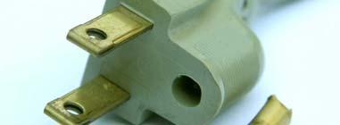
15 How Does It Happen? How Does It Happen? Pin 1 of XL s go to chassis via circuit board and ¼ connectors (it s cheaper) XLR shell not connected to anything! RCA connectors not connected to chassis 15

16 The G terminal goes to the enclosure, right? Well, sort of, but it s a long and torturous journey! Input Terminals Screw Screw 16


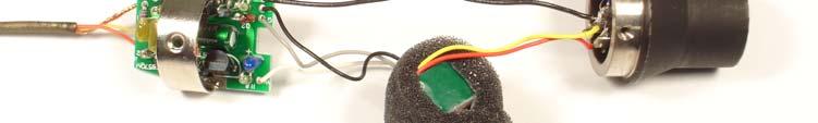
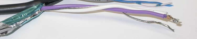
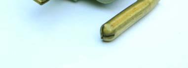
17 The Right Way A screw to connect the shields A classic RF pin 1 problem in a microphone Black wire goes to enclosure (good) Far too LONG - Inductance makes it high impedance MHz, 60 Ω at 850 MHz Orange wire goes to circuit board common Common impedance couples RF to circuit board 17


18 The Pin 1 Problem in Microphones X A pin 1 problem at RF Shield goes through connector retaining screw MHz, 30 Ω at 850 MHz Black wire is circuit board common Common impedance couples RF to circuit board This mic has RF problems 18


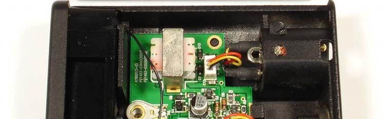
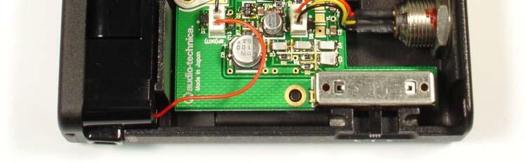
19 A better connection for pin 1 Broad, short copper, pressure fit to enclosure Less inductance Still some common impedance to circuit board 100 pf capacitors, common mode choke Much better RF performance, still not perfect 19

20 20


21 Pin 1 in Unbalanced Interfaces Where are the Chassis Connections for this laptop s sound card? Hint: It isn t an audio connector shell! That metal is a shield, but not connected to connectors And the cover is plastic too 21
22 Where are the Chassis Connections for this laptop s sound card? Yes, it s the DB9 and DB25 shells! Testing for Pin 1 Problems 22


23 John Wendt s Hummer Test for Pin 1 Problems Drive pin 1 Listen to the output If you hear it, you have a problem RF Pin 1 Test Setup for Equipment RF Source Drive pin 1 Listen to the output If you hear it, you have a problem 23


24 A Massive Pin 1 Problem in a Compressor CB Plastic body connectors not connected to chassis Massive Pin 1 problem! Pin 1 test hits threshold of compression MHz! The CE sticker assures EMC? Not here! 24


25 Pin 1 problems in a 4-channel mixer AM Radio VHF TV Pin 1 problems in its replacement VHF TV AM Radio 25

26 Pin 1 susceptibility of a much better product Sound Devices Mix Pre Two Mics From Manufacturer #4 VHF TV 26


27 Mics from three manufacturers with fairly good performance VHF TV Three mics from manufacturer #2 VHF TV 27

28 Four mics from manufacturer #1 VHF TV Why are Cell Phones Difficult? Very close to our equipment Ultra high frequency = very short wavelength Short wavelengths are difficult to filter Short wavelengths are difficult to shield Small openings let RF in 100% AM, short square pulses 28
 Spectrum of detected GSM or IDEN (Nextel)")
29 2 W peak 100 mw avg Low Duty Cycle Waveform of typical GSM and IDEN Cell Phone. Generically, it is Time Division Multiplex (TDMA) Spectrum of detected GSM or IDEN (Nextel) Cell Phone 29
30 Why are Cell Phones Difficult? Very close to our equipment Short wavelengths are difficult to filter Short wavelengths are difficult to shield 100% AM, short square 217 Hz pulses 2 W peak power, 100 mw average Detected spectrum is midrange audio Equipment designers have ignored them Cable construction is part of the problem! No cable is perfect Inductive imbalance (SCIN) Capacitive imbalance Imperfect shielding (tiny openings in braid) Even small imperfections become more important at higher frequencies No effect on audio BIG effect on RFI 30

31 Foil/Drain Shield Braid/Drain Shield Braid/Foil Shield Inductive Imbalance 31

32 The drain wire is coupled more closely to the white conductor So shield current induces more voltage on white than violet Inductive Imbalance Below about 5 MHz, most shield current in a foil/drain shield flows in the drain wire As a result of cable construction, the drain wire couples more closely to one signal conductor than the other That is, M 1-S is not equal to M 2-S 32

33 It s a 3-Winding Transformer Red Black Shield So Equipment Needs RF Filtering! Antenna action induces common mode RF to equipment Need common mode filtering Cable imbalances convert common mode to differential mode Need differential mode filtering 33
34 Current Flows in Loops Where does the return current flow? Large loop area = strong magnetic coupling Long wires = better antennas Antennas Work Without a Loop Most efficient if λ/4 or odd multiple of λ/4 Start kicking in at λ/20 Generally need something to be the other half of the antenna Current and voltage peak λ/4 apart, repeat at intervals of λ/2 34
35 Antennas Inside Equipment Wires and circuit traces are antennas too Shield the equipment Add a ground plane on a second layer Turns each circuit trace into a transmission line Return current flows on the ground plane under the trace Minimizes the loop area Minimizes antenna action Microstrip (one ground plane) Stripline (two ground planes sandwich the trace) Enemies of Good Shielding Plastic cases Paint Openings in shielded cases Slots 35


36 36
37 Is a Cable Shield Important for Balanced Audio Cables? Shielded Twisted Pair The bad: The shield provides no magnetic shielding The shield can cause SCIN, degrading noise rejection Unequal capacitances between conductors and the shield can degrade noise rejection Provides a current path to excite pin 1 problems 37
38 Shielded Twisted Pair The good: A cable shield provides E-field shielding Connection should by < λ/20 Can be important for crosstalk Connecting the shield minimizes common mode voltage at the point of connection Twisting Twisting with good symmetry causes induced voltages and currents to be more closely balanced (equal) in the two conductors Most pronounced with near field sources A tighter twist ratio reduces coupling Improves the balance in the presence of fields that vary along the cable Improves the balance at higher frequencies 38


39 Twisting and Noise Coupling Cancellation of induced voltages occurs in the receiver, not in the cable! For magnetic fields and electromagnetic fields, helps in balanced or unbalanced circuits For low frequency electric fields, helps only in balanced circuits Loudspeaker cables should be twisted pairs to reject RF Maintain Twisting Right Up to the Pins 39
40 An Experiment Cable #1 Belden 1800F AES3, braid/drain Conventional wiring, shield to pin 1 Cable #2 Belden 1752A Unshielded CAT6 One pair connects pins 2 and 3 at each end One pair tied together to pin 1 at each end Test: Cable connects dynamic mic to mic preamp, gain set to very high level. Tape demagnetizer, Nextel phone, 5w VHF/UHF talkie are moved along cable to inject interference. An Experiment Results: Neither cable coupled audible interference from demagnetizer except at connector mating to an extension cable Neither cable coupled audible interference from the radios 40
41 An Experiment Repeat w/ condenser mics with RFI problems Mic #1 RF interference with unshielded CAT6 cable was noticeably less audible than with shielded twisted pair! ~ 6-10 db Mic #2 RF interference was more audible with unshielded CAT6 3-6 db Why the difference? Common mode or differential mode susceptibility within the mic! Impedance of mic at RF! An Experiment Conclusions: While the experiment is neither rigorous or conclusive, it reinforces assertions that: Twisting is far more important than shielding A cable shield can degrade immunity 41
42 Using Ferrites to Tame the Antennas Basic Random Long Wire AUDIO EQUIPMENT 42
, so not much interference")
43 Testing mics and input gear for RFI AM Radio 50kW on 720 khz Mics Equipment Setup Gas Generator A poor RF ground (only the capacitance), so not much interference 43
44 A better RF ground (the ground stake), so much more interference No RF ground for the mic, so no interference 44


45 But when my assistant held the mic in his hand, some mics had RFI Ferrites can block the current! 45
46 Common Mode Current I/O wiring acts as long wire antenna Antenna current flows lengthwise on wiring Audio Equipment Ferrites outside the box can Help a Lot! Common Mode Current Pin 1 Problems SCIN capacitive imbalance Audio Equipment Ferrites outside the box can Help a Lot! 46
47 Differential Mode Current I/O wiring is not band-pass filtered Noise is between + and terminals of wiring Trash Input Audio Equipment Output Trash Ferrites can be used inside the box as part of low pass filters Poor Equipment Shielding Internal wiring is the receiving antenna Audio Equipment Ferrites don t help at all! 47
48 2.4 o.d. Different sizes and shapes 1 i.d. 1 i.d i.d. An AM Broadcast Choke 14 turns of mic cable around this ferrite can kill AM broadcast RFI 48
49 This choke reduced the current, and thus the RFI This Clamp-On forms a choke that can kill interference from FM and TV 49
50 What s a Ferrite? A ceramic consisting of an iron oxide manganese-zinc 1-30 MHz (AM broadcast, hams) nickel-zinc 30 MHz-1 GHz (FM, TV, cell phones) Has permeability ( µ ) much greater than air Better path for magnetic flux than air Multiplies inductance of a wire passed through it Is very lossy at radio frequencies Does not affect audio A (too) simple equivalent circuit of a wire passing through a ferrite 50

51 Impedance of Wire Through Ferrite 1 MHz 10 MHz 100 MHz 1 GHz It s Really a Parallel Resonance Resonance 51
52 Where s the Capacitance here? From one end of the choke to the other, through the permittivity of the ferrite (it is a dielectric!) A Ferrite Mix Optimized for UHF Resonance 52


53 VHF (#43) mix, different lengths! Differing Dimensions Change Shape of Resonance Longer Shorter Same mix, more turns AM Radio Z N = N 2 * Z 1 53


54 Same mix, even more turns AM Radio #31 Mix is Best for AM Broadcast RFI AM Radio 54


55 Some materials have a second resonance (Fair-Rite #78) 3 turns 5 turns Internal Resonance The Coil 55
56 A Better Equivalent Circuit Coil L C is the inductance of the coil C C is the stray capacitance of the coil R C is the resistance of the wire. L C and C C form the resonance that moves! A Better Equivalent Circuit Ferrite L D and C D represent the dimensional resonance of the ferrite itself R D is the loss within the ferrite 56
57 What Causes this Resonance? The ferrite material (called the mix ), and The physical dimensions of the ferrite core. The velocity of propagation within the ferrite establishes standing waves within the core V P = µε (that is, permeability * permittivity) Dimensional resonance occurs when the crosssection is a half-wavelength Frequency of the resonance depends on: Velocity of propagation (depends on the mix ) Dimensions of the cross-section of the flux path How About Mic Snakes? 2.4 o.d. 1 i.d. 1 i.d i.d. 57
58 If You Can t Remove the Connector 2.4 o.d. 1 i.d. 1 i.d i.d. If you can t easily remove the connector 58

59 Biggest Clamp-On, #31 Sometimes you can t take the connector off Fair-Rite Data for Biggest Clamp-On, # ,000 Frequency, MHz 59
60 Techniques for Suppression You May Not Need an Elephant Gun Most detection is square law, so: A 10 db reduction in RF level reduces audible interference by 20 db But we must add enough impedance to overcome the threshold effect 60
61 Threshold Effect Example: Our antenna is short, so looks capacitive Without the choke, the total antenna circuit is Ω, and we add a choke that is Ω, Z T = (150 j260) + (150 +j260) = 300 Ω Our choke has not helped! Threshold Effect But if we make the choke larger (more turns or more cores in series), additional R S will begin to reduce the current. Increasing R T to 425Ω (3 db) reduces detected RF by 6 db, and increasing R T to 600Ω (6 db) reduces detected RF by 12 db (assuming no change in X S ). 61

62 Threshold Effect For brute force suppression, the ferrite choke should add enough series R that the resulting Z is 2x the series Z of the antenna circuit without the choke. This reduces RF current by 6 db, and detected RF by 12 db. Very little suppression occurs until the added R is at least half of the starting Z. Capacitance Can Help a Lot Outside the box, we re stuck with what the designer provided, so a big ferrite is needed Inside the box, we can use a much smaller ferrite part if we provide the capacitor 62
63 Criteria for Good Suppression Choke should be predominantly resistive With voltage divider (capacitor across input) A few hundred ohms can be very effective No voltage divider (brute force) 500 1,000 ohms typically needed to hit threshold More is better 1,000 ohms R S is a minimum design goal More is better Saturation Ferrites saturate at high power levels, reducing µ If both conductors of high power circuits are wound through core, the fields cancel, so only the common mode current contributes to saturation This allows ferrites to be effective on loudspeaker and power wiring 63
64 They can look alike, but be very different #43 #78 #61 #31 They re brittle! 64
65 Golden Rules to Avoid RFI Loudspeaker Cables Always use TWISTED PAIR Shielding is not important Exotic cable is a waste of money This expensive loudspeaker cable makes equipment vulnerable to RFI Parallel wire (zip cord) has very poor RFI rejection 65


66 Twisted pair cables help equipment reject RFI #12 POC * is great loudspeaker cable! POC Plain Ordinary Copper Golden Rules to Avoid RFI Mic and Line level Cables Avoid drain wires in shields Use braid shielded cable Use twisted pair (tighter twist helps too) 66
67 Golden Rules to Avoid RFI Maximize audio levels on cables Run line level outputs near their maximum levels Set inputs near their minimum gain db of noise rejection for free! Critical Product Specifications Maximum input level How much signal does it take to clip the input stage? Maximum output level How much can the box produce cleanly? 67
68 Noise = -50 dbu Gain at maximum Output Stage 8 dbu average (+4 dbu peaks) Signal to noise = 42 db Input Stage Noise = -50 dbu Gain at minimum Output Stage +8 dbu average (+20 dbu peaks) Signal to noise = 58 db Input Stage This 16 db noise reduction is free simply set system levels properly! 68
69 What is Professional Level? Average level of Program: +4 dbu RMS value of Program Peaks: +24 dbu A product that does not support these levels is not a professional product! A Poorly Designed Input Stage Output Stage + 4 dbu average (+24 dbu peaks) Input Stage Clip! 69
70 Golden Rules to Avoid RFI Don t overlook output stages Feedback networks Pin 1 problems Power amplifiers Headphone amplifiers Twisted pair Golden Rules to Avoid RFI RFI often enters equipment (and systems) by more than one path. Always assume that there are other paths! Take a methodical approach. Don t give up when one right technique doesn t fix it keep on doing other right things. The right techniques really are right! 70


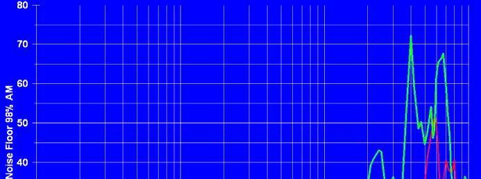
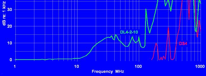
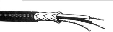
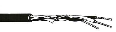
71 Loss in Foil/drain shielded Audio Cables Loss in Braid-shielded Audio Cables 71
72 Digital Equipment Any equipment with digital circuitry, a clock, or a switching power supply can cause RFI as well as receiving it Unlikely to interfere with audio Is likely to interfere with wireless mics Reciprocity In general, shielding and filtering that reduces emissions will also reduce susceptibility Passive networks, shielding, and antennas work in both directions BUT: If impedances on either side are different, they may not work equally in both directions 72
73 Common Bear Traps Watch out for coherent addition RF at multiple inputs will have random phase at each input Detected audio is precisely in phase at multiple inputs (maybe out of polarity) RFI can build by 3 db per doubling 6 db for four inputs 12 db for 16 inputs 15 db for 32 inputs The Biggest Myths Myth: I need a better ground Fact: A connection to earth will almost never reduce noise or RFI, and it will often make it worse, because the ground wire can act as an antenna. Fact: A connection to earth is very important for lightning protection. 73
74 The Biggest Myths Myth: I need a separate audio ground Fact: Separate grounds are unsafe they can kill someone, increase lightning damage, even start a fire. Fact: Separate grounds are more likely to cause problems than to fix them. Fact: For safety, all grounds must be bonded together The Biggest Myths Myth: I can fix these ground loops with a ground lifter Fact: AC ground lifts are unsafe they can kill someone or start a fire. 74


75 Ground Lifts Bad Medicine Breaks equipment ground path Prevents breaker from blowing if chassis becomes hot Can KILL someone Ground Lifts Bad Medicine Breaks equipment ground path Prevents breaker from blowing if chassis becomes hot Can KILL someone 75

76 The Biggest Myths Myth: I need a power conditioner Fact: Dirty power is rarely the cause of hum, buzz, RFI, or bad sound. Fact: The greatest effect of power conditioners is to transfer money from the pocket of the buyer to the pocket of the seller. The Problem with Unbalanced Interfaces mv typical Noise current flows on the shield, and the IR drop is added to the signal. Use a beefy cable shield Minimizes the drop Reduce the noise voltage between the ends of the cable 76
77 For Unbalanced interconnections, shield resistance is important! Shield current (noise) creates IR drop that is added to the signal E NOISE = 20 log (I SHIELD * R SHIELD ) Coaxial cables differ widely Heavy copper braid (8241F) 2.6 Ω /1000 ft Double copper braid (8281) 1.1 Ω /1000 ft Foil/drain shield #22 gauge 16 Ω /1000 ft IR Drop on Cable Noise reduction = 20 log (R 1 /R 2 ) Typical hi-fi cable = 16 ohm/ft Belden 8241F coax = 2.6 ohm/ft 20 log (2.6/16) = -16 db RF noise voltage reduced by 16 db Because detection is square law, detected RF is reduced by 32 db 77
78 Make the Cable Shorter Resistance is proportional to length, so for the same current, Noise reduction = 20 log (L 1 /L 2 ) 20 log (3/6) = -6 db RF noise voltage reduced by 6 db Because detection is square law, detected RF is reduced by 12 db Make the Cable Shorter It may also reduce the antenna current, so RF noise voltage may be reduced by more than 6 db Because detection is square law, detected RF may be reduced by more than 12 db 78
79 Snake Oil and other Bad Medicine AC Ground Lifts can KILL Broken off ground pins Ground lift adapters AC Ground Isolator can KILL Delays breaker operation when a fault occurs Separate ground rods that are not bonded together can KILL Can defeat the equipment ground Make lightning damage more likely Exotic power cords are a waste of money Power Isolation Transformer Diverts noise away from secondary (good) but adds it to safety ground, where it increases leakage currents (bad) 79

80 Power Isolation Transformer Diverts noise away from secondary (good) but adds it to safety ground, where it increases leakage currents (bad) Power Isolation Transformer Use a good one only to establish the technical power system, but not downstream Single Faraday Shield Two Faraday Shields Ralph Morrison, Grounding and Shielding Techniques 80

81 New EMC Connectors Annular ring of capacitors connects shield to shell Low inductance good connection > 1 GHz More continuous shielding Ferrite bead on pin 1 Bead New EMC Connectors Female has same internal construction Additional spring improves shell contact with mating connector 81
82 Parallel resonance is formed between the inductance of pin 1 and the annular capacitors 82

83 Bead Bead lowers frequency and Q of the resonance An Unexpected Side Benefit A band-aid for pin 1 problems! A low inductance capacitive bond from shield to shell makes the right connection The ferrite bead disconnects the shield from the wrong connection But the shells must make good contact on the equipment, and the shell must be bonded to the chassis. 83

84 Benefits of the EMC Connector Better VHF/UHF Shield connection to enclosure Reduces common mode voltage on pins 2 and 3 Fixes VHF/UHF pin 1 problems Removes shield connection from Pin 1 at VHF/UHF Connects the shield to enclosure No Benefit if XL Shells Not Connected to Enclosure inside Equipment this DAT recorder has a serious Pin 1 problem, and Mating XL shells do not make good contact So the EMC connector can t help! 84


85 Pin 1 test for the DAT recorder Acknowledgements Ron Steinberg Neil Muncy David Josephson Dr. Leo Irakliotis Steve Kusiceil Fair-Rite Products 85

86 Excellent EMC Seminars Taught by Henry Ott October 15-17, 2008 Doubletree Inn at San Francisco Airport Details at References Henry Ott, Noise Reduction Techniques in Electronic Systems, Wiley Interscience, 1988 E. C. Snelling, Soft Ferrites, Properties and Applications, CRC Press, 1969 E. C. Snelling and A. D. Giles, Ferrites for Inductors and Transformers, Research Study Press, 1983 Fair-Rite Products Catalog This 200-page catalog is a wealth of product data and applications guidance on practical ferrites. Ferroxcube Catalog and Applications Notes More online from another great manufacturer of ferrites. 86
87 References Noise Susceptibility in Analog and Digital Signal Processing Systems, N. Muncy, JAES, June 1995 Radio Frequency Susceptibility of Capacitor Microphones, Brown/Josephson (AES Preprint 5720) Common Mode to Differential Mode Conversion in Shielded Twisted Pair Cables (Shield Current Induced Noise), Brown/Whitlock (AES Preprint 5747) Testing for Radio Frequency Common Impedance Coupling in Microphones and Other Audio Equipment, J. Brown (AES Preprint 5897) A Novel Method of Testing for Susceptibility of Audio Equipment to Interference from Medium and High Frequency Broadcast Transmitters, J. Brown (AES Preprint 5898) References New Understandings of the Use of Ferrites in the Prevention and Suppression of RF Interference to Audio Systems, J. Brown (AES Preprint 6564) Understanding How Ferrites Can Prevent and Eliminate RF Interference to Audio Systems, J. Brown Self-published tutorial (on my website) A Ham s Guide to RFI, Ferrites, Baluns, and Audio Interfacing, J. Brown Self-published tutorial (on my website) Applications notes, tutorials, and my AES papers are on my website for free download 87
RFI and Ferrites. Jim Brown K9YC Audio Systems Group, Inc. Santa Cruz. Primary Interference Mechanisms
 RFI and Ferrites Jim Brown K9YC Audio Systems Group, Inc. Santa Cruz jim@audiosystemsgroup.com Primary Interference Mechanisms Common-mode noise on signal wiring Pin 1 problems Improper shield termination
Understanding and Eliminating RF Interference
 Understanding and Eliminating RF Interference Jim Brown K9YC Audio Systems Group, Inc. http://audiosystemsgroup.com Basic Interference Mechanisms Audio cables are antennas Pin 1 problems Shield-current-induced
New Understandings of the Use of Ferrites in the Prevention and Suppression of RF Interference to Audio Systems
 New Understandings of the Use of Ferrites in the Prevention and Suppression of RF Interference to Audio Systems Jim Brown Audio Systems Group, Inc. Chicago, IL, 60640 USA jim@audiosystemsgroup.com This
A Ham's Guide to RFI, Ferrites, Baluns, and Audio Interfacing. Chapter 1 Some Fundamentals
 A Ham's Guide to RFI, Ferrites, Baluns, and Audio Interfacing Revision 6 5 Dec 2016 by Jim Brown K9YC http://k9yc.com The basis of this tutorial is a combination of my engineering education, 60 years in
Device Interconnection
 Device Interconnection An important, if less than glamorous, aspect of audio signal handling is the connection of one device to another. Of course, a primary concern is the matching of signal levels and
Common myths, fallacies and misconceptions in Electromagnetic Compatibility and their correction.
 Common myths, fallacies and misconceptions in Electromagnetic Compatibility and their correction. D. A. Weston EMC Consulting Inc 22-3-2010 These are some of the commonly held beliefs about EMC which are
Coaxial Transmitting Chokes. Don t Bother Taking Notes
 Coaxial Transmitting Chokes Jim Brown K9YC Santa Cruz, CA http://audiosystemsgroup.com Don t Bother Taking Notes These slides (and a lot more) are at http://audiosystemsgroup.com\publish.htm 1 Why Do We
Electromagnetic interference at the mains ports of an equipment
 Electromagnetic interference at the mains ports of an equipment Mircea Ion Buzdugan, Horia Bălan, Emil E. Simion, Tudor Ion Buzdugan Technical University from Cluj-Napoca, 15, Constantin Daicoviciu street,
11 Myths of EMI/EMC ORBEL.COM. Exploring common misconceptions and clarifying them. MYTH #1: EMI/EMC is black magic.
 11 Myths of EMI/EMC Exploring common misconceptions and clarifying them By Ed Nakauchi, Technical Consultant, Orbel Corporation What is a myth? A myth is defined as a popular belief or tradition that has
Differential-Mode Emissions
 Differential-Mode Emissions In Fig. 13-5, the primary purpose of the capacitor C F, however, is to filter the full-wave rectified ac line voltage. The filter capacitor is therefore a large-value, high-voltage
Categorized by the type of core on which inductors are wound:
 Inductors Categorized by the type of core on which inductors are wound: air core and magnetic core. The magnetic core inductors can be subdivided depending on whether the core is open or closed. Equivalent
Chokes and Isolation Transformers For Receiving Antennas By Jim Brown K9YC 2018 by James W. Brown All rights reserved
 Chokes and Isolation Transformers For Receiving Antennas By Jim Brown K9YC 2018 by James W. Brown All rights reserved Why We Need Them A feedline must be grounded where it enters the shack-for lightning
A statistical survey of common-mode noise
 A statistical survey of common-mode noise By Jerry Gaboian Characterization Engineer, High Performance Linear Department Introduction In today s high-tech world, one does not have to look very far to find
WHY YOU NEED A CURRENT BALUN
 HF OPERATORS WHY YOU NEED A CURRENT BALUN by John White VA7JW NSARC HF Operators 1 What is a Balun? A BALUN is a device typically inserted at the feed point of a dipole-like antenna wire dipoles, Yagi
EMI AND BEL MAGNETIC ICM
 EMI AND BEL MAGNETIC ICM ABSTRACT Electromagnetic interference (EMI) in a local area network (LAN) system is a common problem that every LAN system designer faces, and it is a growing problem because the
Reducing Motor Drive Radiated Emissions
 Volume 2, Number 2, April, 1996 Application Note 107 Donald E. Fulton Reducing Motor Drive Radiated Emissions Introduction This application note discusses radiated emissions (30 Mhz+) of motor drives and
Locate and minimize those nasty RFI problems while transmitting or receiving on HF or VHF
 RFI in the Ham Shack - Tips and Traps Radio Frequency Interference Locate and minimize those nasty RFI problems while transmitting or receiving on HF or VHF Rick Lapp, KC2FD Typical RFI Problems while
Killing RF Noise for Field Day and CQP. Jim Brown, K9YC
 Killing RF Noise for Field Day and CQP Jim Brown, K9YC The Fundamental Problem RF noise is generated inside equipment The wires inside equipment, and cables that interconnect equipment, are antennas, and
ELECTROMAGNETIC COMPATIBILITY HANDBOOK 1. Chapter 8: Cable Modeling
 ELECTROMAGNETIC COMPATIBILITY HANDBOOK 1 Chapter 8: Cable Modeling Related to the topic in section 8.14, sometimes when an RF transmitter is connected to an unbalanced antenna fed against earth ground
Locating and Killing Receiver Interference. Gary Johnson, NA6O January, 2018
 Locating and Killing Receiver Interference Gary Johnson, NA6O January, 2018 1 Agenda Types of noise and interference Typical noise sources Finding the noise Noise mitigation Your rights per the FCC References
Locate and minimize those nasty RFI problems while transmitting or receiving on HF or VHF
 RFI in the Ham Shack Tips, Tricks and Traps Radio Frequency Interference Locate and minimize those nasty RFI problems while transmitting or receiving on HF or VHF Rick Lapp, KC2FD rick@ricklapp.net Typical
SCIN. Shield Current Induced Noise. Causes and Solutions. Random Thoughts from Chicago
 Random Thoughts from Chicago SCIN Shield Current Induced Noise by Jim Brown Causes and Solutions My last two columns have focused on pin 1 problems as an open door for RF into audio equipment. But RF can
APPLICATION NOTE. System Design for RF Immunity
 APPLICATION NOTE System Design for RF Immunity Audio Codec Application Note Rev1.0 Page 1 of 6 March 2008 With the growth of the portable electronic devices industry, radiated RF fields and potential interference
COAXIAL TRANSMISSION LINE COMMON-MODE CURRENT
 COAXIAL TRANSMISSION LINE COMMON-MODE CURRENT Introduction Coaxial transmission lines are popular for their wide frequency bandwidth and high resistance to electromagnetic interference (EMI). Coax cables
Presented by Joanna Hill
 Santa Clara IEEE EMC Chapter meeting April 9, 2013 Dorothy we're not in Kansas any more, we are in Impedance land. Oh my! Presented by Joanna Hill Cell 248-765-3599 jhill28590@comcast.net Welcome to Impedance
An Introduction to Radio Frequency Interference
 An Introduction to Radio Frequency Interference Ron Hranac, N0IVN Member, ARRL EMC Committee ARRL Colorado Section Technical Specialist What is RFI? RFI is an abbreviation for radio frequency interference
Application of Soft Ferrite Material: from EMC to RFID
 Application of Soft Ferrite Material: from EMC to RFID 26 April 2012 Alan Keenan Industrial Electronics GmbH in partnership with HF Technology & Fair-Rite Products Corp. www.fair-rite.com www.ie4u.eu Topics
MFJ-219/219N 440 MHz UHF SWR Analyzer TABLE OF CONTENTS
 MFJ-219/219N 440 MHz UHF SWR Analyzer TABLE OF CONTENTS Introduction...2 Powering The MFJ-219/219N...3 Battery Installation...3 Operation Of The MFJ-219/219N...4 SWR and the MFJ-219/219N...4 Measuring
Common myths, fallacies and misconceptions in Electromagnetic Compatibility and their correction.
 Common myths, fallacies and misconceptions in Electromagnetic Compatibility and their correction. D. A. Weston EMC Consulting Inc 15-3-2013 1) First topic an introduction These are some of the commonly
Chapter 12 Digital Circuit Radiation. Electromagnetic Compatibility Engineering. by Henry W. Ott
 Chapter 12 Digital Circuit Radiation Electromagnetic Compatibility Engineering by Henry W. Ott Forward Emission control should be treated as a design problem from the start, it should receive the necessary
"Natural" Antennas. Mr. Robert Marcus, PE, NCE Dr. Bruce C. Gabrielson, NCE. Security Engineering Services, Inc. PO Box 550 Chesapeake Beach, MD 20732
 Published and presented: AFCEA TEMPEST Training Course, Burke, VA, 1992 Introduction "Natural" Antennas Mr. Robert Marcus, PE, NCE Dr. Bruce C. Gabrielson, NCE Security Engineering Services, Inc. PO Box
Trees, vegetation, buildings etc.
 EMC Measurements Test Site Locations Open Area (Field) Test Site Obstruction Free Trees, vegetation, buildings etc. Chamber or Screened Room Smaller Equipments Attenuate external fields (about 100dB) External
A Transmatch for Balanced or Unbalanced Lines
 A Transmatch for Balanced or Unbalanced Lines Most modern transmitters are designed to operate into loads of approximately 50 Ω. Solid-state transmitters produce progressively lower output power as the
Top Ten EMC Problems
 Top Ten EMC Problems presented by: Kenneth Wyatt Sr. EMC Consultant EMC & RF Design, Troubleshooting, Consulting & Training 10 Northern Boulevard, Suite 1 Amherst, New Hampshire 03031 +1 603 578 1842 www.silent-solutions.com
Chapter 12: Transmission Lines. EET-223: RF Communication Circuits Walter Lara
 Chapter 12: Transmission Lines EET-223: RF Communication Circuits Walter Lara Introduction A transmission line can be defined as the conductive connections between system elements that carry signal power.
Milton Keynes Amateur Radio Society (MKARS)
") Milton Keynes Amateur Radio Society (MKARS) Intermediate Licence Course Feeders Antennas Matching (Worksheets 31, 32 & 33) MKARS Intermediate Licence Course - Worksheet 31 32 33 Antennas Feeders Matching
Milton Keynes Amateur Radio Society (MKARS) Intermediate Licence Course Feeders Antennas Matching (Worksheets 31, 32 & 33) MKARS Intermediate Licence Course - Worksheet 31 32 33 Antennas Feeders Matching
The design of Ruthroff broadband voltage transformers M. Ehrenfried G8JNJ
 The design of Ruthroff broadband voltage transformers M. Ehrenfried G8JNJ Introduction I started investigating balun construction as a result of various observations I made whilst building HF antennas.
GROUNDING. What is it? Al Lewey K7ABL. Disclaimer
 GROUNDING What is it? Al Lewey K7ABL Disclaimer Disclamier Mechanical Engineer with some electrical background My primary reference is References UP THE TOWER The Complete Guide to Tower Construction By
Application Note # 5438
 Application Note # 5438 Electrical Noise in Motion Control Circuits 1. Origins of Electrical Noise Electrical noise appears in an electrical circuit through one of four routes: a. Impedance (Ground Loop)
Top Ten EMC Problems & EMC Troubleshooting Techniques by Kenneth Wyatt, DVD, Colorado Springs Rev. 1, Feb 26, 2007
 EMC Engineering Top Ten EMC Problems & EMC Troubleshooting Techniques by Kenneth Wyatt, DVD, Colorado Springs Rev. 1, Feb 26, 2007 1a. Ground Impedance The overwhelming majority of high-frequency problems,
The Ins and Outs of Audio Transformers. How to Choose them and How to Use them
 The Ins and Outs of Audio Transformers How to Choose them and How to Use them Steve Hogan Product Development Engineer, Jensen Transformers 1983 1989 Designed new products and provided application assistance
AC Motor Drives EMC Standard Installation Guide EMC Compliance Practice
 http://www.delta.com.tw/industrialautomation/ AC Motor Drives EMC Standard Installation Guide EMC Compliance Practice i Preface When an AC motor drive is installed in a noisy environment, radiated and/or
EMC of Power Converters
 Alain CHAROY - (0033) 4 76 49 76 76 - a.charoy@aemc.fr EMC EMC of Power Converters Friday 9 May 2014 Electromagnetism is just electricity Converters are particularly concerned with EMC: Conducted disturbances
Understanding and Optimizing Electromagnetic Compatibility in Switchmode Power Supplies
 Understanding and Optimizing Electromagnetic Compatibility in Switchmode Power Supplies 1 Definitions EMI = Electro Magnetic Interference EMC = Electro Magnetic Compatibility (No EMI) Three Components
Optimizing Your Stations Performance
 Optimizing Your Stations Performance A few hints / techniques, recommendations for getting the most RF out to the Antenna from your HF, VHF / UHF station. Tonights Presenters: Doug Theriault NO1D John
Overview of the ATLAS Electromagnetic Compatibility Policy
 Overview of the ATLAS Electromagnetic Compatibility Policy G. Blanchot CERN, CH-1211 Geneva 23, Switzerland Georges.Blanchot@cern.ch Abstract The electromagnetic compatibility of ATLAS electronic equipments
Chapter 16 PCB Layout and Stackup
 Chapter 16 PCB Layout and Stackup Electromagnetic Compatibility Engineering by Henry W. Ott Foreword The PCB represents the physical implementation of the schematic. The proper design and layout of a printed
Using Ferrite Beads Keep RF Out of TV Sets, Telephones, VCR's Burglar Alarms and other Electronic Equipment
 Using Ferrite Beads Keep RF Out of TV Sets, Telephones, VCR's Burglar Alarms and other Electronic Equipment RFI and TVI have been with us for a long time. Now we have microwave ovens, VCR's and many other
Solving Electromagnetic Interference (EMI) with Ferrites
 with Ferrites") Solving Electromagnetic Interference (EMI) with Ferrites What are ferrites? How do ferrites help Suppress EMI? How to chose proper ferrite and component Material Characteristics Material and Core Selection
Solving Electromagnetic Interference (EMI) with Ferrites What are ferrites? How do ferrites help Suppress EMI? How to chose proper ferrite and component Material Characteristics Material and Core Selection
Analogue circuit design for RF immunity
 Analogue circuit design for RF immunity By EurIng Keith Armstrong, C.Eng, FIET, SMIEEE, www.cherryclough.com First published in The EMC Journal, Issue 84, September 2009, pp 28-32, www.theemcjournal.com
Jacques Audet VE2AZX. Nov VE2AZX 1
 Jacques Audet VE2AZX VE2AZX@amsat.org Nov. 2006 VE2AZX 1 - REASONS FOR USING A BALUN - TYPES OF BALUNS - CHECK YOUR BALUN WITH AN SWR ANALYZER - MEASURING THE IMPEDANCE OF A NUMBER OF FERRITES - IMPEDANCE
Electro-Magnetic Interference and Electro-Magnetic Compatibility (EMI/EMC)
") INTROUCTION Manufacturers of electrical and electronic equipment regularly submit their products for EMI/EMC testing to ensure regulations on electromagnetic compatibility are met. Inevitably, some equipment
INTROUCTION Manufacturers of electrical and electronic equipment regularly submit their products for EMI/EMC testing to ensure regulations on electromagnetic compatibility are met. Inevitably, some equipment
Objectives of transmission lines
 Introduction to Transmission Lines Applications Telephone Cable TV (CATV, or Community Antenna Television) Broadband network High frequency (RF) circuits, e.g., circuit board, RF circuits, etc. Microwave
HAMTRONICS TB901 FM EXCITER INSTALLATION, OPERATION, & MAINTENANCE
 HAMTRONICS TB901 FM EXCITER INSTALLATION, OPERATION, & MAINTENANCE GENERAL INFORMATION. The TB901 is a single-channel low power fm transmitter (exciter) designed to provide 300-600 milliwatts continuous
Freescale Semiconductor, I
 Order this document by /D Noise Reduction Techniques for Microcontroller-Based Systems By Imad Kobeissi Introduction With today s advancements in semiconductor technology and the push toward faster microcontroller
Common Impedance Shield Coupling
 Common Impedance Shield Coupling When a coaxial cable is used at low frequencies and the shield is grounded at both ends, V R I IN S S The shield serves two functions: 1. the return conductor for the signal;
Electromagnetic Compatibility
 Electromagnetic Compatibility Introduction to EMC International Standards Measurement Setups Emissions Applications for Switch-Mode Power Supplies Filters 1 What is EMC? A system is electromagnetic compatible
ELEC Course Objectives/Proficiencies
 Lecture 1 -- to identify (and list examples of) intentional and unintentional receivers -- to list three (broad) ways of reducing/eliminating interference -- to explain the differences between conducted/radiated
Experiment 5: Grounding and Shielding
 Experiment 5: Grounding and Shielding Power System Hot (Red) Neutral (White) Hot (Black) 115V 115V 230V Ground (Green) Service Entrance Load Enclosure Figure 1 Typical residential or commercial AC power
MFJ-249B HF/VHF SWR ANALYZER
 TABLE OF CONTENTS MFJ-249B... 2 Introduction... 2 Powering The MFJ-249B... 3 Battery Installation... 3 Alkaline Batteries... 3 NiCd Batteries... 4 Power Saving Mode... 4 Operation Of The MFJ-249B...5 SWR
SN W Mono Filterless Class-D Audio Power Amplifier DESCRIPTION FEATURES APPLICATIONS. Typical Application Circuit
 2.6W Mono Filterless Class-D Audio Power Amplifier DESCRIPTION The SN200 is a 2.6W high efficiency filter-free class-d audio power amplifier in a.5 mm.5 mm wafer chip scale package (WCSP) that requires
Class-D Audio Power Amplifiers: PCB Layout For Audio Quality, EMC & Thermal Success (Home Entertainment Devices)
") Class-D Audio Power Amplifiers: PCB Layout For Audio Quality, EMC & Thermal Success (Home Entertainment Devices) Stephen Crump http://e2e.ti.com Audio Power Amplifier Applications Audio and Imaging Products
Class-D Audio Power Amplifiers: PCB Layout For Audio Quality, EMC & Thermal Success (Home Entertainment Devices) Stephen Crump http://e2e.ti.com Audio Power Amplifier Applications Audio and Imaging Products
1 of 11 30/08/2011 8:50 AM
 1 of 11 30/08/2011 8:50 AM All Ferrite Beads Are Not Created Equal - Understanding the Importance of Ferrite Bead Material Behavior August 2010 Written by Chris Burket, TDK Corporation A common scenario:
ROD ANTENNA TESTING Complete article download from: EMI TESTING. Basic RE102 test (2-30 MHz)
") ROD ANTENNA TESTING Complete article download from: http://stevejensenconsultants.com/rod_ant.pdf EMI TESTING Steve Jensen Steve Jensen Consultants Inc. Sept. 26, 2005 Applicable for DO-160 sec. 21 and
ROD ANTENNA TESTING Complete article download from: http://stevejensenconsultants.com/rod_ant.pdf EMI TESTING Steve Jensen Steve Jensen Consultants Inc. Sept. 26, 2005 Applicable for DO-160 sec. 21 and
Choosing and using filters
 Page 1 of 8 Choosing and using filters By Eur Ing Keith Armstrong CEng MIEE MIEEE How does a designer select which filter to use for which application? This article aims to help him or her make these decisions.
Electrical noise in the OR
 Electrical noise in the OR Chris Thompson Senior Staff Specialist Royal Prince Alfred Hospital SYDNEY SOUTH WEST AREA HEALTH SERVICE NSW HEALTH Electrical noise in the OR Root causes Tiny little signals
EFFECT OF SHIELDING ON CABLE RF INGRESS MEASUREMENTS LARRY COHEN
 EFFECT OF SHIELDING ON CABLE RF INGRESS MEASUREMENTS LARRY COHEN OVERVIEW Purpose: Examine the common-mode and differential RF ingress levels of 4-pair UTP, F/UTP, and F/FTP cables at an (RJ45) MDI port
Electronics Interview Questions
 Electronics Interview Questions 1. What is Electronic? The study and use of electrical devices that operate by controlling the flow of electrons or other electrically charged particles. 2. What is communication?
Emerging Standards for EMC Emissions & Immunity
 Emerging Standards for EMC Emissions & Immunity Requirements for Industrial, Scientific, Medical & Information Technology Equipment CE Marking requirements are the path to increased market access Powerful
Design Considerations
 Design Considerations Ferrite beads provide a simple, economical method for attenuating high frequency noise or oscillations. By slipping a bead over a wire, a RF choke or suppressor is produced which
Chapter 2. The Fundamentals of Electronics: A Review
 Chapter 2 The Fundamentals of Electronics: A Review Topics Covered 2-1: Gain, Attenuation, and Decibels 2-2: Tuned Circuits 2-3: Filters 2-4: Fourier Theory 2-1: Gain, Attenuation, and Decibels Most circuits
Experiment 4: Grounding and Shielding
 4-1 Experiment 4: Grounding and Shielding Power System Hot (ed) Neutral (White) Hot (Black) 115V 115V 230V Ground (Green) Service Entrance Load Enclosure Figure 1 Typical residential or commercial AC power
Designing Your EMI Filter
 The Engineer s Guide to Designing Your EMI Filter TABLE OF CONTENTS Introduction Filter Classifications Why Do We Need EMI Filters Filter Configurations 2 2 3 3 How to Determine Which Configuration to
Bob Brehm, AK6R Chief Engineer Palomar-Engineers.com
 Bob Brehm, AK6R Chief Engineer Palomar-Engineers.com IDXC Visalia - April 2018 This presentation available on website Copyright 2013-2018 Palomar Engineers, Inc. Are you the SOURCE of RFI? IT S ALL YOUR
Ferrites for High Frequency Noise Suppression Chapter 9
 TMPST ngineering and Hardware Design Dr. Bruce C. abrielson, NC 1998 Ferrites for High Frequency Noise Suppression Chapter 9 Introduction The drive for higher speed devices and the proliferation of widespread
Bob Brehm, AK6R Chief Engineer Palomar-Engineers.com. PVARC April Copyright 2016 Palomar Engineers, Inc.
 Bob Brehm, AK6R Chief Engineer Palomar-Engineers.com PVARC April 2016 Copyright 2016 Palomar Engineers, Inc. Causing Neighborhood RFI? IT S ALL YOUR FAULT WITH THAT BIG ANTENNA! Receiving RFI from Neighborhood?
Modeling and Simulation of Powertrains for Electric and Hybrid Vehicles
 Modeling and Simulation of Powertrains for Electric and Hybrid Vehicles Dr. Marco KLINGLER PSA Peugeot Citroën Vélizy-Villacoublay, FRANCE marco.klingler@mpsa.com FR-AM-5 Background The automotive context
Pro Audio Eng PAE-Kx33 AC Power Supply
 Pro Audio Eng PAE-Kx33 AC Power Supply for the Elecraft KX3 Transceiver (and others w/ adapter) Owner s Manual Rev 1.5 February 20, 2015 Thank you for purchasing the PAE-Kx33 AC Power Supply. We originally
Bob Brehm, AK6R Chief Engineer Palomar-Engineers.com
 Bob Brehm, AK6R Chief Engineer Palomar-Engineers.com EARS - October 2017 This presentation available on website Copyright 2013-2017 Palomar Engineers, Inc. Are you the SOURCE of RFI? IT S ALL YOUR FAULT
Bob Brehm, AK6R Chief Engineer Palomar-Engineers.com. Copyright 2015 Palomar Engineers, Inc.
 Bob Brehm, AK6R Chief Engineer Palomar-Engineers.com Copyright 2015 Palomar Engineers, Inc. RFI Workshop Objectives Review fundamentals of Common Mode Noise How ferrites work to suppress Common Mode noise
KOLLMORGEN. Motion Technologies Group. EMC Installation and Application Guidelines for BDS4/5 Goldline Series MB4000H Issue 3
 KOLLMORGEN Motion Technologies Group EMC Installation and Application Guidelines for BDS4/5 Goldline Series MB4000H Issue 3 CONTENTS DOCUMENT HISTORY 1 DECLARATION OF CONFORMITY 1 1. INTRODUCTION 2 2.
10 Safety earthing/grounding does not help EMC at RF
 1of 6 series Webinar #3 of 3, August 28, 2013 Grounding, Immunity, Overviews of Emissions and Immunity, and Crosstalk Contents of Webinar #3 Topics 1 through 9 were covered by the previous two webinars
SOME USES FOR RF1,RF5 and VA1 ANALYSTS. SWR Measurement
 SOME USES FOR RF1,RF5 and VA1 ANALYSTS THE HANDIEST INSTRUMENTS IN DECADES! When you put up an antenna in the the old days, it could be a real struggle. The only way to tell if it was tuned to the right
DATA TRANSMISSION. ermtiong. ermtiong
 DATA TRANSMISSION Analog Transmission Analog signal transmitted without regard to content May be analog or digital data Attenuated over distance Use amplifiers to boost signal Also amplifies noise DATA
Balanced Line Driver & Receiver
 Balanced Line Driver & Receiver Rod Elliott (ESP) Introduction Sometimes, you just can't get rid of that %$#*& hum, no matter what you do. Especially with long interconnects (such as to a powered sub-woofer),
150Hz to 1MHz magnetic field coupling to a typical shielded cable above a ground plane configuration
 150Hz to 1MHz magnetic field coupling to a typical shielded cable above a ground plane configuration D. A. Weston Lowfreqcablecoupling.doc 7-9-2005 The data and information contained within this report
Understanding the Importance of Ferrite Bead Material Behavior
 Magazine August 2010 All ferrite beads are not created equal Understanding the Importance of Ferrite Bead Material Behavior by Chris T. Burket, TDK Corporation A common scenario: A design engineer inserts
Using Ferrites for High Frequency Noise Suppression
 Using Ferrites for High Frequency Noise Suppression Bruce C. abrielson, PhD Security ngineering Services PO Box 550, Chesapeake Beach, Maryland 20732 Introduction The drive for higher speed devices and
Measurement and Analysis for Switchmode Power Design
 Measurement and Analysis for Switchmode Power Design Switched Mode Power Supply Measurements AC Input Power measurements Safe operating area Harmonics and compliance Efficiency Switching Transistor Losses
E4-130, E4-250 power amplifier. user manual
 E4-130, E4-250 power amplifier user manual Musikhaus Thomann e.k. Treppendorf 30 96138 Burgebrach Germany Telephone: +49 (0) 9546 9223-0 E-mail: info@thomann.de Internet: www.thomann.de 30.10.2014, ID:
ARNSW Balun Day. Balun construction
 ARNSW Balun Day Balun construction Typical Baluns All built from locally available components. Balun uses Most baluns are used to match the 50Ω output of a transceiver to an antenna. A centre fed dipole
Real-World Balanced Interfaces and Other-World Myths
 PNW Section 24 May 2005 Real-World Balanced Interfaces and Other-World Myths Presented by Bill Whitlock President, Jensen Transformers, Inc. Member, Audio Engineering Society Senior Member, Institute of
ELECTRICAL FILTERS. (Command Control Communications Computer & Intelligence) E 3 LINE FILTERS EMI LEMP NEMP HEMP TEMPEST
 E 3 LINE FILTERS EMI LEMP NEMP HEMP TEMPEST") ELECTRICAL FILTERS INTEGRATED PROTECTION OF C 4 I EQUIPMENT & FACILITIES (Command Control Communications Computer & Intelligence) E 3 LINE FILTERS EMI LEMP NEMP HEMP TEMPEST Electromagnetic Environmental
ELECTRICAL FILTERS INTEGRATED PROTECTION OF C 4 I EQUIPMENT & FACILITIES (Command Control Communications Computer & Intelligence) E 3 LINE FILTERS EMI LEMP NEMP HEMP TEMPEST Electromagnetic Environmental
Understanding the Unintended Antenna Behavior of a Product
 Understanding the Unintended Antenna Behavior of a Product Colin E. Brench Southwest Research Institute Electromagnetic Compatibility Research and Testing colin.brench@swri.org Radiating System Source
Wire Antennas For Limited Space
 Wire Antennas For Limited Space Jim Brown K9YC Santa Cruz, CA http://audiosystemsgroup.com Our Objectives Good Antennas Good efficiency Good predictable patterns Minimal noise pickup and RFI Inexpensive
CHAPTER 8 ANTENNAS 1
 CHAPTER 8 ANTENNAS 1 2 Antennas A good antenna works A bad antenna is a waste of time & money Antenna systems can be very inexpensive and simple They can also be very expensive 3 Antenna Considerations
Improving the immunity of sensitive analogue electronics
 Improving the immunity of sensitive analogue electronics T.P.Jarvis BSc CEng MIEE MIEEE, I.R.Marriott BEng, EMC Journal 1997 Introduction The art of good analogue electronics design has appeared to decline
Practical Tricks with Transformers. Larry Weinstein K0NA
 Practical Tricks with Transformers Larry Weinstein K0NA Practical Tricks with Transformers Quick review of inductance and magnetics Switching inductive loads How many voltages can we get out of a $10 Home
What is an Inductor? Token Electronics Industry Co., Ltd. Version: January 16, Web:
 Version: January 16, 2017 What is an Inductor? Web: www.token.com.tw Email: rfq@token.com.tw Token Electronics Industry Co., Ltd. Taiwan: No.137, Sec. 1, Zhongxing Rd., Wugu District, New Taipei City,
Sound System Interconnection Or: Dealing With Ground Loop Hums
 Sound System Interconnection Or: Dealing With Ground Loop Hums Introduction Rane Technical Staff RaneNote 110 written 1985; last revised 12/2009 This note, originally written in 1985, continues to be one