Measurement and Analysis for Switchmode Power Design
|
|
|
- Buck Peters
- 5 years ago
- Views:
Transcription

1 Measurement and Analysis for Switchmode Power Design

2 Switched Mode Power Supply Measurements AC Input Power measurements Safe operating area Harmonics and compliance Efficiency Switching Transistor Losses Measurement challenges Transformer B-H curve Dynamic Control Loop Step load and start up behavior Output Ripple
3 AC Input Line Power and Harmonics AC In + + DC Out PWM Controller Feedback

4 Line Voltage Line Current Line Power RMS line voltage, RMS line current, real power, apparent power, power factor and crest factor
5 A
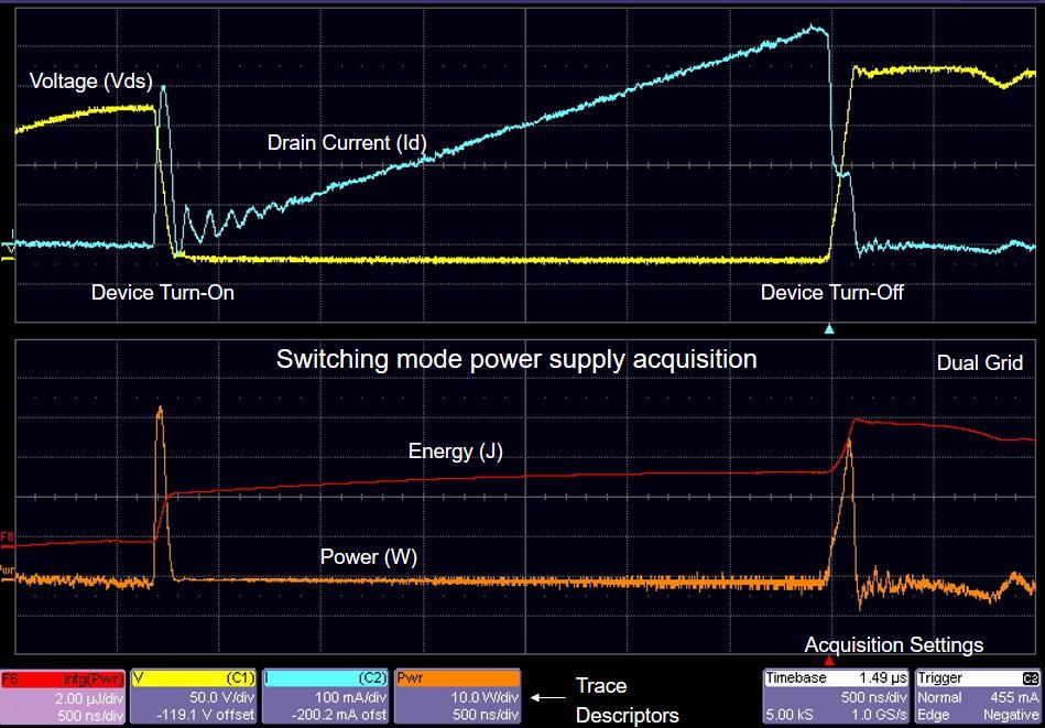
6
7

8 Line Harmonic Analysis Line harmonics can be measured against compliance standards like EN

9 Power supply efficiency measurement


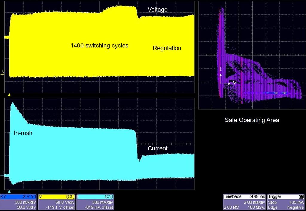
10 Safe Operating Area Mask Testing
11
12 Switched-Mode Power Supply AC In + + DC Out DC AC PWM Controller Feedback The measurements we will talk about here are useful for any inverter based power conversion device

13 Energy Loss Loss displayed in Joules

14 Power Loss Loss displayed in Watts Power = Energy / Time
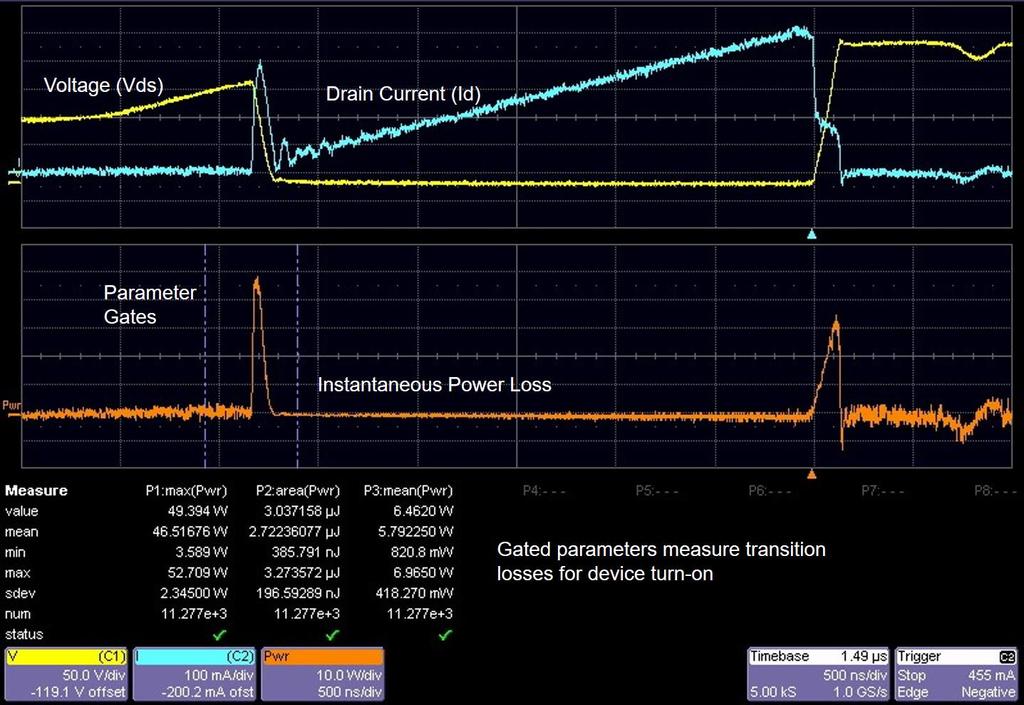
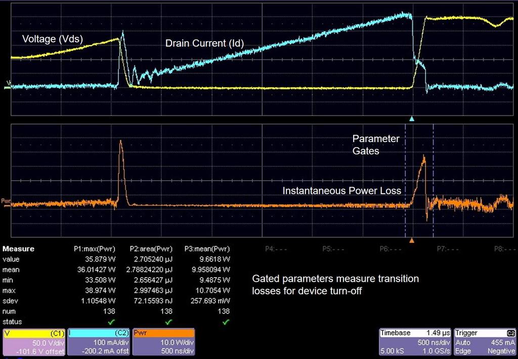
15 Conduction Loss Measurement Challenge Although the peak to peak waveform may be hundreds of volts, during the conduction stage the voltage is close to zero. Measuring the conduction loss or dynamic on resistance is a challenge due to the limited dynamic range of the oscilloscope

16 Current Saturation Voltage Conduction Region Conduction Region Parameter Gate ParameterGate Power Conduction Conduction Generally it is not possible to measure total cycle loss in the same waveform capture. Measurement challenge: Why will this setup produce an incorrect switching loss measurement for the complete switching cycle?
17 The Challenge of Power Measurement Upper V GS measurement required between point A and B +175 Volts A B Output? Volts
18 A Minus B Method Both A & B must be on screen. This determines the maximum sensitivity the oscilloscope can be set at. Limited channel accuracy matching severely limits the ability to Reject (Subtract) the signal that is Common to both A & B. Line Voltage 1 W Shunt Load Circuit Scope remains safely grounded Channel A - Channel B is not adequate when: The Common Mode Voltage >> Voltage Being Measured Because oscilloscope amplifiers and passive probes are not precisely matched for higher frequency gain (or attenuation), CMRR above a few khz will be very low.
19 Ground Referenced Need for Differential Ground referenced measurements upset by alternate ground path low amplitude signals Currents in the ground distribution system result in Ground is not ground syndrome Common problem when using coaxial shunts Noise in the system can be >> signal of interest Moving the ground ground closer to the device will result in an alternate ground path and large circulating currents in the probe ground lead V+ V+ + I I v - I
20 Floating the Scope Floating the scope can result in a shock hazard, damage to the DUT, damage to the scope and poor measurement accuracy. If the reference voltage connected to the probe ground lead is high enough, conductive surfaces of the scope, including the ground leads of other probes can become shock hazards If an insulation fault were to occur in the primary wiring of the scope, it could raise the front panel of the scope to line potential. If the reference voltage is large, there is a possibility of damaging components in the scope power supply or power line filter from the dielectric breakdown. This type of damage may not show up immediately, but appear later even after the scope is returned to grounded operation. The capacitance between the scope case and earth ground can result in damage to the device under test when the probe ground lead loads the circuit with the full capacitance between the scope case and ground. The scope ground is a discharge path for radiated EMI, and with the scope ground severed, radiated EMI from the scope may intefere with the measurement. Measurement corruption can occur when the ground lead inductance acts on the capacitance to ground to create a series LC resonant circuit which resonates with the common mode signal. Because this capacitance is much larger than the scope input C, the resonant frequency is much lower. Thus, when measured with a floating scope, the waveform of a typical upper gate drive signal often has a significant ring which is really not present in the true signal. This measurement distortion is large enough to make many routine measurements, such as upper gate drive, virtually impossible.

 Line")
 Differential Amplifier")
21 Using Differential Amplifiers CMRR 100,000:1 Overdrive recovery <100 ns Differential Amplifier Line voltage at 400 V full scale (with 8-bit resolution) Line voltage waveform crest at 2 V/div (with 8-bit resolution) Differential Amplifier connected to oscilloscope


22 Transition Losses and Conduction Loss Due to the wide dynamic range of voltage, different vertical sensitivities are needed to accurately resolve conduction loss and turn-on/turn-off loss Voltage waveform at 50 V/Div Voltage waveform at 200 mv/div To measure a device s saturation voltage to 100 mv accuracy when the off voltage is 400 V requires 250 ppm measurement capability The signal conditioning must have linear performance far better than required by an 8 bit digital oscilloscope

23 Solution 1: Overdriving the Signal Differential probe response is very slow to stabilize, and never reaches the correct saturation voltage level Differential amplifier response rapidly stabilizes and reaches the correct saturation voltage level Differential Amplifier Differential Probe

24 Using Differential Amplifier for Saturation Measurements CMRR 100,000:1 Overdrive recovery 400 V to 100 mv <100 ns Precision Offset Generator 0.5% DA1855A Differential Amplifier Differential Amplifier connected to oscilloscope
25
26
27 Using High Definition Oscilloscopes 12-Bit Capture 8-Bit Capture

28 Using High Definition Scope with High Accuracy Probes 12-Bit Capture, 1% accuracy Probe 12-Bit Capture, Standard Probe


29 Example Hardware Configuration Voltage and current probes to match the accuracy of HDO scopes High voltage differential probes with high accuracy and high CMRR. Current probes offer high accuracy and low noise. CP030A and CP031A HVD3102 and HVD3106

30 Rds On Resistance Measurement Overdrive recovery of differential amplifier and high resolution oscilloscope combination

31 Eliminating Sources of Error DC Offsets, Deskew Before making detailed device loss measurements, fine adjust to eliminate DC offset errors and scope probe propagation delay differences

32 Two Ways to Fine Adjust Current Probe DC Offset During Off-state, utilize Math integral function and adjust for zero slope Utilize Power Analyzer s automatic calculation of Off-State Losses and fine adjust to zero


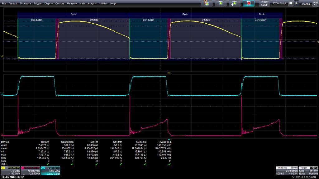
33 Deskewing Voltage and Current Probes Use a deskew calibration source, with V and I coincident edges, to remove propagation delay differences between voltage and current probes Line up the knee of the curve to deskew for power measurement


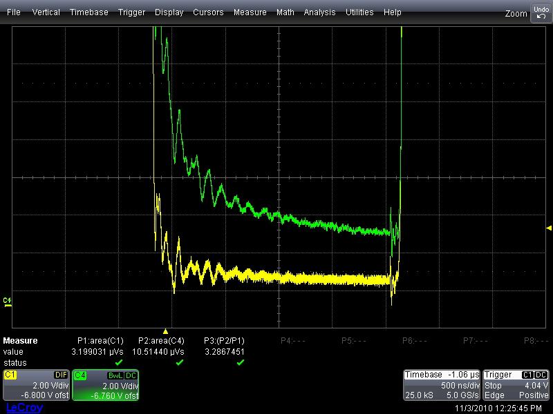
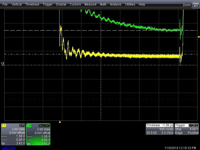
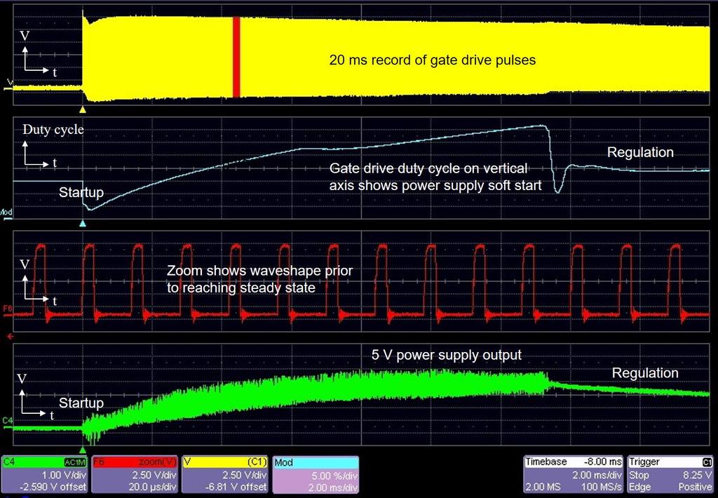
34 Sources of Error Skew Between Voltage and Current Probes Timing skew between voltage and current probes results in measurement error Device turn-off transition loss, V x I, is properly measured at 7.88 uj of energy versus uj without proper deskew
35 Switched-Mode Power Supply AC In + + DC Out PWM Controller Feedback The transformer provides isolation between the power supply input and output

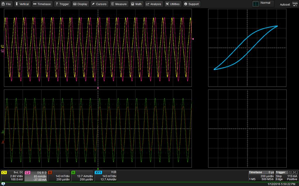
36 Power Analyzer BH Curve

37 Power Analyzer BH Curve
38
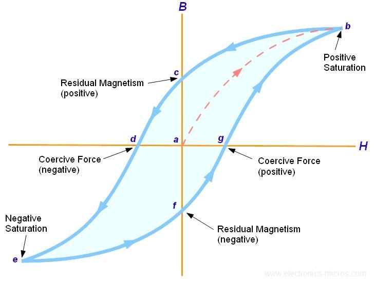
39 BH Curve Definition
40 Voltage Current B= V(t)dt H = ni l B-H Curve shows the hysteresis loop for the magnetic material in inductors and transformers Coil Characteristics Input: # of windings Cross sectional area Magnetic path length Cursor are used to measure magnetic field strength, H, and magnetic flux density, B H is calculated from the current, # windings and magnetic path length B is calculated as the integral of the voltage across the coil Parameter math is utilized for calculation of the magnetic permeability of the material B and H constants are individually entered and the resulting parameter is calculated as B/H

41 Control Loop Measurements AC In + + DC Out PWM Controller Isolated Feedback
42

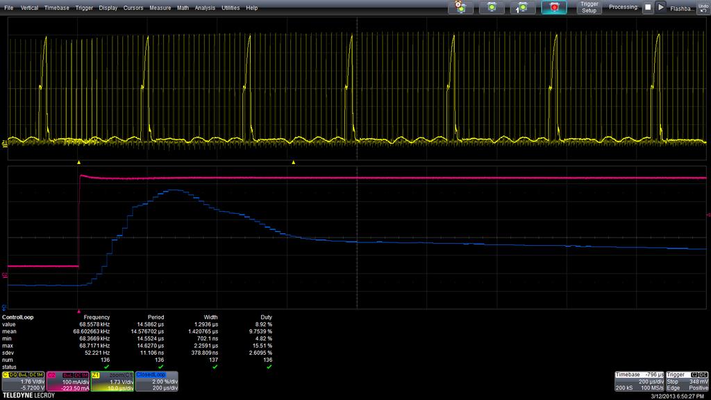
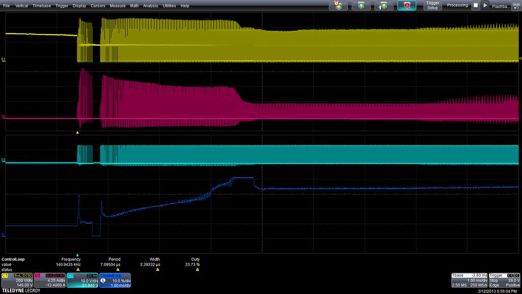
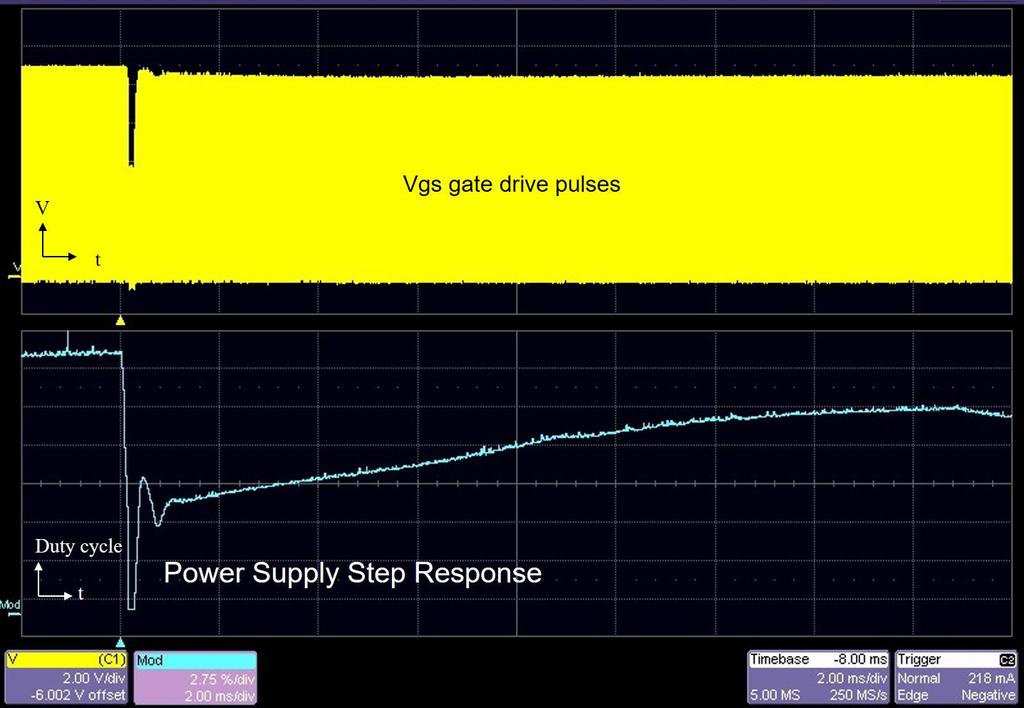
43 Cycle 1 Period Cycle 2 Period Cycle 3 Period Cycle 4 Period Cycle 5 Period Cycle 6 Period Cycle 7 Period Cycle 8 Period Cycle 9 Period Voltage ns ns ns ns ns ns ns ns ns Time Period ns ns ns ns ns ns ns ns ns Time Parameter Track can be used to determine power supply modulation

44 Pulse width begins to decrease Load disconnected Track function plots changing pulse width Settling time
45
46
47
48

49 Control Loop Measurements AC In + + DC Out PWM Controller Isolated Feedback

50 Power supply ripple measurement


51 Radiated Immunity Testing

52 Radiated Immunity Testing - Real Time Functional Performance Evaluation Deviation detection of a device under test (DUT) during exposure to a disturbance Functional state of the DUT is output through non-conductive fiber optic cables Mechanical mode tuner Devices under test are exposed to electric fields high enough to effect operation of nonshielded equipment. Transmit and receive antennas generate a controlled electric field RF-hardened fiber optic transmitters


53 Outside the reverberant chamber, oscilloscope masks test for acceptance criteria Optical receiver and O/E converter 16 channels performing mask test criteria such as signal high level, signal low level, frequency, duty cycle, and other criteria fit within tolerance limits described in the test plan


54 High Voltage Fiber Optically-isolated Probe? Amplifier/Modulating Transmitter A frequency modulating optical transmitter is used for signal and data transmission across a fiber optic cable. Attenuating Tip Accessories Available in a variety of voltage ranges, e.g., +/-1V, +/-5V, +/-20V and +/-40V with a simplified pin socket termination Fiber Optic Cable A standard 1m length cable is provided, but longer ones may be purchased for use. De-modulating Receiver The optical signal is received and de-modulated to an electrical output to the oscilloscope with correct voltage scaling.
55 High Voltage Active Single-ended (Fiber Optic) Probes Parameter Bandwidth Voltage Range (SE) Voltage Range (CM) Loading Attenuation CMRR Value 60 MHz 2 to 80V Virtually Unlimited 1-10MΩ 34-22pF Z IN =50kΩ@100 khz 2x to 80x >140 db A new topology specifically for measuring small signals floating on a HV DC bus
Switched Mode Power Supply Measurements
 Power Analysis 1 Switched Mode Power Supply Measurements AC Input Power measurements Safe operating area Harmonics and compliance Efficiency Switching Transistor Losses Measurement challenges Transformer
High Voltage Differential Probes HVD3605A, HVD3206A HVD310xA
 High Voltage Differential Probes HVD3605A, HVD3206A HVD310xA Key Features 1 kv, 2 kv, 6 kv CAT safety rated models Widest differential voltage ranges available Exceptional common-mode rejection ratio (CMRR)
Today most of engineers use oscilloscope as the preferred measurement tool of choice when it comes to debugging and analyzing switching power
 Today most of engineers use oscilloscope as the preferred measurement tool of choice when it comes to debugging and analyzing switching power supplies. In this session we will learn about some basics of
Power Measurements for Switch-Mode Power Supplies SAVE Verona 2011
 Power Measurements for Switch-Mode Power Supplies SAVE Verona 2011 Agenda Power measurements tools Switch-mode power supplies Automated power measurements Summary Reference information 2 Switch-Mode Power
High Voltage Differential Probes HVD3605, HVD3206 HVD310x
 High Voltage Differential Probes HVD3605, HVD3206 HVD310x Key Features 1 kv, 2 kv, 6 kv CAT safety rated models World s only 1500 Vdc safety rated probe per IEC/EN 61010-031:2015 Widest differential voltage
Probe Considerations for Low Voltage Measurements such as Ripple
 Probe Considerations for Low Voltage Measurements such as Ripple Our thanks to Tektronix for allowing us to reprint the following article. Figure 1. 2X Probe (CH1) and 10X Probe (CH2) Lowest System Vertical
Memo. 1 Summary. 1.1 Introduction. 1.2 Experiments. 1.3 Conclusion
 Topic: Tested: Date: Author: High frequency oscillations measured with high bandwidth current sensors at low current Pearson 2878 and SDN-414 shunts with different resistance values 2014 April 11 th Martin
CONNECTING THE PROBE TO THE TEST INSTRUMENT
 2SHUDWLRQ 2SHUDWLRQ Caution The input circuits in the AP034 Active Differential Probe incorporate components that protect the probe from damage resulting from electrostatic discharge (ESD). Keep in mind
LeCroy PowerMeasure System. Get the Complete Picture
 LeCroy PowerMeasure System Get the Complete Picture Power Measurements Made Easy! COMPLETE PACKAGE! POWER DEVICE ANALYSIS: measures power device saturation voltage, instantaneous power loss, safe operating
IsoVu Optically Isolated DC - 1 GHz Measurement System Offers >120 db CMRR with 2kV Common Mode Range
 IsoVu Optically Isolated DC - 1 GHz Measurement System Offers >120 db CMRR with 2kV Common Mode Range Introduction This white paper describes the optically isolated measurement system architecture trademarked
Techniques to reduce electromagnetic noise produced by wired electronic devices
 Rok / Year: Svazek / Volume: Číslo / Number: Jazyk / Language 2016 18 5 EN Techniques to reduce electromagnetic noise produced by wired electronic devices - Tomáš Chvátal xchvat02@stud.feec.vutbr.cz Faculty
Practical Measurements considerations for GaN and SiC technologies ANDREA VINCI EMEA MARKET DEVELOPMENT MANAGER POWER ELECTRONICS
 Practical Measurements considerations for GaN and SiC technologies ANDREA VINCI EMEA MARKET DEVELOPMENT MANAGER POWER ELECTRONICS PLEASED TO MEET YOU 2 Evolving Test Solutions with Semiconductors WAFER
Power Measurements and Analysis: Challenges and Solutions
 Power Measurements and Analysis: Challenges and Solutions Selu Gupta HW Design Engineer Tektronix, Inc. Beaverton, Oregon USA ABSTRACT: The job of a switch mode power supply and power electronics engineer
9 Specifications. Specifications NOMINAL CHARACTERISTICS
 9 Specifications Specifications NOMINAL CHARACTERISTICS WARRANTED CHARACTERISTICS Nominal characteristics describe parameters and attributes that are guaranteed by design, but do not have associated tolerances.
Understanding and Optimizing Electromagnetic Compatibility in Switchmode Power Supplies
 Understanding and Optimizing Electromagnetic Compatibility in Switchmode Power Supplies 1 Definitions EMI = Electro Magnetic Interference EMC = Electro Magnetic Compatibility (No EMI) Three Components
Experiment 1: Instrument Familiarization (8/28/06)
") Electrical Measurement Issues Experiment 1: Instrument Familiarization (8/28/06) Electrical measurements are only as meaningful as the quality of the measurement techniques and the instrumentation applied
Electrical Measurement Issues Experiment 1: Instrument Familiarization (8/28/06) Electrical measurements are only as meaningful as the quality of the measurement techniques and the instrumentation applied
Experiment 1: Instrument Familiarization
 Electrical Measurement Issues Experiment 1: Instrument Familiarization Electrical measurements are only as meaningful as the quality of the measurement techniques and the instrumentation applied to the
Superior Measurements with a PXI Differential Amplifier
 Superior Measurements with a PXI Differential Amplifier By Adam Fleder, President, TEGAM Why Make a Differential Measurement Making an accurate measurement requires an unbroken chain of signal integrity
Measuring Power Line Impedance
 By Florian Hämmerle & Tobias Schuster 2017 by OMICRON Lab V1.1 Visit www.omicron-lab.com for more information. Contact support@omicron-lab.com for technical support. Page 2 of 13 Table of Contents 1 MEASUREMENT
TT-SI MHz Active Differential Probe
 INSTRUCTION MANUAL TT-SI 9110 100MHz Active Differential Probe These probe is in compliance with EN61010-031:2002+A1:2008 CAT III, Pollution Degree 2 1. Safety Terms and Symbols Terms appear in this manual:
Isolation Addresses Common Sources of Differential Measurement Error
 By Tom Neville A typical measurement system includes an oscilloscope and an oscilloscope probe that provides the connection between the device under test (DUT) and the oscilloscope. Probe selection is
200 ma Output Current High-Speed Amplifier AD8010
 a FEATURES 2 ma of Output Current 9 Load SFDR 54 dbc @ MHz Differential Gain Error.4%, f = 4.43 MHz Differential Phase Error.6, f = 4.43 MHz Maintains Video Specifications Driving Eight Parallel 75 Loads.2%
Trees, vegetation, buildings etc.
 EMC Measurements Test Site Locations Open Area (Field) Test Site Obstruction Free Trees, vegetation, buildings etc. Chamber or Screened Room Smaller Equipments Attenuate external fields (about 100dB) External
TA MHz ±700 V Differential Probe User s Manual. This probe complies with IEC , IEC CAT III, Pollution Degree 2.
 TA041 25 MHz ±700 V Differential Probe User s Manual This probe complies with IEC-1010.1, IEC-1010.2-031 CAT III, Pollution Degree 2. 1. Safety terms and symbols Terms appearing in this manual: WARNING
Conventional Single-Switch Forward Converter Design
 Maxim > Design Support > Technical Documents > Application Notes > Amplifier and Comparator Circuits > APP 3983 Maxim > Design Support > Technical Documents > Application Notes > Power-Supply Circuits
TT-SI 9001 / TT-SI MHz Active Differential Probes
 INSTRUCTION MANUAL TT-SI 9001 / TT-SI 9002 25MHz Active Differential Probes These probes are in compliance with IEC-61010-031 CAT III, Pollution Degree 2 1. Safety Terms and Symbols Terms appear in this
1. High Frequency Performance
 1. High Frequency Performance 1.1. High frequency (-3dB) bandwidth The CWT behaviour at frequencies approaching and exceeding its specified (-3dB) bandwidth is very complicated. It is related to the distributed
Device Interconnection
 Device Interconnection An important, if less than glamorous, aspect of audio signal handling is the connection of one device to another. Of course, a primary concern is the matching of signal levels and
Analogue circuit design for RF immunity
 Analogue circuit design for RF immunity By EurIng Keith Armstrong, C.Eng, FIET, SMIEEE, www.cherryclough.com First published in The EMC Journal, Issue 84, September 2009, pp 28-32, www.theemcjournal.com
TAKE THE MYSTERY OUT OF PROBING. 7 Common Oscilloscope Probing Pitfalls to Avoid
 TAKE THE MYSTERY OUT OF PROBING 7 Common Oscilloscope Probing Pitfalls to Avoid Introduction Understanding common probing pitfalls and how to avoid them is crucial in making better measurements. In an
 1 of 6 03/12/2012 14:56 2012-12-03 HAMEG > Products > Accessories > Probes http://www.hameg.com/186.0.html P R O B E S H Z 5 6-2 * AC/ DC Current Clamps This AC/DC Current Probe is used to measure currents
PDN Probes. P2100A/P2101A Data Sheet. 1-Port and 2-Port 50 ohm Passive Probes
 P2100A/P2101A Data Sheet PDN Probes 1-Port and 2-Port 50 ohm Passive Probes power integrity PDN impedance testing ripple PCB resonances transient step load stability and NISM noise TDT/TDR clock jitter
Saturation of Active Loop Antennas
 Saturation of Active Loop Antennas Alexander Kriz EMC and Optics Seibersdorf Laboratories 2444 Seibersdorf, Austria Abstract The EMC community is working towards shorter test distances for radiated emission
OVP 2:1. Wide Range. Protection
 10W, Wide Input Range DIP, Single & Dual Output DC/DC s Key Features High Efficiency up to 88 10 Isolation MTBF > 1,000,000 Hours 2:1 Wide Input Range CSA9-1 Safety Approval Complies with EN522 Class A
Specify Gain and Phase Margins on All Your Loops
 Keywords Venable, frequency response analyzer, power supply, gain and phase margins, feedback loop, open-loop gain, output capacitance, stability margins, oscillator, power electronics circuits, voltmeter,
Testing Power Factor Correction Circuits For Stability
 Keywords Venable, frequency response analyzer, impedance, injection transformer, oscillator, feedback loop, Bode Plot, power supply design, switching power supply, PFC, boost converter, flyback converter,
Measuring Power Supply Switching Loss with an Oscilloscope
 Measuring Power Supply Switching Loss with an Oscilloscope Our thanks to Tektronix for allowing us to reprint the following. Ideally, the switching device is either on or off like a light switch, and instantaneously
High Speed BUFFER AMPLIFIER
 High Speed BUFFER AMPLIFIER FEATURES WIDE BANDWIDTH: MHz HIGH SLEW RATE: V/µs HIGH OUTPUT CURRENT: 1mA LOW OFFSET VOLTAGE: 1.mV REPLACES HA-33 IMPROVED PERFORMANCE/PRICE: LH33, LTC11, HS APPLICATIONS OP
MODEL 9041 EXTENDED SPECIFICATIONS. 25ppm TRANSPORTABLE CALIBRATOR
 MODEL 9041 EXTENDED SPECIFICATIONS 25ppm TRANSPORTABLE CALIBRATOR 9041 EXTENDED SPECIFICATIONS General Specifications TRANSMILLE LTD Warm Up Time Double the time since last used up to 20 minutes maximum
CHAPTER 2 A SERIES PARALLEL RESONANT CONVERTER WITH OPEN LOOP CONTROL
 14 CHAPTER 2 A SERIES PARALLEL RESONANT CONVERTER WITH OPEN LOOP CONTROL 2.1 INTRODUCTION Power electronics devices have many advantages over the traditional power devices in many aspects such as converting
Probing for oscilloscope
 Probing for oscilloscope Agenda - Notion de sonde en oscilloscopie - Structure des différentes sondes - Passives - Actives - Logiques - Différentielles - Comment choisir la bonne sonde - Nouvelle technologie
MODEL 9050 EXTENDED SPECIFICATIONS. 50ppm TRANSPORTABLE CALIBRATOR
 MODEL 9050 EXTENDED SPECIFICATIONS Ü 50ppm TRANSPORTABLE CALIBRATOR 9050A EXTENDED SPECIFICATIONS General Specifications TRANSMILLE LTD Warm Up Time Double the time since last used up to 20 minutes maximum
Sophisticated Power Loss Analysis Using A Digital Phosphor Oscilloscope
 Sophisticated Power Loss Analysis Using A Digital Phosphor Oscilloscope Quickly Locate Power Dissipation in Switching Power Supplies With demand for power driving architectural changes to switching power
Op-Amp Simulation Part II
 Op-Amp Simulation Part II EE/CS 5720/6720 This assignment continues the simulation and characterization of a simple operational amplifier. Turn in a copy of this assignment with answers in the appropriate
TT-SI MHz DIFFERENTIAL PROBE
 TT-SI 9110 100MHz DIFFERENTIAL PROBE USER S MANUAL This probe is in compliance with IEC-1010.1, IEC - 1010. 2-031 CATⅢ, Pollution Degree 2. 1. Safety Terms and Symbols Terms appear in this manual: WARNING.
Electromagnetic Compatibility
 Electromagnetic Compatibility Introduction to EMC International Standards Measurement Setups Emissions Applications for Switch-Mode Power Supplies Filters 1 What is EMC? A system is electromagnetic compatible
CS101. Conducted Susceptibility CS101. CS101 Maximum Current. CS101 Limits. Basis For CS101 Limits. Comparison To MIL-STD Vdc or Less
 Conducted Susceptibility CS1 Raymond K. Adams Fischer Custom Communications, Inc. 20603 Earl Street Torrance, CA 90503 (3)303-3300 radams@fischercc.com CS1 Applicability DC and AC Input Power Leads Does
Appendix A: Specifications
 All specifications apply to the TDS 200-Series Digital Oscilloscopes and a P2100 probe with the Attenuation switch set to 10X unless noted otherwise. To meet specifications, two conditions must first be
TA MHz ±30 V Differential Probe User s Manual. This probe complies with IEC , IEC CAT I, Pollution Degree 2.
 TA046 800 MHz ±30 V Differential Probe User s Manual This probe complies with IEC-1010.1, IEC-1010.2-031 CAT I, Pollution Degree 2. 1. Safety terms and symbols Terms appearing in this manual: WARNING Warning
External Drive Hardware
 US1086e_External Drive Hardware, 08/2010 External Drive Hardware Selection and Application Answers Answers to external hardware questions A soup to nuts list of questions with installation / application
Vishay Siliconix AN724 Designing A High-Frequency, Self-Resonant Reset Forward DC/DC For Telecom Using Si9118/9 PWM/PSM Controller.
 AN724 Designing A High-Frequency, Self-Resonant Reset Forward DC/DC For Telecom Using Si9118/9 PWM/PSM Controller by Thong Huynh FEATURES Fixed Telecom Input Voltage Range: 30 V to 80 V 5-V Output Voltage,
P a g e 1 ST985. TDR Cable Analyzer Instruction Manual. Analog Arts Inc.
 P a g e 1 ST985 TDR Cable Analyzer Instruction Manual Analog Arts Inc. www.analogarts.com P a g e 2 Contents Software Installation... 4 Specifications... 4 Handling Precautions... 4 Operation Instruction...
Single Supply, Rail to Rail Low Power FET-Input Op Amp AD820
 a FEATURES True Single Supply Operation Output Swings Rail-to-Rail Input Voltage Range Extends Below Ground Single Supply Capability from + V to + V Dual Supply Capability from. V to 8 V Excellent Load
ECE3204 D2015 Lab 1. See suggested breadboard configuration on following page!
 ECE3204 D2015 Lab 1 The Operational Amplifier: Inverting and Non-inverting Gain Configurations Gain-Bandwidth Product Relationship Frequency Response Limitation Transfer Function Measurement DC Errors
CHAPTER 4 MEASUREMENT OF NOISE SOURCE IMPEDANCE
 69 CHAPTER 4 MEASUREMENT OF NOISE SOURCE IMPEDANCE 4.1 INTRODUCTION EMI filter performance depends on the noise source impedance of the circuit and the noise load impedance at the test site. The noise
Reduce Load Capacitance in Noise-Sensitive, High-Transient Applications, through Implementation of Active Filtering
 WHITE PAPER Reduce Load Capacitance in Noise-Sensitive, High-Transient Applications, through Implementation of Active Filtering Written by: Chester Firek, Product Marketing Manager and Bob Kent, Applications
Impact of the Output Capacitor Selection on Switching DCDC Noise Performance
 Impact of the Output Capacitor Selection on Switching DCDC Noise Performance I. Introduction Most peripheries in portable electronics today tend to systematically employ high efficiency Switched Mode Power
results at the output, disrupting safe, precise measurements.
 H Common-Mode Noise: Sources and Solutions Application Note 1043 Introduction Circuit designers often encounter the adverse effects of commonmode noise on a design. Once a common-mode problem is identified,
ELC224 Final Review (12/10/2009) Name:
 Name:") ELC224 Final Review (12/10/2009) Name: Select the correct answer to the problems 1 through 20. 1. A common-emitter amplifier that uses direct coupling is an example of a dc amplifier. 2. The frequency
ELC224 Final Review (12/10/2009) Name: Select the correct answer to the problems 1 through 20. 1. A common-emitter amplifier that uses direct coupling is an example of a dc amplifier. 2. The frequency
Differential Amplifiers
 Differential Amplifiers Benefits of Differential Signal Processing The Benefits Become Apparent when Trying to get the Most Speed and/or Resolution out of a Design Avoid Grounding/Return Noise Problems
TA MHz x10/x100 Differential Probe User s Manual. This probe complies with IEC , IEC CAT III, Pollution Degree 2.
 TA043 100 MHz x10/x100 Differential Probe User s Manual This probe complies with IEC-1010.1, IEC-1010.2 031 CAT III, Pollution Degree 2. 1. Safety terms and symbols Terms appearing in this manual: WARNING
MIC2296. General Description. Features. Applications. High Power Density 1.2A Boost Regulator
 High Power Density 1.2A Boost Regulator General Description The is a 600kHz, PWM dc/dc boost switching regulator available in a 2mm x 2mm MLF package option. High power density is achieved with the s internal
Application Note 5121
 Isolation Amplifiers and Hall-Effect Device For Motor Control Current Sensing Applications Application Note 5121 Introduction Current Sensor is an essential component in a motor control system. Recent
FEATURES TYPICAL APPLICATIO. LT1194 Video Difference Amplifier DESCRIPTIO APPLICATIO S
 FEATURES Differential or Single-Ended Gain Block: ± (db) db Bandwidth: MHz Slew Rate: /µs Low Cost Output Current: ±ma Settling Time: ns to.% CMRR at MHz: db Differential Gain Error:.% Differential Phase
Using X-Y Displays APPLICATION BRIEF LAB WM312. May 29, Introduction. Summary
 Using X-Y Displays APPLICATION BRIEF LAB WM312 May 29, 2012 Summary X-Y Displays or cross plots provide a means of plotting one trace against another. This display mode finds many classical and current
TT-SI MHz Active Differential Probe
 INSTRUCTION MANUAL TT-SI 9101 100MHz Active Differential Probe These probe is in compliance with IEC-61010-031 CAT III, Pollution Degree 2 1. Safety Terms and Symbols Terms appear in this manual: WARNING.
Power Supply Measurement and Analysis Primer
 Power Supply Measurement and Analysis Primer Our thanks to Tektronix for allowing us to reprint the following article. Introduction A power supply is a component, subsystem, or system that converts electrical
Multi-function Gain-Phase Analyzer (Frequency Response Analyzer) Model 2505
 Model 2505") OTHER PRODUCTS.. Multi-function Gain-Phase Analyzer ( Response Analyzer) Model 2505 Standard Configurations Gain phase analyzer response analyzer Phase Angle Voltmeter (PAV) Fast dual channel wide-band
OTHER PRODUCTS.. Multi-function Gain-Phase Analyzer ( Response Analyzer) Model 2505 Standard Configurations Gain phase analyzer response analyzer Phase Angle Voltmeter (PAV) Fast dual channel wide-band
LM6118/LM6218 Fast Settling Dual Operational Amplifiers
 Fast Settling Dual Operational Amplifiers General Description The LM6118/LM6218 are monolithic fast-settling unity-gain-compensated dual operational amplifiers with ±20 ma output drive capability. The
KM4110/KM mA, Low Cost, +2.7V & +5V, 75MHz Rail-to-Rail Amplifiers
 + + www.fairchildsemi.com KM411/KM41.5mA, Low Cost, +.7V & +5V, 75MHz Rail-to-Rail Amplifiers Features 55µA supply current 75MHz bandwidth Power down to I s = 33µA (KM41) Fully specified at +.7V and +5V
MD 200A High voltage differential probe
 1 MD 200A High voltage differential probe User Manual 601-265B MD 200A High voltage differential probe User Manual MD 200A high voltage differential probe contents 1 Safety terms and symbols 5 2 Safety
For ultra-high precision measurement of current: DC, AC, pulsed..., with galvanic separation between primary and secondary. Applications.
 Current Transducer IT 200-S ULTRASTAB I PM = 200 A For ultra-high precision measurement of current: DC, AC, pulsed..., with galvanic separation between primary and secondary. Features Closed loop (compensated)
TRANSMILLE 3010A PRECISION MULTIPRODUCT CALIBRATOR EXTENDED SPECIFICATIONS
 TRANSMILLE 3010A PRECISION MULTIPRODUCT CALIBRATOR EXTENDED SPECIFICATIONS www. transmille.com 3010A EXTENDED SPECIFICATIONS General Specifications TRANSMILLE LTD Warm Up Time Double the time since last
HA MHz, High Slew Rate, High Output Current Buffer. Description. Features. Applications. Ordering Information. Pinouts.
 SEMICONDUCTOR HA-2 November 99 Features Voltage Gain...............................99 High Input Impedance.................... kω Low Output Impedance....................... Ω Very High Slew Rate....................
Guide Version Five techniques for fast, accurate power integrity measurements
 Guide Version 01.00 Five techniques for fast, accurate power integrity measurements Rail voltages are getting smaller, and tolerances are decreasing. As a result, making accurate power rail measurements
CONTENTS. Chapter 1. Introduction to Power Conversion 1. Basso_FM.qxd 11/20/07 8:39 PM Page v. Foreword xiii Preface xv Nomenclature
 Basso_FM.qxd 11/20/07 8:39 PM Page v Foreword xiii Preface xv Nomenclature xvii Chapter 1. Introduction to Power Conversion 1 1.1. Do You Really Need to Simulate? / 1 1.2. What You Will Find in the Following
Model Operating Manual
 Model 7500 DC to 1MHz Wideband Power Amplifier Operating Manual Copyright 2004. All rights reserved. Contents of this publication may not be reproduced in any form without the written permission of Krohn-Hite
N acquisitions, all channels simultaneously, N is selectable from 4, 16, 64, and 128 Inputs
 With compliments All specifications apply to the TDS 200-Series Digital Real-Time Oscilloscope with a P2100 probe with the Attenuation switch set to 10X unless noted otherwise. To meet specifications,
Single Supply, Low Power Triple Video Amplifier AD813
 a FEATURES Low Cost Three Video Amplifiers in One Package Optimized for Driving Cables in Video Systems Excellent Video Specifications (R L = 15 ) Gain Flatness.1 db to 5 MHz.3% Differential Gain Error.6
EMI Filters Demystified. By William R. Bill Limburg February 21, 2018 Phoenix Chapter, IEEE EMC Society
 EMI Filters Demystified By William R. Bill Limburg February 21, 2018 Phoenix Chapter, IEEE EMC Society An EMI Filter Defined An EMI filter is a network designed to prevent unwanted electrical conducted
OPERATIONAL AMPLIFIER PREPARED BY, PROF. CHIRAG H. RAVAL ASSISTANT PROFESSOR NIRMA UNIVRSITY
 OPERATIONAL AMPLIFIER PREPARED BY, PROF. CHIRAG H. RAVAL ASSISTANT PROFESSOR NIRMA UNIVRSITY INTRODUCTION Op-Amp means Operational Amplifier. Operational stands for mathematical operation like addition,
ECEN 474/704 Lab 6: Differential Pairs
 ECEN 474/704 Lab 6: Differential Pairs Objective Design, simulate and layout various differential pairs used in different types of differential amplifiers such as operational transconductance amplifiers
MIW3000 Series EMI. 5-6W, Wide Input Range DIP, Single & Dual Output DC/DC Converters MINMAX. Block Diagram. Key Features
 -6W, Wide Input Range DIP, Single & DC/DC s Key Features Efficiency up to 10 Isolation MTBF > 1,000,000 Hours 2:1 Wide Input Range UL19 Safety Approval Complies with EN22 Class A Temperature Performance
DECLARATION OF CONFORMITY
 DECLARATION OF CONFORMITY Manufacturer's Name: Transmille Ltd. Manufacturer's Address: Unit 4, Select Business Centre Lodge Road Staplehurst TN12 0QW. United Kingdom. Declares, that the product Product
Keysight Technologies How to Make the Best Switch Mode Power Supply Measurements. Application Note
 Keysight Technologies How to Make the Best Switch Mode Power Supply Measurements Application Note Introduction Characterizing the operation of switch mode power supplies requires a broad range of measurements.
The Causes and Impact of EMI in Power Systems; Part 1. Chris Swartz
 The Causes and Impact of EMI in Power Systems; Part Chris Swartz Agenda Welcome and thank you for attending. Today I hope I can provide a overall better understanding of the origin of conducted EMI in
University of New Hampshire InterOperability Laboratory Gigabit Ethernet Consortium
 University of New Hampshire InterOperability Laboratory Gigabit Ethernet Consortium As of June 18 th, 2003 the Gigabit Ethernet Consortium Clause 40 Physical Medium Attachment Conformance Test Suite Version
For ultra-high precision measurement of current: DC, AC, pulsed..., with galvanic separation between primary and secondary. Applications.
 Current Transducer IT 205-S ULTRASTAB I PN = 200 A For ultra-high precision measurement of current: DC, AC, pulsed..., with galvanic separation between primary and secondary. Features Wide operating temperature
University of Pittsburgh
 University of Pittsburgh Experiment #1 Lab Report Frequency Response of Operational Amplifiers Submission Date: 05/29/2018 Instructors: Dr. Ahmed Dallal Shangqian Gao Submitted By: Nick Haver & Alex Williams
Investigation of a Voltage Probe in Microstrip Technology
 Investigation of a Voltage Probe in Microstrip Technology (Specifically in 7-tesla MRI System) By : Mona ParsaMoghadam Supervisor : Prof. Dr. Ing- Klaus Solbach April 2015 Introduction - Thesis work scope
Transformer Waveforms
 OBJECTIVE EXPERIMENT Transformer Waveforms Steady-State Testing and Performance of Single-Phase Transformers Waveforms The voltage regulation and efficiency of a distribution system are affected by the
Manual Supplement. This supplement contains information necessary to ensure the accuracy of the above manual.
 Manual Title: 550A Getting Started Supplement Issue: Part Number: 415509 Issue Date: 9/18 Print Date: November 01 Page Count: 19 Revision/Date: This supplement contains information necessary to ensure
EMC Pulse Measurements
 EMC Pulse Measurements and Custom Thresholding Presented to the Long Island/NY IEEE Electromagnetic Compatibility and Instrumentation & Measurement Societies - May 13, 2008 Surge ESD EFT Contents EMC measurement
Operator s Manual. DA1855A Differential Amplifier
 Operator s Manual DA1855A Differential Amplifier DA1855A Differential Amplifier Operator s Manual February, 2018 2018 Teledyne LeCroy, Inc. All rights reserved. Unauthorized duplication of Teledyne LeCroy
Fluke 192/196/199. ScopeMeter. Users Manual
 Fluke 192/196/199 ScopeMeter Users Manual 4822 872 00983 October 2000, Rev.2, 2/01 2000 Fluke Corporation. All rights reserved. Printed in the Netherlands. All product names are trademarks of their respective
Testing and Verification Waveforms of a Small DRSSTC. Part 1. Steven Ward. 6/24/2009
 Testing and Verification Waveforms of a Small DRSSTC Part 1 Steven Ward www.stevehv.4hv.org 6/24/2009 Power electronics, unlike other areas of electronics, can be extremely critical of small details, since
Quick Start RSDPB5000/RSDPB4000. High Voltage Differential Probe Series
 Quick Start RSDPB5000/RSDPB4000 High Voltage Differential Probe Series 2 Please read this manual carefully before use Safety precautions 1. Be cautious of an electric shock 2. Pay attention to the maximum
New Technique Accurately Measures Low-Frequency Distortion To <-130 dbc Levels by Xavier Ramus, Applications Engineer, Texas Instruments Incorporated
 New Technique Accurately Measures Low-Frequency Distortion To
INVESTIGATION AND DESIGN OF HIGH CURRENT SOURCES FOR B-H LOOP MEASUREMENTS
 INVESTIGATION AND DESIGN OF HIGH CURRENT SOURCES FOR B-H LOOP MEASUREMENTS Boyanka Marinova Nikolova, Georgi Todorov Nikolov Faculty of Electronics and Technologies, Technical University of Sofia, Studenstki
For ultra-high precision measurement of current: DC, AC, pulsed..., with galvanic separation between primary and secondary. Applications.
 Current Transducer IT 700-S ULTRASTAB I PM = 700 A For ultra-high precision measurement of current: DC, AC, pulsed..., with galvanic separation between primary and secondary. Features Closed loop (compensated)