S-Parameters Simulation
|
|
|
- Kristopher Barnaby George
- 5 years ago
- Views:
Transcription
1


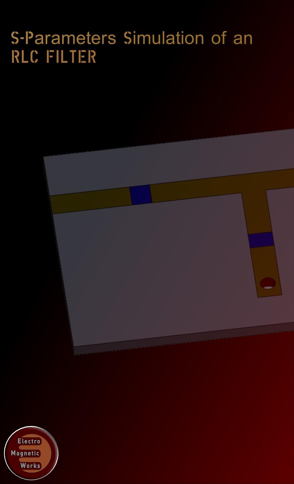
2 S-Parameters Simulation of an RLC filter Description An RLC circuit is an electrical circuit formed of a number of resistors, inductors and capacitors. There are multiple applications for this type of circuits. Some of the most important ones are oscillators, tuners of radio receivers and television sets and of course filters. RLC circuits are used to create band- pass and band-stop filters as well. The RLC filter is normally called a second order circuit which means that the circuit parameters such as voltage and current in can be described by a differential equation of second-order. A problem that occurs in designing such filters is the resistance shown by the inductor. As the inductors are fabricated by coils of wires they do have an undesirable resistance that could have a significant effect on the performance of the circuit. That is why it is always a good idea to do a field analysis of such configurations during the design. HFWorks enables the designer of simulating such circuits either by specifying the values of the lumped elements used in the circuits or by modeling the actual coil. This tutorial focuses on an RLC filter made up of lumped elements, along with microstrip lines, profiting of HFWorks ability to mix both types of simulations: circuit and 3D models together in a single study. The band-pass filter operates at 1 GHz with a bandwidth of 10%. Figure 1: 3D view of an RLC filter Simulation To simulate the behavior of this filter (insertion and return loss at the desired frequency band, input and output matching), we will create a scattering parameters study, and specify the relevant frequency band at which the filter operates (in our case 21 frequencies uniformly distributed from 1.8 GHz to 3.8 GHz). The simulated study provides multiple choices and options to plot and to adjust the outputted results according to the user s need. They also offer the exploitation of electrical parameters calculated in Scattering parameters simulations (insertion, return losses...etc).


 and the air box.")
3 Solids and Materials HFWORKS APPLICATION The microstrip lines (conductor and ground metals) are supposed to be perfect electric conductors built on a Mat1 substrate. RLC components are modeled on three shields and they have been chosen the following inductance and capacitance values: 127 nh and 0.2 pf respectively for the shields close to ports. The parallel shield has these values: nh and 34.9 pf being implemented as parallel RLC circuit. Meshing Since the signal s path implicate port and the in signal surfaces, the mesh has to be concentrated on these parts. Meshing these surfaces helps the solver refine its precision on the eddy parts, and take the path s shape into account Boundary conditions The ports are applied to the lateral faces of the substrate (the sides of the horizontal microstrip line with the two RLC shields) and the air box. This way, the simulation considers the electric field s distribution in the air and the radiation boundaries would give results more conveniently to quasi-tem theory of waves transmission over a microstrip line. Figure 2: Mesh of the dipole antenna


4 Results Various 3D and 2D plots are available to exploit, depending on the nature of the task and on which parameter the user is interested in. As we are dealing with a filter simulation, plotting the insertion and return losses sounds like an intuitive task. The following figure shows both the insertion and return losses of the considered filter: Figure 3: Insertion and return loss of the filter around 1 GHz The insertion loss appears to be very low within the frequency band around 1 GHz and gives great isolation below 0.94 GHz and above 1.06 GHz. Plotting the return loss on a Smith chart plot is more relevant when we deal with matching issues. For this purpose, the following figure illustrates the S11 curve along with a red marker showing the return loss at 1 GHz.

 634 9797 www.emworks.")
5 The electric field distribution at 1 GHz has been spotted on the following figure, we can see clearly that wave goes through the circuit and reaches the second port Figure 5: Electric field vector distribution on the circuit at the aimed frequency (1 GHz and 0.83 GHz) ElectroMagneticWorks Inc St-Patrick, Suite 300, H8N 2H1, Lasalle, Qc, Canada +1 (514) ElectroMagnetic Design Made Easy Powered By SolidWorks 2012 ElectroMagneticWorks, Inc. All Rights Reserved.
ELC 4396 RF/Microwave Circuits I Fall 2011 Final Exam December 9, 2011 Open Book/Open Notes 2 hours
 Name ELC 4396 RF/Microwave Circuits I Fall 2011 Final Exam December 9, 2011 Open Book/Open Notes 2 hours 1. The exam is open-book/open-notes. 2. A calculator may be used to assist with the test. No laptops
ECEN 4634/5634, MICROWAVE AND RF LABORATORY
 ECEN 4634/5634, MICROWAVE AND RF LABORATORY Final Exam December 18, 2017 7:30-10:00pm 150 minutes, closed book, 1 sheet allowed, no calculators (estimates need to be within 3dB) Part 1 (60%). Briefly answer
Waveguides. Metal Waveguides. Dielectric Waveguides
 Waveguides Waveguides, like transmission lines, are structures used to guide electromagnetic waves from point to point. However, the fundamental characteristics of waveguide and transmission line waves
Physical RF Circuit Techniques and Their Implications on Future Power Module and Power Electronic Design
 Physical RF Circuit Techniques and Their Implications on Future Power Module and Power Electronic Design Adam Morgan 5-5-2015 NE IMAPS Symposium 2015 Overall Motivation Wide Bandgap (WBG) semiconductor
APPLIED ELECTROMAGNETICS: EARLY TRANSMISSION LINES APPROACH
 APPLIED ELECTROMAGNETICS: EARLY TRANSMISSION LINES APPROACH STUART M. WENTWORTH Auburn University IICENTBN Nlfll 1807; WILEY 2 OO 7 ; Ttt^TlLtftiTTu CONTENTS CHAPTER1 Introduction 1 1.1 1.2 1.3 1.4 1.5
A COMPACT DUAL-BAND POWER DIVIDER USING PLANAR ARTIFICIAL TRANSMISSION LINES FOR GSM/DCS APPLICATIONS
 Progress In Electromagnetics Research Letters, Vol. 1, 185 191, 29 A COMPACT DUAL-BAND POWER DIVIDER USING PLANAR ARTIFICIAL TRANSMISSION LINES FOR GSM/DCS APPLICATIONS T. Yang, C. Liu, L. Yan, and K.
CHAPTER 5 PRINTED FLARED DIPOLE ANTENNA
 CHAPTER 5 PRINTED FLARED DIPOLE ANTENNA 5.1 INTRODUCTION This chapter deals with the design of L-band printed dipole antenna (operating frequency of 1060 MHz). A study is carried out to obtain 40 % impedance
RF AND MICROWAVE ENGINEERING
 RF AND MICROWAVE ENGINEERING FUNDAMENTALS OF WIRELESS COMMUNICATIONS Frank Gustrau Dortmund University of Applied Sciences and Arts, Germany WILEY A John Wiley & Sons, Ltd., Publication Preface List of
Methodology for MMIC Layout Design
 17 Methodology for MMIC Layout Design Fatima Salete Correra 1 and Eduardo Amato Tolezani 2, 1 Laboratório de Microeletrônica da USP, Av. Prof. Luciano Gualberto, tr. 3, n.158, CEP 05508-970, São Paulo,
Chapter 30 Inductance, Electromagnetic. Copyright 2009 Pearson Education, Inc.
 Chapter 30 Inductance, Electromagnetic Oscillations, and AC Circuits 30-7 AC Circuits with AC Source Resistors, capacitors, and inductors have different phase relationships between current and voltage
Circular polarization 10GHz slot antenna
 Circular polarization 10GHz slot antenna Agilent Momentum&EMDS Nicolae CRISAN, PhD 1 Objectives: Design a rectangular microstrip slot antenna Geometry: square 11.9x11.9 [mm] Two input ports: 50 [Ohm] Dielectric:
MASSACHUSETTS INSTITUTE OF TECHNOLOGY Department of Physics 8.02 Spring 2005 Experiment 10: LR and Undriven LRC Circuits
 MASSACHUSETTS INSTITUTE OF TECHNOLOGY Department of Physics 8.0 Spring 005 Experiment 10: LR and Undriven LRC Circuits OBJECTIVES 1. To determine the inductance L and internal resistance R L of a coil,
Efficient Electromagnetic Analysis of Spiral Inductor Patterned Ground Shields
 Efficient Electromagnetic Analysis of Spiral Inductor Patterned Ground Shields James C. Rautio, James D. Merrill, and Michael J. Kobasa Sonnet Software, North Syracuse, NY, 13212, USA Abstract Patterned
Internal Model of X2Y Chip Technology
 Internal Model of X2Y Chip Technology Summary At high frequencies, traditional discrete components are significantly limited in performance by their parasitics, which are inherent in the design. For example,
Equivalent Circuit Model Overview of Chip Spiral Inductors
 Equivalent Circuit Model Overview of Chip Spiral Inductors The applications of the chip Spiral Inductors have been widely used in telecommunication products as wireless LAN cards, Mobile Phone and so on.
Series and Parallel Resonant Circuits
 Series and Parallel Resonant Circuits Aim: To obtain the characteristics of series and parallel resonant circuits. Apparatus required: Decade resistance box, Decade inductance box, Decade capacitance box
Lecture 16 Date: Frequency Response (Contd.)
") Lecture 16 Date: 03.10.2017 Frequency Response (Contd.) Bode Plot (contd.) Bode Plot (contd.) Bode Plot (contd.) not every transfer function has all seven factors. To sketch the Bode plots for a generic
Lecture 16 Date: 03.10.2017 Frequency Response (Contd.) Bode Plot (contd.) Bode Plot (contd.) Bode Plot (contd.) not every transfer function has all seven factors. To sketch the Bode plots for a generic
Microwave Metrology -ECE 684 Spring Lab Exercise T: TRL Calibration and Probe-Based Measurement
 ab Exercise T: TR Calibration and Probe-Based Measurement In this project, you will measure the full phase and magnitude S parameters of several surface mounted components. You will then develop circuit
Impedance Matching Techniques for Mixers and Detectors. Application Note 963
 Impedance Matching Techniques for Mixers and Detectors Application Note 963 Introduction The use of tables for designing impedance matching filters for real loads is well known [1]. Simple complex loads
Design and Optimization of Lumped Element Hybrid Couplers
 From August 2011 Copyright 2011, Summit Technical Media, LLC Design and Optimization of Lumped Element Hybrid Couplers By Ashok Srinivas Vijayaraghavan, University of South Florida and Lawrence Dunleavy,
ADS Application Notes. The Components Characterization Using ADS
 ADS Application Notes Wireless ommunication aboratory Department of Electrical and Electronic Engineering Hong Kong University of Science and Technology The omponents haracterization Using ADS Introduction
A RECONFIGURABLE HYBRID COUPLER CIRCUIT FOR AGILE POLARISATION ANTENNA
 A RECONFIGURABLE HYBRID COUPLER CIRCUIT FOR AGILE POLARISATION ANTENNA F. Ferrero (1), C. Luxey (1), G. Jacquemod (1), R. Staraj (1), V. Fusco (2) (1) Laboratoire d'electronique, Antennes et Télécommunications
Chapter 4 Impedance Matching
 Chapter 4 Impedance Matching Quarter-wave transformer, series section transformer Stub matching, lumped element networks, feed point location 3 Gamma match 4 Delta- and T-match, Baluns -port network Smith
Microwave and RF Engineering
 Microwave and RF Engineering A Simulation Approach with Keysight Genesys Software Chapter 4: Resonant Circuits and Filters Ali A. Behagi Stephen D. Turner Microwave and RF Engineering A Simulation Approach
ELECTROMAGNETIC COMPATIBILITY HANDBOOK 1. Chapter 8: Cable Modeling
 ELECTROMAGNETIC COMPATIBILITY HANDBOOK 1 Chapter 8: Cable Modeling Related to the topic in section 8.14, sometimes when an RF transmitter is connected to an unbalanced antenna fed against earth ground
Ileana-Diana Nicolae ICMET CRAIOVA UNIVERSITY OF CRAIOVA MAIN BUILDING FACULTY OF ELECTROTECHNICS
 The Designing, Realization and Testing of a Network Filter used to Reduce Electromagnetic Disturbances and to Improve the EMI for Static Switching Equipment Petre-Marian Nicolae Ileana-Diana Nicolae George
EM Analysis of RFIC Transmission Lines
 EM Analysis of RFIC Transmission Lines Purpose of this document: In this document, we will discuss the analysis of single ended and differential on-chip transmission lines, the interpretation of results
Application Note 5525
 Using the Wafer Scale Packaged Detector in 2 to 6 GHz Applications Application Note 5525 Introduction The is a broadband directional coupler with integrated temperature compensated detector designed for
Department of Electrical Engineering University of North Texas
 Name: Shabuktagin Photon Khan UNT ID: 10900555 Instructor s Name: Professor Hualiang Zhang Course Name: Antenna Theory and Design Course ID: EENG 5420 Email: khan.photon@gmail.com Department of Electrical
From the Design-Guide menu on the ADS Schematic window, select (Filters Design-Guide) > Utilities > Smith Chart Control Window.
 > Utilities > Smith Chart Control Window.") Objectives: 1. To understand the function of transmission line stubs. 2. To perform impedance matching graphically using the smith chart utility in ADS. 3. To calculate the transmission line parameters
Objectives: 1. To understand the function of transmission line stubs. 2. To perform impedance matching graphically using the smith chart utility in ADS. 3. To calculate the transmission line parameters
Introduction to Electromagnetic Compatibility
 Introduction to Electromagnetic Compatibility Second Edition CLAYTON R. PAUL Department of Electrical and Computer Engineering, School of Engineering, Mercer University, Macon, Georgia and Emeritus Professor
Research Article Wideband Microstrip 90 Hybrid Coupler Using High Pass Network
 Microwave Science and Technology, Article ID 854346, 6 pages http://dx.doi.org/1.1155/214/854346 Research Article Wideband Microstrip 9 Hybrid Coupler Using High Pass Network Leung Chiu Department of Electronic
Synthesis of Optimal On-Chip Baluns
 Synthesis of Optimal On-Chip Baluns Sharad Kapur, David E. Long and Robert C. Frye Integrand Software, Inc. Berkeley Heights, New Jersey Yu-Chia Chen, Ming-Hsiang Cho, Huai-Wen Chang, Jun-Hong Ou and Bigchoug
This chapter shows various ways of creating matching networks by sweeping values and using optimization. Lab 5: Matching & Optimization
 5 This chapter shows various ways of creating matching networks by sweeping values and using optimization. Lab 5: Matching & Optimization OBJECTIVES Create an input match to the RF and an output match
A BROADBAND QUADRATURE HYBRID USING IM- PROVED WIDEBAND SCHIFFMAN PHASE SHIFTER
 Progress In Electromagnetics Research C, Vol. 11, 229 236, 2009 A BROADBAND QUADRATURE HYBRID USING IM- PROVED WIDEBAND SCHIFFMAN PHASE SHIFTER E. Jafari, F. Hodjatkashani, and R. Rezaiesarlak Department
Microwave and optical systems Introduction p. 1 Characteristics of waves p. 1 The electromagnetic spectrum p. 3 History and uses of microwaves and
 Microwave and optical systems Introduction p. 1 Characteristics of waves p. 1 The electromagnetic spectrum p. 3 History and uses of microwaves and optics p. 4 Communication systems p. 6 Radar systems p.
Design and Analysis of a Frequency Reconfigurable Microstrip Patch Antenna switching between Four Frequency Bands
 Progress In Electromagnetics Research C, Vol. 68, 179 191, 2016 Design and Analysis of a Frequency Reconfigurable Microstrip Patch Antenna switching between Four Frequency Bands Isra Nazir, Inam Elahi
Microwave Circuit Analysis and Amplifier Design
 Microwave Circuit Analysis and Amplifier Design SAMUEL Y. LIAO Professor of Electrical Engineering California State University, Fresno PRENTICE-HALL, INC., Englewood Cliffs, New Jersey 07632 Contents PREFACE
 RC_Circuits RC Circuits Lab Q1 Open the Logger Pro program RC_RL_Circuits via the Logger Launcher icon on your desktop. RC Circuits Lab Part1 Part 1: Measuring Voltage and Current in an RC Circuit 1. 2.
Antenna Matching Within an Enclosure Part II: Practical Techniques and Guidelines
 Antenna Matching Within an Enclosure Part II: Practical Techniques and Guidelines By Johnny Lienau, RF Engineer June 2012 Antenna selection and placement can be a difficult task, and the challenges of
Modeling of a Patch- Antenna
 Master Thesis Modeling of a Patch- Antenna by Yingbin Wu Supervised by Prof. Dr. -Ing. K. Solbach 24.05.2007 Content Introduction Modeling of disk-loaded monopoles Modeling of a Patch-Antenna Conclusion
EXPERIMENT EM3 INTRODUCTION TO THE NETWORK ANALYZER
 ECE 351 ELECTROMAGNETICS EXPERIMENT EM3 INTRODUCTION TO THE NETWORK ANALYZER OBJECTIVE: The objective to this experiment is to introduce the student to some of the capabilities of a vector network analyzer.
Chapter 2. Inductor Design for RFIC Applications
 Chapter 2 Inductor Design for RFIC Applications 2.1 Introduction A current carrying conductor generates magnetic field and a changing current generates changing magnetic field. According to Faraday s laws
100 Genesys Design Examples
 [Type here] [Type here] [Type here] 100 Genesys Design Examples A Design Approach using (Genesys): Chapter 2: Transmission Line Components Ali Behagi 100 Genesys Design Examples A Design Approach using
Metamaterial Inspired CPW Fed Compact Low-Pass Filter
 Progress In Electromagnetics Research C, Vol. 57, 173 180, 2015 Metamaterial Inspired CPW Fed Compact Low-Pass Filter BasilJ.Paul 1, *, Shanta Mridula 1,BinuPaul 1, and Pezholil Mohanan 2 Abstract A metamaterial
The Design of 2.4GHz Bipolar Oscillator by Using the Method of Negative Resistance Cheng Sin Hang Tony Sept. 14, 2001
 The Design of 2.4GHz Bipolar Oscillator by Using the Method of Negative Resistance Cheng Sin Hang Tony Sept. 14, 2001 Introduction In this application note, the design on a 2.4GHz bipolar oscillator by
A Coupled-Fed Reconfigurable Antenna for Internal LTE Mobile Phone Applications
 Progress In Electromagnetics Research Letters, Vol. 7, 39 44, 217 A Coupled-Fed Reconfigurable Antenna for Internal LTE Mobile Phone Applications Xinxing Zhong * Abstract In this paper, a multi-frequency
Loop and Slot Antennas
 Loop and Slot Antennas Prof. Girish Kumar Electrical Engineering Department, IIT Bombay gkumar@ee.iitb.ac.in (022) 2576 7436 Loop Antenna Loop antennas can have circular, rectangular, triangular or any
II. Microstrip Resonator Design Fig. 1 shows the cross sectional view of the coupled microstrip line resonator.
 Volume 3, Issue 6, June 2013 ISSN: 2277 128X International Journal of Advanced Research in Computer Science and Software Engineering Research Paper Available online at: www.ijarcsse.com Finite Element
Designing VHF Lumped-Element Couplers With MW Office
 Designing VHF umped-element Couplers With MW Office Steve Maas, Chief Technology Officer Applied Wave Research, Inc. Copyright (C) 999 Applied Wave Research, Inc.; All Rights Reserved. Abstract This note
ECEN 5014, Spring 2009 Special Topics: Active Microwave Circuits Zoya Popovic, University of Colorado, Boulder
 ECEN 5014, Spring 2009 Special Topics: Active Microwave Circuits Zoya opovic, University of Colorado, Boulder LECTURE 3 MICROWAVE AMLIFIERS: INTRODUCTION L3.1. TRANSISTORS AS BILATERAL MULTIORTS Transistor
300 frequencies is calculated from electromagnetic analysis at only four frequencies. This entire analysis takes only four minutes.
 Electromagnetic Analysis Speeds RFID Design By Dr. James C. Rautio Sonnet Software, Inc. Liverpool, NY 13088 (315) 453-3096 info@sonnetusa.com http://www.sonnetusa.com Published in Microwaves & RF, February
Design of Frequency and Polarization Tunable Microstrip Antenna
 Design of Frequency and Polarization Tunable Microstrip Antenna M. S. Nishamol, V. P. Sarin, D. Tony, C. K. Aanandan, P. Mohanan, K. Vasudevan Abstract A novel compact dual frequency microstrip antenna
Electromagnetics, Microwave Circuit and Antenna Design for Communications Engineering
 Electromagnetics, Microwave Circuit and Antenna Design for Communications Engineering Second Edition Peter Russer ARTECH HOUSE BOSTON LONDON artechhouse.com Contents Preface xvii Chapter 1 Introduction
Look over Chapter 31 sections 1-4, 6, 8, 9, 10, 11 Examples 1-8. Look over Chapter 21 sections Examples PHYS 2212 PHYS 1112
 PHYS 2212 Look over Chapter 31 sections 1-4, 6, 8, 9, 10, 11 Examples 1-8 PHYS 1112 Look over Chapter 21 sections 11-14 Examples 16-18 Good Things To Know 1) How AC generators work. 2) How to find the
CHAPTER 2 MICROSTRIP REFLECTARRAY ANTENNA AND PERFORMANCE EVALUATION
 43 CHAPTER 2 MICROSTRIP REFLECTARRAY ANTENNA AND PERFORMANCE EVALUATION 2.1 INTRODUCTION This work begins with design of reflectarrays with conventional patches as unit cells for operation at Ku Band in
Γ L = Γ S =
 TOPIC: Microwave Circuits Q.1 Determine the S parameters of two port network consisting of a series resistance R terminated at its input and output ports by the characteristic impedance Zo. Q.2 Input matching
S-parameters. Jvdtang. RFTE course, #3: RF specifications and system design (I) 73
 73") S-parameters RFTE course, #3: RF specifications and system design (I) 73 S-parameters (II) Linear networks, or nonlinear networks operating with signals sufficiently small to cause the networks to respond
S-parameters RFTE course, #3: RF specifications and system design (I) 73 S-parameters (II) Linear networks, or nonlinear networks operating with signals sufficiently small to cause the networks to respond
A Walk Through the MSA Software Vector Network Analyzer Reflection Mode 12/12/09
 A Walk Through the MSA Software Vector Network Analyzer Reflection Mode 12/12/09 This document is intended to familiarize you with the basic features of the MSA and its software, operating as a Vector
A dual band FR4 PCB antenna
 A dual band FR4 PCB antenna 1 Lin Hao, 2 Xingping Peter Lin 1 Department of Electrical Engineering, Tsinghua University Room 104, Building 28, Tsinghua University, Beijing, China, fantasyforest@163.net
RF Board Design for Next Generation Wireless Systems
 RF Board Design for Next Generation Wireless Systems Page 1 Introduction Purpose: Provide basic background on emerging WiMax standard Introduce a new tool for Genesys that will aide in the design and verification
A Varactor-tunable Filter with Constant Bandwidth and Loss Compensation
 A Varactor-tunable Filter with Constant Bandwidth and Loss Compensation April 6, 2... Page 1 of 19 April 2007 Issue: Technical Feature A Varactor-tunable Filter with Constant Bandwidth and Loss Compensation
Quasi-TEM Analysis of Multilayer Coplanar Waveguide Broadside Coupled Lines Balun
 uasi-tem Analysis of Multilayer Coplanar Waveguide Broadside Coupled Lines Balun Sarhan M. Musa and Matthew N. O. Sadiku, Roy G. Perry College of Engineering, Prairie iew A&M University Prairie iew, TX,
Efficient Electromagnetic Analysis of Spiral Inductor Patterned Ground Shields. James C. Rautio CEO, Founder Sonnet Software
 Efficient Electromagnetic Analysis of Spiral Inductor Patterned Ground Shields James C. Rautio CEO, Founder Sonnet Software Overview Si RFIC inductors induce current in the Si substrate t by magnetic induction.
EM Design of an Isolated Coplanar RF Cross for MEMS Switch Matrix Applications
 EM Design of an Isolated Coplanar RF Cross for MEMS Switch Matrix Applications W.Simon 1, A.Lauer 1, B.Schauwecker 2, A.Wien 1 1 IMST GmbH, Carl-Friedrich-Gauss-Str. 2, 47475 Kamp Lintfort, Germany; E-Mail:
EMG4066:Antennas and Propagation Exp 1:ANTENNAS MMU:FOE. To study the radiation pattern characteristics of various types of antennas.
 OBJECTIVES To study the radiation pattern characteristics of various types of antennas. APPARATUS Microwave Source Rotating Antenna Platform Measurement Interface Transmitting Horn Antenna Dipole and Yagi
his report is my recent analysis of the EH antenna using the Pspice program and considering the antenna as a set of circuit elements.
 his report is my recent analysis of the EH antenna using the Pspice program and considering the antenna as a set of circuit elements. The antenna can be considered as a set of circuit elements because
RF/Microwave Circuits I. Introduction Fall 2003
 Introduction Fall 03 Outline Trends for Microwave Designers The Role of Passive Circuits in RF/Microwave Design Examples of Some Passive Circuits Software Laboratory Assignments Grading Trends for Microwave
Advanced Meshing Techniques
 Advanced Meshing Techniques Ansoft High Frequency Structure Simulator v10 Training Seminar P-1 Overview Initial Mesh True Surface Approximation Surface Approximation Operations Lambda Refinement Seeding
Development of a noval Switched Beam Antenna for Communications
 Master Thesis Presentation Development of a noval Switched Beam Antenna for Communications By Ashraf Abuelhaija Supervised by Prof. Dr.-Ing. Klaus Solbach Institute of Microwave and RF Technology Department
Using Sonnet EM Analysis with Cadence Virtuoso in RFIC Design. Sonnet Application Note: SAN-201B July 2011
 Using Sonnet EM Analysis with Cadence Virtuoso in RFIC Design Sonnet Application Note: SAN-201B July 2011 Description of Sonnet Suites Professional Sonnet Suites Professional is an industry leading full-wave
Antenna? What s That? Chet Thayer WA3I
 Antenna? What s That? Chet Thayer WA3I Space: The Final Frontier Empty Space (-Time) Four dimensional region that holds everything Is Permeable : It requires energy to set up a magnetic field within it.
Investigation of a Voltage Probe in Microstrip Technology
 Investigation of a Voltage Probe in Microstrip Technology (Specifically in 7-tesla MRI System) By : Mona ParsaMoghadam Supervisor : Prof. Dr. Ing- Klaus Solbach April 2015 Introduction - Thesis work scope
THE FIELDS OF ELECTRONICS
 THE FIELDS OF ELECTRONICS THE FIELDS OF ELECTRONICS Understanding Electronics Using Basic Physics Ralph Morrison A Wiley-Interscience Publication JOHN WILEY & SONS, INC. This book is printed on acid-free
Radio Frequency Electronics
 Radio Frequency Electronics Frederick Emmons Terman Transformers Masters degree from Stanford and Ph.D. from MIT Later a professor at Stanford His students include William Hewlett and David Packard Wrote
SINGLE & DOUBLE STUB MATCHING TECHNIQUES
 SINGLE & DOUBLE STUB MATCHING TECHNIQUES PROF.MADHURI MAHENDRA PATIL Department of Electronics and Telecommunication PRAVIN PATIL DIPLOMA COLLEGE, BHAYANDAR-401105 Abstract: The purpose of this paper is
The shunt capacitor is the critical element
 Accurate Feedthrough Capacitor Measurements at High Frequencies Critical for Component Evaluation and High Current Design A shielded measurement chamber allows accurate assessment and modeling of low pass
ELE3310 Basic Electromagnetics Lab Session 1
 ELE3310 Basic Electromagnetics Lab Session 1 Gao Xin By modifying CST MICROWAVE STUDIO 2006 tutorials Geometric Construction and Solver Settings Introduction and Model Dimensions In this tutorial you will
4. THEORETICAL: EMISSION AND SUSCEPTIBILITY. pressure sensor, i.e, via printed-circuit board tracks, internal wiring which acts as an
 4. THEORETICAL: EMISSION AND SUSCEPTIBILITY There are many ways for the electromagnetic-interference to be coupled to the pressure sensor, i.e, via printed-circuit board tracks, internal wiring which acts
13.56MHz Antennas APPLICATION-NOTE. OBID i-scan. Construction and tuning of 13.56MHz antennas for Reader power levels up to 1W
 OBID i-scan APPLICATION-NOTE 13.56MHz Antennas Construction and tuning of 13.56MHz antennas for Reader power levels up to 1W final public (B) 2003-01-15 N20901-2e-ID-B.doc Note Copyright 2002 by FEIG ELECTRONIC
This article describes the design of a multiband,
 A Low-Noise Amplifier for 2 GHz Applications Using the NE334S01 Transistor By Ulrich Delpy NEC Electronics (Europe) This article describes the design of a multiband, low-noise amplifier (LNA) using the
Designing and building a Yagi-Uda Antenna Array
 2015; 2(2): 296-301 IJMRD 2015; 2(2): 296-301 www.allsubjectjournal.com Received: 17-12-2014 Accepted: 26-01-2015 E-ISSN: 2349-4182 P-ISSN: 2349-5979 Impact factor: 3.762 Abdullah Alshahrani School of
University of Jordan School of Engineering Electrical Engineering Department. EE 219 Electrical Circuits Lab
 University of Jordan School of Engineering Electrical Engineering Department EE 219 Electrical Circuits Lab EXPERIMENT 7 RESONANCE Prepared by: Dr. Mohammed Hawa EXPERIMENT 7 RESONANCE OBJECTIVE This experiment
Exercise 2: Q and Bandwidth of a Series RLC Circuit
 Series Resonance AC 2 Fundamentals Exercise 2: Q and Bandwidth of a Series RLC Circuit EXERCISE OBJECTIVE When you have completed this exercise, you will be able to calculate the bandwidth and Q of a series
Electromagnetic Oscillations and Currents. March 23, 2014 Chapter 30 1
 Electromagnetic Oscillations and Currents March 23, 2014 Chapter 30 1 Driven LC Circuit! The voltage V can be thought of as the projection of the vertical axis of the phasor V m representing the time-varying
Design and experimental realization of the chirped microstrip line
 Chapter 4 Design and experimental realization of the chirped microstrip line 4.1. Introduction In chapter 2 it has been shown that by using a microstrip line, uniform insertion losses A 0 (ω) and linear
AC Circuit. What is alternating current? What is an AC circuit?
 Chapter 21 Alternating Current Circuits and Electromagnetic Waves 1. Alternating Current 2. Resistor in an AC circuit 3. Capacitor in an AC circuit 4. Inductor in an AC circuit 5. RLC series circuit 6.
An Oscillator Scheme for Quartz Crystal Characterization.
 An Oscillator Scheme for Quartz Crystal Characterization. Wes Hayward, 15Nov07 The familiar quartz crystal is modeled with the circuit shown below containing a series inductor, capacitor, and equivalent
Lecture 4. Maximum Transfer of Power. The Purpose of Matching. Lecture 4 RF Amplifier Design. Johan Wernehag Electrical and Information Technology
 Johan Wernehag, EIT Lecture 4 RF Amplifier Design Johan Wernehag Electrical and Information Technology Design of Matching Networks Various Purposes of Matching Voltage-, Current- and Power Matching Design
ECE 145A and 218A. Transmission-line properties, impedance-matching exercises
 ECE 145A and 218A. Transmission-line properties, impedance-matching exercises Problem #1 This is a circuit file to study a transmission line. The 2 resistors are included to allow easy disconnection of
Laboratory Assignment: EM Numerical Modeling of a Monopole
 Laboratory Assignment: EM Numerical Modeling of a Monopole Names: Objective This laboratory experiment provides a hands-on tutorial for drafting an antenna (simple monopole) and simulating radiation in
ELEC4604. RF Electronics. Experiment 2
 ELEC4604 RF Electronics Experiment MICROWAVE MEASUREMENT TECHNIQUES 1. Introduction and Objectives In designing the RF front end of a microwave communication system it is important to appreciate that the
Feed Line Currents for Neophytes.
 Feed Line Currents for Neophytes. This paper discusses the sources of feed line currents and the methods used to control them. During the course of this paper two sources of feed line currents are discussed:
1 of 11 30/08/2011 8:50 AM
 1 of 11 30/08/2011 8:50 AM All Ferrite Beads Are Not Created Equal - Understanding the Importance of Ferrite Bead Material Behavior August 2010 Written by Chris Burket, TDK Corporation A common scenario:
A Simple Bandpass Filter with Independently Tunable Center Frequency and Bandwidth
 Progress In Electromagnetics Research Letters, Vol. 69, 3 8, 27 A Simple Bandpass Filter with Independently Tunable Center Frequency and Bandwidth Bo Zhou *, Jing Pan Song, Feng Wei, and Xiao Wei Shi Abstract
Application Note SAW-Components
 Application Note SAW-Components Comparison between negative impedance oscillator (Colpitz oscillator) and feedback oscillator (Pierce structure) App.: Note #13 Author: Alexander Glas EPCOS AG Updated:
Design of Frequency Selective Band Stop Shield Using Analytical Method
 7 Design of Frequency Selective Band Stop Shield Using Analytical Method Mahmoud Fallah, Alireza Ghayekhloo, Ali Abdolali 3-3 Department of Electrical Engineering, Iran University of Science and Technology
Understanding and Optimizing Electromagnetic Compatibility in Switchmode Power Supplies
 Understanding and Optimizing Electromagnetic Compatibility in Switchmode Power Supplies 1 Definitions EMI = Electro Magnetic Interference EMC = Electro Magnetic Compatibility (No EMI) Three Components
APPLICATION NOTE FOR PA.710A ANTENNA INTEGRATION
 APPLICATION NOTE FOR PA.710A ANTENNA INTEGRATION APN-11-8-001/B Page 1 of 22 1. TABLE OF CONTENTS 1. TABLE OF CONTENTS... 2 2. BASICS... 4 3. APPLICATIONS... 5 4. IMPEDANCE... 5 5. BANDWIDTH... 5 6. GAIN...
Power Electronics. Exercise: Circuit Feedback
 Lehrstuhl für Elektrische Antriebssysteme und Leistungselektronik Technische Universität München Prof Dr-Ing Ralph Kennel Aricsstr 21 Email: eat@eitumde Tel: +49 (0)89 289-28358 D-80333 München Internet: