TETRIX PULSE Workshop Guide
|
|
|
- Daniela Barnett
- 5 years ago
- Views:
Transcription


1 TETRIX PULSE Workshop Guide 44512
2


3 1 Who Are We and Why Are We Here? Who is Pitsco? Pitsco s unwavering focus on innovative educational solutions and unparalleled customer service began when the company was founded in 1971 by three teachers. Using product flyers promoting just a handful of kits and related curriculum in the beginning, Pitsco expanded rapidly from a humble dream to a multifaceted corporation with thousands of products, more than 200 employees, and a simple vision: Leading education that positively affects learners. What do we do? The company helps students excel with a variety of science, technology, engineering, and math (STEM) classroom solutions that are equally robust and engaging. Our age-appropriate, student-centered K-12 learning solutions in STEM and acceleration comprise standards-based, relevant, hands-on activities delivered via a student-focused learning process. At Pitsco, every product we engineer, every activity we write, every curriculum we develop, and every solution we design is provided for the purpose of helping students use their hands to engage their minds to learn, grow, and succeed in the classroom and in life. What is TETRIX? Introduced in 2008, TETRIX is the metal building system from Pitsco, currently comprising TETRIX MAX and TETRIX PRIME. As a great platform for robotics, it has become the building system of choice for many robotics competitions as well as the preferred choice in classrooms across the country and around the world. In 2016, Pitsco Education introduced the TETRIX PRIZM Robotics Controller, a proprietary brain for MAX robots geared at bringing coding to life for students. In 2017, the TETRIX PULSE Robotics Controller was released as the proprietary brain for the PRIME building system.


4 2 Workshop Agenda Communicate logistics from classroom implementation Introduction to TETRIX PRIME, PULSE controller, and programming language Hands-on building experience Hands-on programming experience Discuss STEM connections and educational value for students Present classroom activity options Have fun! Logistics for Classroom Implementation Physical location Room to move The room should have building space/tables as well as an area to demo the robot after it is built. Keep in mind that space will depend on the number of students as well as the platform. Necessary material The recommended ratio of participants to sets would be two participants for each set. If computers are needed, the same ratio would apply two participants per computer. If computers are used, keep in mind that software must be preloaded and ready to use. Any extra activity-specific material must be on hand: measuring devices, tape, play/field elements, mats, and so on. Front-end prep Any necessary software must be preloaded and ready to use, which might require collaboration with on-site IT staff. Ensure all sets have been inventoried and sorted and are complete and ready to go. Batteries must be accounted for (for remote controls as well as robots) and charged if needed. Inquire about or confirm any special needs or requirements for participants.
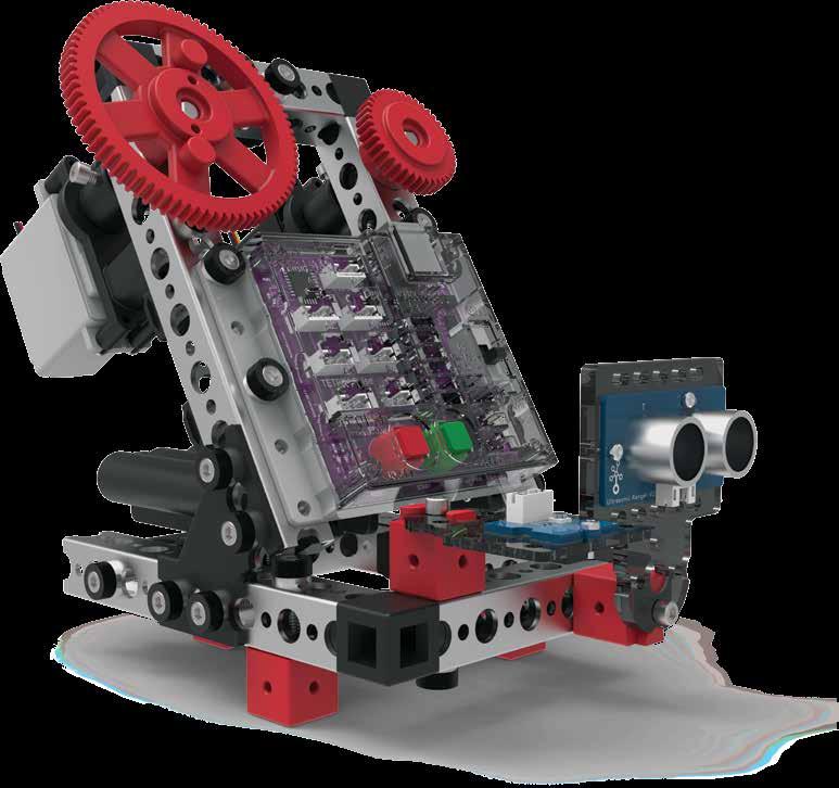
5 3 TETRIX PULSE Test Bed Activities After completing the construction of the PULSE Test Bed, it is time to have some fun. We will work through a series of activities where we program the PULSE controller to control a variety of motors and sensors plugged into the test bed. Types of Activities Each of the five activities is designed to introduce you to the TETRIX Ardublockly software and how it works with the PULSE controller and select basic hardware. Success with these five activities demonstrates how easy it is to get started building and programming robots using the TETRIX solution. Activity 1: Hello World! Complete an intro activity for beginner to blink onboard LED. Activity 2: Moving Your DC Motors Keep things simple use PULSE to control one PRIME DC Motor. Activity 3: Moving Your Servo Motors Rotate a servo motor work with positioning. Activity 4: Introduction to the Line Finder Sensor Introduce sensors and how to work with the Line Finder Sensor using PULSE. Activity 5: Introduction to the Ultrasonic Sensor Work with the Ultrasonic Sensor using PULSE.

6 4 Activity 1: Hello World! Introduction You will create a simple program, or sketch, that will blink the red LED on the PULSE controller. Think of the controller as if it s winking at you! This activity is the equivalent of a Hello World! program, which is usually the intro activity for any new programmer. The sketch you will create is a simple and basic PULSE code. Parts Needed: Pulse Test Bed USB cable Computer Open the Program Let s start by looking at the first example sketch. Open the sketch by selecting Examples > GS_Activity_1. A new sketch window will open titled GS_ Activity_1 (Figure 22). Figure 22

. Be patient!")
7 5 Background Before you can upload the sketch to the PULSE, you need to make sure the PULSE has power, is connected to the computer, and is detected by the computer. When the PULSE is connected as shown, turn on the PULSE with the on/off switch. You will know the PULSE has power by the glowing blue light. Execute the Code To upload the sketch to the PULSE, click Upload Sketch (Figure 23). To check the status of the upload, click Arduino IDE output on the bottom of the program (Figure 24). Figure 23 Figure 24 Figure 25 Watch the Upload Sketch button. A coloured line will spin around the circle while the upload is in progress (Figure 25). Be patient! As the data uploads, the yellow LEDs on the PULSE controller will flash. When the upload is finished, there will be a solid green LED light beside the red Stop/ Reset button. The green LED means the code is ready to execute. Press the green Start button to execute the code. The red LED next to the Stop/Reset button will blink off and on in one-second intervals. To stop the program, press the Stop/Reset button. Congratulations! You have successfully uploaded your first sketch to the PULSE and demonstrated the results to the world. Tip: Wait, why is the time in milliseconds? Programmers use milliseconds for more precise timing. 1,000 milliseconds equal 1 second.

8 6 Further Investigate Look at the right side of the program. You see text with different punctuation. This is called syntax, or text-based programming. Each block in the sketch is typically represented by one line of text. Lines of text within a sketch are also known as code, which is why programming is sometimes called coding. You can change some parameters in the sketch to see how they affect the behavior of the red LED. The wait block determines how long the LED will be on and off (Figure 26). This is a parameter you can change in your sketch. Experiment with changing those values to create new blinking behaviors for the LED. Try making the LED blink faster or slower. Figure 26 Tip: The time block is located under the Motors category in the software. Every program starts with a setup-loop block. Under the setup portion of the block, the pulse Begin block always comes first. Any other blocks that need to be set up only once are placed here. Blocks that will occur in a continuous loop in the program are placed in the loop portion of the block. In this example, the turning on and off of the red LED occurs over and over because it is in a loop. Only terminating the program stops the program loop (Figure 27). Extension Activity Figure 27 With the example as a reference, try creating the blinking LED in a new sketch. Instead of just blinking the red LED, try to blink the green LED too. Flashing or blinking lights can be used for signaling or long-distance communication. Challenge yourself to create a sequence of blinking LED lights like a stoplight. To start a new sketch, select File > New. Place the appropriate blocks into the sketch. When you create your own sketch, there is a built-in software tool to help ensure your code is free of errors. You can check your program by clicking Verify the Sketch (Figure 28). This will cause the code to compile but not upload. If there are errors in the code, they will be displayed in the compiler error window at the bottom of the sketch window (Figure 29). Errors will need to be corrected before code can be uploaded to the PULSE controller. Figure 28 Figure 29

9 7 If there are no errors, the compiler will complete and indicate that it is done compiling, and you can upload your code. Click the Upload the Sketch button on the sketch and see if you were able to simulate a stoplight. Real-World Link Think about the world around you. What things use blinking or flashing lights? There are many examples such as traffic lights, holiday lights, and police lights. They can serve as a warning or draw attention. Careers: traffic technician, traffic light engineer, electronic engineer STEM Connections Science Electricity LED lighting Technology Electronic design Traffic light programming Engineering Lighting types Optics Math Frequency Pattern Block-Text Correlation void setup() { pulse.pulsebegin(); void loop() { pulse.setredled(high); delay(1000); pulse.setredled(low); delay(1000); Arduino Source Code #include <PULSE.h> PULSE pulse; void setup() { pulse.pulsebegin(); } Note: Notice that On means High and Off means Low. void loop() { pulse.setredled(high); delay(1000); pulse.setredled(low); delay(1000); }
10 8 Activity 2: Moving Your DC Motors Introduction For your second activity, you will add an element of motion. You will create a sketch that will rotate a DC motor. Parts Needed: Pulse Test Bed USB cable Computer Open the Program Before you open your next example sketch, be sure to save any sketch you want to reference later. Let s start by looking at the example sketch. Open the sketch by selecting Examples > GS_Activity_2. A new sketch window will open titled GS_Activity_2 (Figure 30). Figure 30
11 9 Background The intent of this sketch is to spin a DC motor for five seconds and then stop. Then, the motor will spin in the opposite direction for five seconds. The motor will operate at half power. This behaviour will continue until the Stop/Reset button is pressed. Execute the Code Before you can upload the sketch to the PULSE, remember to check your connections. Upload the sketch. The green LED will light up, indicating that the code is ready to execute. When this has happened, press the green Start button on the PULSE controller. Observe the direction and duration of the motor rotation. Did the motor s behavior match the intended program? Press the Stop/Reset button when you are ready to stop the motor. Further Investigate The pulse Set Motor Power blocks allow you to adjust the percentage of power the motor has. It can range from 0 (no power) to 100 (full power). If you wanted half power, you would set the power to 50 (Figure 31). Figure 31 Tip: What s the difference between a DC motor and a servo motor? A DC motor has two wires and can rotate continuously. A TETRIX servo motor has three wires and can be placed into different positions but can t rotate beyond 180 degrees.
.")
. Practice changing the parameters in the sketch.")
12 10 When the program is running, you will see a red light by the motor cord when the motor is going forward, or clockwise. Within the sketch, this motor direction is represented by a positive value (Figure 32). Figure 32 When the program is running, you will see a green light by the motor cord when the motor is going backward, or counterclockwise. Within the sketch, this motor direction is represented by a negative value (Figure 33). Practice changing the parameters in the sketch. You can change the motor power, motor direction, stopping behavior, and delay between actions. Observe the effect these changes have on the motor. Extension Activity Figure 33 With the example as a reference, try creating a new sketch using your DC motor and LEDs on the controller. Remember what you learned from your first activity and come up with a creative way to include blinking LEDs with your rotating motor.

13 11 Real-World Link You can find DC motors in many places. They are in elevators, trains, machinery, power tools, cars, and fans. They are often used to power different electronics. Careers: small-engine mechanic, mechanical engineer, machinery maintenance worker STEM Connections Science Direct current Power Technology DC motor use Torque Engineering Motor wiring Ground Math Revolutions per minute (rpm) Degrees Block-Text Correlation void setup() { pulse.pulsebegin(); void loop() { pulse.setmotorpower(1,50); delay(5000); pulse.setmotorpower(1,-50); delay(5000); Note: In the parentheses, (1,50) means Motor 1 will spin clockwise at a power of 50. Arduino Source Code #include <PULSE.h> PULSE pulse; void setup() { pulse.pulsebegin(); } void loop() { pulse.setmotorpower(1,50); delay(5000); pulse.setmotorpower(1,-50); delay(5000); }

14 12 Activity 3: Moving Your Servo Motors Introduction In the third activity, you will create a sketch to rotate a servo motor. Servo motors allow movement to a set position regardless of the start position. The TETRIX servo motors have a limited range of motion from 0 to 180. For example, you can tell a servo to go to position 45 regardless of where it starts. If it starts at 0, it will move clockwise to 45. If it starts at 120, it will move counterclockwise to 45. Parts Needed: Pulse Test Bed USB cable Computer Open the Program Before you open your next example sketch, be sure to save any sketch you want to reference later. Let s start by looking at the example sketch. Open the sketch by selecting Examples > GS_Activity_3. A new sketch window will open titled GS_Activity_3 (Figure 34). Figure 34
15 13 Background In this third sketch, you will spin a servo motor back and forth between two different positions at a set speed. The motor will operate at 25% speed. This behavior will continue until the Stop/Reset button is pressed. Servo motors allow for a lot more precision in movement than DC motors do. Execute the Code Before you can upload the sketch to the PULSE, remember to check your connections. Upload the sketch. The green LED will light up, indicating that the code is ready to execute. When this has happened, press the green Start button on the PULSE controller. Observe the direction and duration of the servo motor rotation. Did the motor s behavior match the intended program? Press the Stop/Reset button when you are ready to stop the motor. Further Investigate In this sketch, you will use two new PULSE blocks: pulse Set Servo Speed and pulse Set Servo Position. Both blocks have two parameters, but they are different. The two parameters of the pulse Set Servo Speed block are servo channel and servo speed. In the example, Servo 1 will spin at 25% power while it rotates to the position commanded by the pulse Set Servo Position block. This block is in the setup portion of the setup-loop block because it needs to be listed once at the beginning of the program (Figure 35). Figure 35 Tip: What s the difference between a DC motor and a servo motor? A DC motor has two wires and can rotate continuously. A TETRIX servo motor has three wires and can be placed into different positions but can t rotate beyond 180 degrees.
.")
16 14 The two parameters of the pulse Set Servo Position block are servo channel and target position. In the example, pulse Set Servo Position means Servo 1 will rotate to the target position of 180. It then changes position to 0 but continues at the same speed. This servo will continue to change position because the program will continue to execute the loop until the program is ended (Figure 36). Figure 36 In the sketch, both blocks work together to tell the servo motor not only the target position but also the speed to use while moving to the target position. You can alter the position and speed of the servo by changing the values of both functions. Practice changing the parameters in the sketch. Observe the effect these changes have on the servo motor. Extension Activity With the example as a reference, try creating a new sketch to move your servo motor. You could also incorporate the use of your DC motor and LEDs on the controller. Remember what you learned from your previous activities and think of creative ways to combine the functions you have learned.

17 15 Real-World Link You can find servo motors in R/C model cars for steering and R/C model airplanes for controlling flaps and rudders. Servos are used where precise movement is needed such as in the operation of robotic arms, grippers, and rotating camera mounts. Careers: fabricator, industrial engineer, machinist STEM Connections Science Current Fleming s rules Technology Motor assembly Feedback system Engineering Energy conversion Motor gearing Math Accuracy Precision Block-Text Correlation void setup() { pulse.pulsebegin(); pulse.setservospeed(1,25); void loop() { pulse.setservoposition(1,180); delay(3000); pulse.setservoposition(1,0); delay(3000); Note: The servo motor changes position from 0 degrees to 180 degrees. Arduino Source Code #include <PULSE.h> PULSE pulse; void setup() { pulse.pulsebegin(); pulse.setservospeed(1,25); } void loop() { pulse.setservoposition(1,180); delay(3000); pulse.setservoposition(1,0); delay(3000); }

18 16 Activity 4: Introduction to the Line Finder Sensor Introduction For the fourth activity, you will use a line-finding sensor. In this example, you will connect a Line Finder Sensor to digital sensor port D2. You will create a sketch to read digital input from the Line Finder Sensor. Sensors enable us to gather information from the world around us. The type of information depends on the type of sensor. The Line Finder Sensor uses reflected infrared light to distinguish between light and dark surfaces. Parts Needed: Pulse Test Bed USB cable Computer Contrasting light and dark surface Open the Program Before you open your next example sketch, be sure to save any sketch you want to reference later. Let s start by looking at the example sketch. Open the sketch by selecting Examples > GS_Activity_4. A new sketch window will open titled GS_Activity_4 (Figure 37). Figure 37
.")
19 17 Background For the fourth sketch, you will take a closer look at programming a sensor and using a logic block. You will use the Line Finder Sensor to determine whether a surface is light or dark. The if-do logic block does exactly what its name suggests. Everything contained within the loop will repeat consecutively until the sketch is ended with a command or the Stop/Reset button (Figure 38). Depending on the surface, a red or yellow LED will light up on the PULSE controller. Execute the Code Figure 38 Before you can upload the sketch to the PULSE, remember to check your connections. Upload the sketch. The green LED will light up, indicating the code is ready to execute. When this has happened, press the green Start button on the PULSE controller. Hold the sensor over a contrasting surface. As the sensor moves from light to dark, observe the red LED on the PULSE. When the sensor is over a nonreflective or dark surface, the yellow LED will be on. When the sensor is over a white or reflective surface, the red LED will be on. Press the Stop/Reset button when you are ready to stop the sensor.
. The comparison statement = (equal to) defines a type of test.")


20 18 Further Investigate This sketch introduces a program structure, new blocks, and a comparison statement. The program structure is an if statement, the reading of the sensor, and the comparison statement is = (equal to). The comparison statement = (equal to) defines a type of test. In this sketch, the input of the Line Finder Sensor will turn different LEDs on or off. The basic if statement enables us to test for a certain condition. If this condition is met, then the program can perform an action. If the variable in the if section of the loop block is true, then the blocks within the do section are run. In this instance, the output of the Line Finder Sensor must equal 1, or HIGH, for the do section to run (Figure 39). Figure 39 If the if portion of the loop block isn t true, then the else if portion enables you to test for a different condition. If this condition is met, then the blocks within the do section under the else if section will run. In the else if portion, the output of the Line Finder Sensor must equal 0, or LOW (Figure 40). Figure 40 The Line Finder Sensor can return a value of 1 (HIGH) or 0 (LOW). A value of 1 is returned when the Line Finder Sensor detects a dark line or a nonreflective surface; a value of 0 is returned when the Line Finder Sensor detects a white or reflective surface. If the Line Finder Sensor detects a line or a nonreflective surface, then it turns the red LED on. Think of it as an object placed in its path. The red LED on the Line Finder Sensor also lights up. In the program, this occurs when the line variable is set to LOW. If the Line Finder Sensor detects a white or reflective surface, it turns the yellow LED on. In the program, this occurs when the line variable is set to HIGH (Figure 41). Figure 41
21 19 Experiment with the Line Finder Sensor on different surfaces and different heights to see how the sensor reacts. Extension Activity With the example as a reference, try creating a new sketch to use your Line Finder Sensor. Remember what you learned from your previous activities and think of additional creative actions to perform based on the condition of the Line Finder Sensor. Real-World Link There are many uses for a robot that can follow a line. Automated robots are being developed to follow lines to deliver materials within hospitals. In the future, they could also move materials around warehouses or transport goods. Careers: materials engineer, electromechanical technician, software developer STEM Connections Science Light Electromagnetic spectrum Technology Guidance system Automation Engineering Microcontroller Embedded system Math Angles Lines Block-Text Correlation Arduino Source Code #include <PULSE.h> PULSE pulse; void setup() { pulse.pulsebegin(); } void loop() { if (pulse.readlinesensor(2) == 1) { pulse.setredled(low); pulse.setyellowled(high); } else if (pulse.readlinesensor(2) == 0) { pulse.setredled(high); pulse.setyellowled(low); } } void setup() { pulse.pulsebegin(); void loop() { if (pulse.readlinesensor(2) == 1) { pulse.setredled(low); pulse.setyellowled(high); } else if (pulse.readlinesensor(2) == 0) { pulse.setredled(high); pulse.setyellowled(low); Note: All the actions completed in the if () or if/else () loops are contained within braces.
22 20 Activity 5: Introduction to the Ultrasonic Sensor Introduction For the final getting started activity, you will finish up your exploration of sensors by creating a sketch using the Ultrasonic Sensor. In this activity, you will connect an Ultrasonic Sensor to digital sensor port D3 and display the distance to an object you place in front of it using the serial monitor window. Like all sensors, the Ultrasonic Sensor enables us to gather information. The Ultrasonic Sensor gathers information to communicate distance. The sensor works by sending a sonic pulse burst and then waiting on its return as it is reflected off an object in range. The reflected sonic pulse time period is measured to determine the distance to the object. The sensor has a measuring range of approximately centimeters. Parts Needed: Pulse Test Bed USB cable Computer Open the Program Before you open your next example sketch, be sure to save any sketch you want to reference later. Let s start by looking at the example sketch. Open the sketch by selecting Examples > GS_Activity_5. A new sketch window will open titled GS_Activity_5 (Figure 42). Figure 42
23 21 Background For your fifth sketch, you will use the Ultrasonic Sensor, which sends out pulses that measure the distance from the sensor to the object. You will use the same logic block from the previous activity. Instead of measuring light, this sensor will measure distance. Depending on the distance of the object from the sensor, a red or yellow LED will light up on the PULSE controller. Execute the Code Before you can upload the sketch to the PULSE, remember to check your connections. Upload the sketch. With the sensor lying flat on the desk pointed up, press the green Start button to execute the code. Hold your hand above the sensor. Move it up and down. Watch what happens to the LEDs on the PULSE controller. Press the Stop/Reset button when you are ready to stop the sensor.

24 22 Further Investigate In this sketch, the input of the Ultrasonic Sensor will turn different LEDs on or off. If the variable in the if section of the loop block is true, then the blocks within the do section of the loop block are run. In this instance, if there isn t an object closer than 10 cm to the Ultrasonic Sensor, the yellow LED on the PULSE controller will be lit (Figure 43). If the if portion of the loop block isn t true, then the else if portion enables you to test for a different condition. If this condition is met, then the blocks within the do section under the else if section will run. In this instance, if there is an object closer than 10 cm to the Ultrasonic Sensor, the red LED on the PULSE controller will be lit. Experiment with the Ultrasonic Sensor with different objects and different heights to see how the sensor reacts. Extension Activity Figure 43 With the example as a reference, try creating a new sketch to use your Ultrasonic Sensor. Remember what you learned from your previous activities and experiment with different objects in front of the Ultrasonic Sensor to see if they are detectable. You can also program the motors to stop when an object reaches a certain distance from the Ultrasonic Sensor. Try changing the distance units on the pulse Ultrasonic Sensor block from centimeters to inches. Understanding how to use the Ultrasonic Sensor will give your robot vision so that it can steer around objects and obstacles (Figure 44). Figure 44 Tip: To solve this extension activity, you can find a sample sketch in the appendix titled GS_Activity_5_Extension_Example.
25 23 Real-World Link Modern vehicles are smart. They have backup cameras and assisted parallel parking and will even beep at you if an object is too close to the car. This is how an ultrasonic sensor works! Careers: car designer, sound engineering technician, sonar technician STEM Connections Science Sound waves Reflection of sound waves Technology Frequency Sound digitization Engineering Sonic measurements Sonar Math Distance Comparison symbols Block-Text Correlation void setup() { pulse.pulsebegin(); void loop() { if (pulse.readsonicsensorcm(3) > 10) { pulse.setredled(low); pulse.setyellowled(high); } else if (pulse.readsonicsensorcm(3) < 10) { pulse.setredled(high); pulse.setyellowled(low); Arduino Source Code #include <PULSE.h> PULSE pulse; Note: This program uses the math values of greater than (>) and less than (<). A specific LED will be lit depending on whether the output value is greater than or less than 10. void setup() { pulse.pulsebegin(); } void loop() { if (pulse.readsonicsensorcm(3) > 10) { pulse.setredled(low); pulse.setyellowled(high); } else if (pulse.readsonicsensorcm(3) < 10) { pulse.setredled(high); pulse.setyellowled(low); } }
26 24
27 1. Which of the following best describes your role? Classroom teacher Building administrator District administrator College professor Informal education (e.g., library, museum) Content specialist (e.g., reading teacher, gifted and talented coordinator) Other 2. Which of the following best describes your school? Public Private Charter University Other 3. Which grade level(s) of students do you work with? K-2 Postsecondary 3-5 After school 6-8 Summer camps 9-12 I don t teach. Conference Presentation Evaluation Topic: 8. Did the session cover the content that you expected it to? If not, what was different? 9. How likely are you to recommend the session or product to a friend or colleague? (10 is extremely likely, and 0 is not at all likely.) This session? The product? Do you have any input for the presenter or future presentations? 4. Which of these subject areas do you teach? Science Technology Engineering Math Robotics competitions Robotics in the classroom 11. Have you ever used the product that was demonstrated in the workshop? Yes No 12. What ideas do you have about how you might use this product in your classroom? 5. How many years have you been teaching? 1st year years 2-5 years 21+ years 6-10 years I don t teach. 6. Please provide your address: 13. What is your favorite takeaway from this workshop? 7. How strongly do you agree with the following statements? (1 = strongly disagree, 3 = neutral, 5 = strongly agree) This session was selected for immediate classroom use This session was selected to improve my personal pedagogical knowledge/skill This session met my needs The information in this session was clear and well organized Safe practices were employed during the session Please share any other comments you might have regarding the workshop and your overall experience. Use the back of this sheet if needed. Add your contact information to the back of this sheet to be entered in the drawing.


28 Visit TETRIXrobotics.com for more information about TETRIX PRIME and TETRIX MAX.
TETRIX PRIZM Workshop Guide
 TETRIX PRIZM Workshop Guide 43527 1 Who Are We and Why Are We Here? Who is Pitsco? Pitsco s unwavering focus on innovative educational solutions and unparalleled customer service began when the company
Arduino Control of Tetrix Prizm Robotics. Motors and Servos Introduction to Robotics and Engineering Marist School
 Arduino Control of Tetrix Prizm Robotics Motors and Servos Introduction to Robotics and Engineering Marist School Motor or Servo? Motor Faster revolution but less Power Tetrix 12 Volt DC motors have a
Objectives: Learn what an Arduino is and what it can do Learn what an LED is and how to use it Be able to wire and program an LED to blink
 Objectives: Learn what an Arduino is and what it can do Learn what an LED is and how to use it Be able to wire and program an LED to blink By the end of this session: You will know how to use an Arduino
A servo is an electric motor that takes in a pulse width modulated signal that controls direction and speed. A servo has three leads:
 Project 4: Arduino Servos Part 1 Description: A servo is an electric motor that takes in a pulse width modulated signal that controls direction and speed. A servo has three leads: a. Red: Current b. Black:
A Day in the Life CTE Enrichment Grades 3-5 mblock Programs Using the Sensors
 Activity 1 - Reading Sensors A Day in the Life CTE Enrichment Grades 3-5 mblock Programs Using the Sensors Computer Science Unit This tutorial teaches how to read values from sensors in the mblock IDE.
Programming 2 Servos. Learn to connect and write code to control two servos.
 Programming 2 Servos Learn to connect and write code to control two servos. Many students who visit the lab and learn how to use a Servo want to use 2 Servos in their project rather than just 1. This lesson
J. La Favre Using Arduino with Raspberry Pi February 7, 2018
 As you have already discovered, the Raspberry Pi is a very capable digital device. Nevertheless, it does have some weaknesses. For example, it does not produce a clean pulse width modulation output (unless
MAKER: Development of Smart Mobile Robot System to Help Middle School Students Learn about Robot Perception
 Paper ID #14537 MAKER: Development of Smart Mobile Robot System to Help Middle School Students Learn about Robot Perception Dr. Sheng-Jen Tony Hsieh, Texas A&M University Dr. Sheng-Jen ( Tony ) Hsieh is
Where C= circumference, π = 3.14, and D = diameter EV3 Distance. Developed by Joanna M. Skluzacek Wisconsin 4-H 2016 Page 1
 Instructor Guide Title: Distance the robot will travel based on wheel size Introduction Calculating the distance the robot will travel for each of the duration variables (rotations, degrees, seconds) can
CURIE Academy, Summer 2014 Lab 2: Computer Engineering Software Perspective Sign-Off Sheet
 Lab : Computer Engineering Software Perspective Sign-Off Sheet NAME: NAME: DATE: Sign-Off Milestone TA Initials Part 1.A Part 1.B Part.A Part.B Part.C Part 3.A Part 3.B Part 3.C Test Simple Addition Program
Chapter 14. using data wires
 Chapter 14. using data wires In this fifth part of the book, you ll learn how to use data wires (this chapter), Data Operations blocks (Chapter 15), and variables (Chapter 16) to create more advanced programs
Medb ot. Medbot. Learn about robot behaviors as you transport medicine in a hospital with Medbot!
 Medb ot Medbot Learn about robot behaviors as you transport medicine in a hospital with Medbot! Seek Discover new hands-on builds and programming opportunities to further your understanding of a subject
Lesson 3: Arduino. Goals
 Introduction: This project introduces you to the wonderful world of Arduino and how to program physical devices. In this lesson you will learn how to write code and make an LED flash. Goals 1 - Get to
Introduction to the VEX Robotics Platform and ROBOTC Software
 Introduction to the VEX Robotics Platform and ROBOTC Software Computer Integrated Manufacturing 2013 Project Lead The Way, Inc. VEX Robotics Platform: Testbed for Learning Programming VEX Structure Subsystem
Welcome to Arduino Day 2016
 Welcome to Arduino Day 2016 An Intro to Arduino From Zero to Hero in an Hour! Paul Court (aka @Courty) Welcome to the SLMS Arduino Day 2016 Arduino / Genuino?! What?? Part 1 Intro Quick Look at the Uno
EE-110 Introduction to Engineering & Laboratory Experience Saeid Rahimi, Ph.D. Labs Introduction to Arduino
 EE-110 Introduction to Engineering & Laboratory Experience Saeid Rahimi, Ph.D. Labs 10-11 Introduction to Arduino In this lab we will introduce the idea of using a microcontroller as a tool for controlling
Coding with Arduino to operate the prosthetic arm
 Setup Board Install FTDI Drivers This is so that your RedBoard will be able to communicate with your computer. If you have Windows 8 or above you might already have the drivers. 1. Download the FTDI driver
Mechatronics Engineering and Automation Faculty of Engineering, Ain Shams University MCT-151, Spring 2015 Lab-4: Electric Actuators
 Mechatronics Engineering and Automation Faculty of Engineering, Ain Shams University MCT-151, Spring 2015 Lab-4: Electric Actuators Ahmed Okasha, Assistant Lecturer okasha1st@gmail.com Objective Have a
StenBOT Robot Kit. Stensat Group LLC, Copyright 2018
 StenBOT Robot Kit 1 Stensat Group LLC, Copyright 2018 Legal Stuff Stensat Group LLC assumes no responsibility and/or liability for the use of the kit and documentation. There is a 90 day warranty for the
Arduino STEAM Academy Arduino STEM Academy Art without Engineering is dreaming. Engineering without Art is calculating. - Steven K.
 Arduino STEAM Academy Arduino STEM Academy Art without Engineering is dreaming. Engineering without Art is calculating. - Steven K. Roberts Page 1 See Appendix A, for Licensing Attribution information
VEX Robotics Platform and ROBOTC Software. Introduction
 VEX Robotics Platform and ROBOTC Software Introduction VEX Robotics Platform: Testbed for Learning Programming VEX Structure Subsystem VEX Structure Subsystem forms the base of every robot Contains square
Inspiring Creative Fun Ysbrydoledig Creadigol Hwyl. S4A - Scratch for Arduino Workbook
 Inspiring Creative Fun Ysbrydoledig Creadigol Hwyl S4A - Scratch for Arduino Workbook 1) Robotics Draw a robot. Consider the following and annotate: What will it look like? What will it do? How will you
I.1 Smart Machines. Unit Overview:
 I Smart Machines I.1 Smart Machines Unit Overview: This unit introduces students to Sensors and Programming with VEX IQ. VEX IQ Sensors allow for autonomous and hybrid control of VEX IQ robots and other
FABO ACADEMY X ELECTRONIC DESIGN
 ELECTRONIC DESIGN MAKE A DEVICE WITH INPUT & OUTPUT The Shanghaino can be programmed to use many input and output devices (a motor, a light sensor, etc) uploading an instruction code (a program) to it
In this activity, you will program the BASIC Stamp to control the rotation of each of the Parallax pre-modified servos on the Boe-Bot.
 Week 3 - How servos work Testing the Servos Individually In this activity, you will program the BASIC Stamp to control the rotation of each of the Parallax pre-modified servos on the Boe-Bot. How Servos
Programming a Servo. Servo. Red Wire. Black Wire. White Wire
 Programming a Servo Learn to connect wires and write code to program a Servo motor. If you have gone through the LED Circuit and LED Blink exercises, you are ready to move on to programming a Servo. A
LESSONS Lesson 1. Microcontrollers and SBCs. The Big Idea: Lesson 1: Microcontrollers and SBCs. Background: What, precisely, is computer science?
 LESSONS Lesson Lesson : Microcontrollers and SBCs Microcontrollers and SBCs The Big Idea: This book is about computer science. It is not about the Arduino, the C programming language, electronic components,
Programming Design ROBOTC Software
 Programming Design ROBOTC Software Computer Integrated Manufacturing 2013 Project Lead The Way, Inc. Behavior-Based Programming A behavior is anything your robot does Example: Turn on a single motor or
Exercise 2. Point-to-Point Programs EXERCISE OBJECTIVE
 Exercise 2 Point-to-Point Programs EXERCISE OBJECTIVE In this exercise, you will learn various important terms used in the robotics field. You will also be introduced to position and control points, and
Your EdVenture into Robotics 10 Lesson plans
 Your EdVenture into Robotics 10 Lesson plans Activity sheets and Worksheets Find Edison Robot @ Search: Edison Robot Call 800.962.4463 or email custserv@ Lesson 1 Worksheet 1.1 Meet Edison Edison is a
Hobby Servo Tutorial. Introduction. Sparkfun: https://learn.sparkfun.com/tutorials/hobby-servo-tutorial
 Hobby Servo Tutorial Sparkfun: https://learn.sparkfun.com/tutorials/hobby-servo-tutorial Introduction Servo motors are an easy way to add motion to your electronics projects. Originally used in remotecontrolled
OZOBOT BASIC TRAINING LESSON 1 WHAT IS OZOBOT?
 OZOBOT BASIC TRAINING LESSON 1 WHAT IS OZOBOT? What students will learn What kind of a robot is Ozobot? How does Ozobot sense its environment and move in it? How can you give commands to Ozobot? Topics
Arduino Lesson 1. Blink. Created by Simon Monk
 Arduino Lesson 1. Blink Created by Simon Monk Guide Contents Guide Contents Overview Parts Part Qty The 'L' LED Loading the 'Blink' Example Saving a Copy of 'Blink' Uploading Blink to the Board How 'Blink'
Robotics Workshop. for Parents and Teachers. September 27, 2014 Wichita State University College of Engineering. Karen Reynolds
 Robotics Workshop for Parents and Teachers September 27, 2014 Wichita State University College of Engineering Steve Smith Christa McAuliffe Academy ssmith3@usd259.net Karen Reynolds Wichita State University
Lab book. Exploring Robotics (CORC3303)
") Lab book Exploring Robotics (CORC3303) Dept of Computer and Information Science Brooklyn College of the City University of New York updated: Fall 2011 / Professor Elizabeth Sklar UNIT A Lab, part 1 : Robot
Lab book Exploring Robotics (CORC3303) Dept of Computer and Information Science Brooklyn College of the City University of New York updated: Fall 2011 / Professor Elizabeth Sklar UNIT A Lab, part 1 : Robot
Name & SID 1 : Name & SID 2:
 EE40 Final Project-1 Smart Car Name & SID 1 : Name & SID 2: Introduction The final project is to create an intelligent vehicle, better known as a robot. You will be provided with a chassis(motorized base),
Setup Download the Arduino library (link) for Processing and the Lab 12 sketches (link).
 for Processing and the Lab 12 sketches (link).") Lab 12 Connecting Processing and Arduino Overview In the previous lab we have examined how to connect various sensors to the Arduino using Scratch. While Scratch enables us to make simple Arduino programs,
Lab 12 Connecting Processing and Arduino Overview In the previous lab we have examined how to connect various sensors to the Arduino using Scratch. While Scratch enables us to make simple Arduino programs,
Computational Crafting with Arduino. Christopher Michaud Marist School ECEP Programs, Georgia Tech
 Computational Crafting with Arduino Christopher Michaud Marist School ECEP Programs, Georgia Tech Introduction What do you want to learn and do today? Goals with Arduino / Computational Crafting Purpose
1 Day Robot Building (MC40A + Aluminum Base) for Edubot 2.0
 for Edubot 2.0") 1 Day Robot Building (MC40A + Aluminum Base) for Edubot 2.0 Have you ever thought of making a mobile robot in 1 day? Now you have the chance with MC40A Mini Mobile Robot Controller + some accessories.
1 Day Robot Building (MC40A + Aluminum Base) for Edubot 2.0 Have you ever thought of making a mobile robot in 1 day? Now you have the chance with MC40A Mini Mobile Robot Controller + some accessories.
Lesson 13. The Big Idea: Lesson 13: Infrared Transmitters
 Lesson Lesson : Infrared Transmitters The Big Idea: In Lesson 12 the ability to detect infrared radiation modulated at 38,000 Hertz was added to the Arduino. This lesson brings the ability to generate
Robotics Engineering DoDEA Career Technology Education Robot Programming
 Robotics Engineering DoDEA Career Technology Education Robot Programming Area Competency G. Robot Programming 1. Introduction to Robot Programming ( / / ) ( / / ) Before you get started, print out this
Students will design, program, and build a robot vehicle to traverse a maze in 30 seconds without touching any sidewalls or going out of bounds.
 Overview Challenge Students will design, program, and build a robot vehicle to traverse a maze in 30 seconds without touching any sidewalls or going out of bounds. Materials Needed One of these sets: TETRIX
The light sensor, rotation sensor, and motors may all be monitored using the view function on the RCX.
 Review the following material on sensors. Discuss how you might use each of these sensors. When you have completed reading through this material, build a robot of your choosing that has 2 motors (connected
Parts List. Robotic Arm segments ¼ inch screws Cable XBEE module or Wifi module
 Robotic Arm 1 Legal Stuff Stensat Group LLC assumes no responsibility and/or liability for the use of the kit and documentation. There is a 90 day warranty for the Sten-Bot kit against component defects.
Lab 2: Blinkie Lab. Objectives. Materials. Theory
 Lab 2: Blinkie Lab Objectives This lab introduces the Arduino Uno as students will need to use the Arduino to control their final robot. Students will build a basic circuit on their prototyping board and
Getting Started with the micro:bit
 Page 1 of 10 Getting Started with the micro:bit Introduction So you bought this thing called a micro:bit what is it? micro:bit Board DEV-14208 The BBC micro:bit is a pocket-sized computer that lets you
AC : THE UBIQUITOUS MICROCONTROLLER IN MECHANICAL ENGINEERING: MEASUREMENT SYSTEMS
 AC 8-1513: THE UBIQUITOUS MICROCONTROLLER IN MECHANICAL ENGINEERING: MEASUREMENT SYSTEMS Michael Holden, California Maritime Academy Michael Holden teaches in the department of Mechanical Engineering at
Robots in Town Autonomous Challenge. Overview. Challenge. Activity. Difficulty. Materials Needed. Class Time. Grade Level. Objectives.
 Overview Challenge Students will design, program, and build a robot that drives around in town while avoiding collisions and staying on the roads. The robot should turn around when it reaches the outside
STEM in Practice AISWA SAMPLE. with KodeKLIX. Def ine Plan Model Test Ref lect Improve NAME: STUDENT WORKBOOK
 STUDENT WORKBOOK STEM in Practice with KodeKLIX NAME: Def ine Plan Model Test Ref lect Improve www.ais.wa.edu.au Peter Crosbie kodeklix.com Jan Clarke STUDENT WORKBOOK TABLE OF CONTENTS W W SECTION 1:
Program.
 Program Introduction S TE AM www.kiditech.org About Kiditech In Kiditech's mighty world, we coach, play and celebrate an innovative technology program: K-12 STEAM. We gather at Kiditech to learn and have
Nebraska 4-H Robotics and GPS/GIS and SPIRIT Robotics Projects
 Name: Club or School: Robots Knowledge Survey (Pre) Multiple Choice: For each of the following questions, circle the letter of the answer that best answers the question. 1. A robot must be in order to
Erik Von Burg Mesa Public Schools Gifted and Talented Program Johnson Elementary School
 Erik Von Burg Mesa Public Schools Gifted and Talented Program Johnson Elementary School elvonbur@mpsaz.org Water Sabers (2008)* High Heelers (2009)* Helmeteers (2009)* Cyber Sleuths (2009)* LEGO All Stars
1. Controlling the DC Motors
 E11: Autonomous Vehicles Lab 5: Motors and Sensors By this point, you should have an assembled robot and Mudduino to power it. Let s get things moving! In this lab, you will write code to test your motors
General Description. The TETRIX MAX Servo Motor Expansion Controller features the following:
 General Description The TETRIX MAX Servo Motor Expansion Controller is a servo motor expansion peripheral designed to allow the addition of multiple servo motors to the PRIZM Robotics Controller. The device
100UF CAPACITOR POTENTIOMETER SERVO MOTOR MOTOR ARM. MALE HEADER PIN (3 pins) INGREDIENTS
 INGREDIENTS") 05 POTENTIOMETER SERVO MOTOR MOTOR ARM 100UF CAPACITOR MALE HEADER PIN (3 pins) INGREDIENTS 63 MOOD CUE USE A SERVO MOTOR TO MAKE A MECHANICAL GAUGE TO POINT OUT WHAT SORT OF MOOD YOU RE IN THAT DAY Discover:
05 POTENTIOMETER SERVO MOTOR MOTOR ARM 100UF CAPACITOR MALE HEADER PIN (3 pins) INGREDIENTS 63 MOOD CUE USE A SERVO MOTOR TO MAKE A MECHANICAL GAUGE TO POINT OUT WHAT SORT OF MOOD YOU RE IN THAT DAY Discover:
For this exercise, you will need a partner, an Arduino kit (in the plastic tub), and a laptop with the Arduino programming environment.
, and a laptop with the Arduino programming environment.") Physics 222 Name: Exercise 6: Mr. Blinky This exercise is designed to help you wire a simple circuit based on the Arduino microprocessor, which is a particular brand of microprocessor that also includes
Physics 222 Name: Exercise 6: Mr. Blinky This exercise is designed to help you wire a simple circuit based on the Arduino microprocessor, which is a particular brand of microprocessor that also includes
Workshops Elisava Introduction to programming and electronics (Scratch & Arduino)
") Workshops Elisava 2011 Introduction to programming and electronics (Scratch & Arduino) What is programming? Make an algorithm to do something in a specific language programming. Algorithm: a procedure
Workshops Elisava 2011 Introduction to programming and electronics (Scratch & Arduino) What is programming? Make an algorithm to do something in a specific language programming. Algorithm: a procedure
Worksheet Answer Key: Tree Measurer Projects > Tree Measurer
 Worksheet Answer Key: Tree Measurer Projects > Tree Measurer Maroon = exact answers Magenta = sample answers Construct: Test Questions: Caliper Reading Reading #1 Reading #2 1492 1236 1. Subtract to find
Automobile Prototype Servo Control
 IJIRST International Journal for Innovative Research in Science & Technology Volume 2 Issue 10 March 2016 ISSN (online): 2349-6010 Automobile Prototype Servo Control Mr. Linford William Fernandes Don Bosco
understanding sensors
 The LEGO MINDSTORMS EV3 set includes three types of sensors: Touch, Color, and Infrared. You can use these sensors to make your robot respond to its environment. For example, you can program your robot
UNIT1. Keywords page 13-14
 UNIT1 Keywords page 13-14 What is a Robot? A robot is a machine that can do the work of a human. Robots can be automatic, or they can be computer-controlled. Robots are a part of everyday life. Most robots
Advanced Mechatronics 1 st Mini Project. Remote Control Car. Jose Antonio De Gracia Gómez, Amartya Barua March, 25 th 2014
 Advanced Mechatronics 1 st Mini Project Remote Control Car Jose Antonio De Gracia Gómez, Amartya Barua March, 25 th 2014 Remote Control Car Manual Control with the remote and direction buttons Automatic
CONSTRUCTION GUIDE Robotic Arm. Robobox. Level II
 CONSTRUCTION GUIDE Robotic Arm Robobox Level II Robotic Arm This month s robot is a robotic arm with two degrees of freedom that will teach you how to use motors. You will then be able to move the arm
Total Hours Registration through Website or for further details please visit (Refer Upcoming Events Section)
") Total Hours 110-150 Registration Q R Code Registration through Website or for further details please visit http://www.rknec.edu/ (Refer Upcoming Events Section) Module 1: Basics of Microprocessor & Microcontroller
Total Hours 110-150 Registration Q R Code Registration through Website or for further details please visit http://www.rknec.edu/ (Refer Upcoming Events Section) Module 1: Basics of Microprocessor & Microcontroller
Ev3 Robotics Programming 101
 Ev3 Robotics Programming 101 1. EV3 main components and use 2. Programming environment overview 3. Connecting your Robot wirelessly via bluetooth 4. Starting and understanding the EV3 programming environment
UNIT 4 VOCABULARY SKILLS WORK FUNCTIONS QUIZ. A detailed explanation about Arduino. What is Arduino? Listening
 UNIT 4 VOCABULARY SKILLS WORK FUNCTIONS QUIZ 4.1 Lead-in activity Find the missing letters Reading A detailed explanation about Arduino. What is Arduino? Listening To acquire a basic knowledge about Arduino
Morse Code Autonomous Challenge. Overview. Challenge. Activity. Difficulty. Materials Needed. Class Time. Grade Level. Learning Focus.
 Overview Challenge Students will design, program, and build a robot that communicates with Morse code. The robot must use its communication system to tell the operator when the robot completes each task
the Board of Education
 the Board of Education Voltage regulator electrical power (V dd, V in, V ss ) breadboard (for building circuits) power jack digital input / output pins 0 to 15 reset button Three-position switch 0 = OFF
We re excited to launch the newest in our line of circuits: Very Useful Circuits
 Very Useful Circuits Lectrical engineering for all ages Since launching Lectrify in 2015, we ve enabled thousands of children in classrooms and camps to build their first circuits using LEGO and common
Devastator Tank Mobile Platform with Edison SKU:ROB0125
 Devastator Tank Mobile Platform with Edison SKU:ROB0125 From Robot Wiki Contents 1 Introduction 2 Tutorial 2.1 Chapter 2: Run! Devastator! 2.2 Chapter 3: Expansion Modules 2.3 Chapter 4: Build The Devastator
RG Kit Guidebook ARGINEERING
 RG Kit Guidebook ARGINEERING RG Kit Guidebook ARGINEERING ARGINEERING The desire to interact, to connect exists in us all. As interactive beings, we interact not only with each other, but with the world
Lesson4 Obstacle avoidance car
 Lesson4 Obstacle avoidance car 1 Points of this section The joy of learning, is not just know how to control your car, but also know how to protect your car. So, make you car far away from collision. Learning
Programming Design. ROBOTC Software
 Programming Design ROBOTC Software Behavior-Based Programming A behavior is anything your robot does Turning on a single motor or servo Three main types of behaviors 1. Complex behaviors Robot performs
Built-in soft-start feature. Up-Slope and Down-Slope. Power-Up safe start feature. Motor will only start if pulse of 1.5ms is detected.
 Thank You for purchasing our TRI-Mode programmable DC Motor Controller. Our DC Motor Controller is the most flexible controller you will find. It is user-programmable and covers most applications. This
EQ-ROBO Programming : bomb Remover Robot
 EQ-ROBO Programming : bomb Remover Robot Program begin Input port setting Output port setting LOOP starting point (Repeat the command) Condition 1 Key of remote controller : LEFT UP Robot go forwards after
EDUCATORS INFORMATION GUIDE
 EDUCATORS INFORMATION GUIDE TABLE OF CONTENTS Arduino Education: Inspiring, Teaching and Empowering What is Arduino? 5 The Education Team And Its Mission 5 Current Use Cases in Education 5 Features and
Some prior experience with building programs in Scratch is assumed. You can find some introductory materials here:
 Robotics 1b Building an mbot Program Some prior experience with building programs in Scratch is assumed. You can find some introductory materials here: http://www.mblock.cc/edu/ The mbot Blocks The mbot
ROBOTICS & IOT. Workshop Module
 ROBOTICS & IOT Workshop Module CURRICULUM STRUCTURE DURATION : 2 day (16 hours) Session 1 Let's Learn Embedded System & Robotics Description Under this topic, we will discuss basics and give brief idea
ROBOTICS & IOT. Workshop Module
 ROBOTICS & IOT Workshop Module CURRICULUM STRUCTURE DURATION : 2 day (16 hours) Session 1 Let's Learn Embedded System & Robotics Description Under this topic, we will discuss basics and give brief idea
PLAN DE FORMACIÓN EN LENGUAS EXTRANJERAS IN-57 Technology for ESO: Contents and Strategies
 Lesson Plan: Traffic light with Arduino using code, S4A and Ardublock Course 3rd ESO Technology, Programming and Robotic David Lobo Martínez David Lobo Martínez 1 1. TOPIC Arduino is an open source hardware
Studuino Icon Programming Environment Guide
 Studuino Icon Programming Environment Guide Ver 0.9.6 4/17/2014 This manual introduces the Studuino Software environment. As the Studuino programming environment develops, these instructions may be edited
Revision for Grade 7 in Unit #1&3
 Your Name:.... Grade 7 / SEION 1 Matching :Match the terms with its explanations. Write the matching letter in the correct box. he first one has been done for you. (1 mark each) erm Explanation 1. electrical
DXXX Series Servo Programming...9 Introduction...9 Connections HSB-9XXX Series Servo Programming...19 Introduction...19 Connections...
 DPC-11 Operation Manual Table of Contents Section 1 Introduction...2 Section 2 Installation...4 Software Installation...4 Driver Installastion...7 Section 3 Operation...9 D Series Servo Programming...9
Demon Pumpkin APPROXIMATE TIME (EXCLUDING PREPARATION WORK): 1 HOUR PREREQUISITES: PART LIST:
: 1 HOUR PREREQUISITES: PART LIST:") Demon Pumpkin This is a lab guide for creating your own simple animatronic pumpkin. This project encourages students and makers to innovate upon the base design to add their own personal touches. APPROXIMATE
Demon Pumpkin This is a lab guide for creating your own simple animatronic pumpkin. This project encourages students and makers to innovate upon the base design to add their own personal touches. APPROXIMATE
Attribution Thank you to Arduino and SparkFun for open source access to reference materials.
 Attribution Thank you to Arduino and SparkFun for open source access to reference materials. Contents Parts Reference... 1 Installing Arduino... 7 Unit 1: LEDs, Resistors, & Buttons... 7 1.1 Blink (Hello
An Introduction to Programming using the NXT Robot:
 An Introduction to Programming using the NXT Robot: exploring the LEGO MINDSTORMS Common palette. Student Workbook for independent learners and small groups The following tasks have been completed by:
The plan... CSE 6324 From control to actuators Michael Jenkin Office Hours: Sherman 1028 Wed 3-4. From the bottom up...
 The plan... CSE 6324 From control to actuators Michael Jenkin jenkin@cse.yorku.ca Office Hours: Sherman 1028 Wed 3-4 Lectures this week No class next week Start building the week after (i) Need to sort
Vision Ques t. Vision Quest. Use the Vision Sensor to drive your robot in Vision Quest!
 Vision Ques t Vision Quest Use the Vision Sensor to drive your robot in Vision Quest! Seek Discover new hands-on builds and programming opportunities to further your understanding of a subject matter.
Experiment #3: Micro-controlled Movement
 Experiment #3: Micro-controlled Movement So we re already on Experiment #3 and all we ve done is blinked a few LED s on and off. Hang in there, something is about to move! As you know, an LED is an output
1 Lab + Hwk 4: Introduction to the e-puck Robot
 1 Lab + Hwk 4: Introduction to the e-puck Robot This laboratory requires the following: (The development tools are already installed on the DISAL virtual machine (Ubuntu Linux) in GR B0 01): C development
A Day in the Life CTE Enrichment Grades 3-5 mblock Robotics - Simple Programs
 Activity 1 - Play Music A Day in the Life CTE Enrichment Grades 3-5 mblock Robotics - Simple Programs Computer Science Unit One of the simplest things that we can do, to make something cool with our robot,
Electronic Project Interdisciplinary Creation by Amy Barone and Cindy Bronen
 Electronic Project Interdisciplinary Creation by Amy Barone and Cindy Bronen 1 What is a Robot? Let s look it up Merriam-Webster: machine that looks like a human being [ ] device that automatically performs
Two Hour Robot. Lets build a Robot.
 Lets build a Robot. Our robot will use an ultrasonic sensor and servos to navigate it s way around a maze. We will be making 2 voltage circuits : A 5 Volt for our ultrasonic sensor, sound and lights powered
Level Crossing with Barriers and Real Sound LCS6
 Level Crossing with Barriers and Real Sound LCS6 Automatically detects trains using an infra-red sensor mounted below the track bed Operates attached yellow and red leds on level crossing signs (not included)
Section 2 Lab Experiments
 Section 2 Lab Experiments Section Overview This set of labs is provided as a means of learning and applying mechanical engineering concepts as taught in the mechanical engineering orientation course at
MOBILE ROBOT LOCALIZATION with POSITION CONTROL
 T.C. DOKUZ EYLÜL UNIVERSITY ENGINEERING FACULTY ELECTRICAL & ELECTRONICS ENGINEERING DEPARTMENT MOBILE ROBOT LOCALIZATION with POSITION CONTROL Project Report by Ayhan ŞAVKLIYILDIZ - 2011502093 Burcu YELİS
TETRIX Servo Motor Expansion Controller Technical Guide
 TETRIX Servo Motor Expansion Controller Technical Guide 44560 Content advising by Paul Uttley. SolidWorks Composer and KeyShot renderings by Tim Lankford, Brian Eckelberry, and Jason Redd. Desktop publishing
Pulse Width Modulation and
 Pulse Width Modulation and analogwrite ( ); 28 Materials needed to wire one LED. Odyssey Board 1 dowel Socket block Wire clip (optional) 1 Female to Female (F/F) wire 1 F/F resistor wire LED Note: The
Industrial Automation Training Academy. Arduino, LabVIEW & PLC Training Programs Duration: 6 Months (180 ~ 240 Hours)
") nfi Industrial Automation Training Academy Presents Arduino, LabVIEW & PLC Training Programs Duration: 6 Months (180 ~ 240 Hours) For: Electronics & Communication Engineering Electrical Engineering Instrumentation
nfi Industrial Automation Training Academy Presents Arduino, LabVIEW & PLC Training Programs Duration: 6 Months (180 ~ 240 Hours) For: Electronics & Communication Engineering Electrical Engineering Instrumentation
DC motor control using arduino
 DC motor control using arduino 1) Introduction: First we need to differentiate between DC motor and DC generator and where we can use it in this experiment. What is the main different between the DC-motor,