PREPARED BY: I. Miller DATE: 2004 May 23 CO-OWNERS REVISED DATE OF ISSUE/CHANGED PAGES
|
|
|
- Elwin Fleming
- 5 years ago
- Views:
Transcription
1 Page 1 of 30 LIGHTMACHINERY TEST REPORT LQT TITLE: HMI Michelson Interferometer Test Report Serial Number 1 - Wideband FSR INSTRUCTION OWNER HMI Project Manager PREPARED BY: I. Miller DATE: 2004 May 23 CO-OWNERS APPROVED BY I MILLER QUALITY ASSURANCE: R. Weeks REVISED DATE OF ISSUE/CHANGED PAGES REVISION RELEASE DATE CHANGED PAGES/NOTES A 2005 Feb 7 Initial release B 2005 Apr 19 Add post-assembly, post-silvering data, remove test plan instructions C 2005 May 2 Add silver data, material data, transmission calculations,reformated D 2005 May 2 Add coating witness list E 2006 Feb 2 Changed sign of phase data in Fig. 9 to be consistent with HMI 3 and 4 Note: All documentation is subject to change, and therefore you must check the company data base for the current Document Revision.
2 Page 2 of 30 Table of Contents 1.0 PURPOSE and SCOPE DOCUMENTATION TEST RESULTS...6 PERFORMANCE SUMMARY... 6 FREE SPECTRAL RANGE (3.1)... 7 TRANSMISSION AND CONTRAST (3.2)... 8 PVA POLARIZER UNIFORMITY... 9 CLEAR APERTURE (3.3) BEAM ORTHOGONALITY (3.4) SPATIAL VARIATIONS OVER THE APERTURE (3.5) ANGULAR VARIATIONS OVER THE APERTURE (3.6) THIN FILM BEAM SPLITTER COATING TEMPERATURE DEPENDENCE (3.7) WAVEFRONT ERROR (3.8) SURFACE FLATNESS MEASUREMENTS ANTIREFLECTION COATINGS (3.9) SILVER COATINGS SURFACE QUALITY (3.10) CEMENT (3.11) ASSEMBLY DIMENSIONS AND IDENTIFICATION (3.12) MATERIAL CERTIFICATES, PROCESS CERTIFICATIONS List of Coating Witness Samples...29
3 Page 3 of 30 List of Figures FIGURE 1: VIEW LOOKING INTO WIDE BAND MICHELSON ( NM FSR), S/N 25 FIGURE 2: WIDE BAND MICHELSON (ON THE RIGHT) WITH ITS MATCHING NARROW BAND COUNTERPART (S/N 1)... 5 FIGURE 3: CONTRAST MEASURED AFTER SILVERING OF END MIRRORS... 8 FIGURE 4: POLARIZER UNIFORMITY (CLOSED)... 9 FIGURE 5: POLARIZER UNIFORMITY (OPEN) FIGURE 6: THIN FILM POLARIZER T S SPATIAL UNIFORMITY FIGURE 7: PHASE VARIATION OVER APERTURE BEFORE SILVERING END MIRRORS12 FIGURE 8: PHASE VARIATION OVER APERTURE AFTER SILVERING END MIRRORS13 FIGURE 9: MICHELSON PHASE VARIATION VS. EXTERNAL ANGLE OF INCIDENCE 14 FIGURE 10: THIN FILM POLARIZER T S, VS. ANGLE IN SAGITTAL PLANE FIGURE 11: THIN FILM POLARIZER TP VS. SAGITTAL ANGLE FIGURE 12: TRANSMITTED WAVEFRONT ERROR, 0.09Λ PEAK-TO-VALLEY FIGURE 13: INPUT/OUTPUT WAVE PLATE SURFACE FIGURE FIGURE 14: SOLID ARM WAVE PLATE EXTERNAL SURFACE FIGURE FIGURE 15: VACUUM ARM WAVE PLATE EXTERNAL SURFACE FIGURE FIGURE 16: INTERFEROGRAM OF CUBE SURFACE FACING VACUUM ARM FIGURE 17: MEASURED REFLECTIVITY OF AR FIGURE 18: MEASURED REFLECTIVITY OF AR FIGURE 19: SILVER REFLECTOR MEASUREMENT (SHOWS ALL FOUR MIRRORS FOR HMI 1 AND HMI 2 22 FIGURE 20: INPUT/OUTPUT WAVE PLATE THICKNESS MAP FIGURE 21: VACUUM ARM WAVE PLATE THICKNESS MAP FIGURE 22: SOLID ARM WAVE PLATE THICKNESS MAP FIGURE 23: MATERIAL CERTIFICATE FOR 35 MM THICK OHARA BSL7Y GLASS FIGURE 24: MATERIAL CERTIFICATE FOR 50 MM THICK OHARA BSL7Y GLASS... 28
4 Page 4 of 30 HMI MICHELSON TEST REPORT 1.0 PURPOSE and SCOPE This test report includes detailed measurements of the components and the final performance of the wideband HMI Michelson interferometer, Serial Number 1. The Lockheed Martin part number is H This report details the key measurements for the completed Michelson and subassemblies but does not include all measurements made in fabrication of the Michelson interferometer. This document encompasses the requirements of SDRL 05 and SDRL 06 as described in the statement of work 2H DOCUMENTATION Reference Documents 1. LightMachinery Filing cabinet M50 (QA Manager C Drive), Project binder 2. Specification for the Helioseismic & Magnetic Imager (HMI) Michelson Interferometer Assemblies. 2H00024 Rev A, 16 October 2003 Lockheed Martin Space Systems Company 3. Statement of Work for the Helioseismic & Magnetic Imager (HMI) Michelson Interferometer Assemblies. 2H00025 Rev A, 17 October 2003 Lockheed Martin Space Systems Company 4. HMI Michelson Fabrication Plan. D-OP LightMachinery Inc. Reference drawings: 1. D-OP HMI Fabrication process 2. D-OP HMI beam splitter cube 3. D-OP HMI polarization configuration

 with its matching")
5 Page 5 of 30 Figure 1: View looking into wide band Michelson ( nm FSR), s/n 2 Figure 2: Wide band Michelson (on the right) with its matching narrow band counterpart (s/n 1)
6 Page 6 of TEST RESULTS This document describes tests and measurements performed on the components and completed HMI Michelson assembly. In this section, requirements for the completed Michelsons are referenced from 2H00024 with the section number from that document. Specific test procedures are described in the test plan LQI Performance summary A summary of the Michelson performance is presented in the table below. More detailed results for each measurement are in later sections. PCA 73 records the variances for this instrument. Description Specification Measurement Comment Free Spectral Range nm ±5% nm -0.3%, OK (3.1) Ratio of wide band to 2.00 ±1% %, OK narrow band free spectral range (3.1) Contrast (3.2) >95% 98% average OK Transmission (3.2) >80% >82% OK Clear aperture (3.3) 32 mm 34 mm OK Beam orthogonality ±15 arc seconds 2.5 arc seconds OK (3.4) Surface normals in < 1.0 arc second 1.5 arc second variance plane (3.4) deviation maximum deviation Spatial variations over λ 0 variations ± nm variance the aperture (3.5) Angular variations over the aperture (3.6) Temperature dependence (3.7) Wavefront error (3.8) Antireflection coatings (3.9) Surface quality (3.10) Cement (3.11) Assembly dimensions (3.12) < ± nm λ 0 variations < ± nm for rays within 3 of normal incidence ± nm OK d λ 0 /dt < nm/ C 0.84 pm/ C OK <0.05 wave 0.09 wave variance peak-valley peak-valley R<0.2% R<0.1% OK Optical surface scratch-dig or better Cement thickness <15 µm, visual inspection Better than Cement thickness < 15 µm, free from bubbles inspected OK OK OK
7 Page 7 of 30 Free spectral range (3.1) The target value for the free spectral range of the wide band Michelson is nm. The free spectral range calculated from measured Michelson properties is nm. The table below shows the measured component thicknesses and the calculated free spectral range. The ratio of the free spectral range of this instrument has been calculated relative to that of the matching narrow band instrument. The ratio is within 0.3% of the specification target. Measurement Solid arm length, before final reduction Solid arm wave plate thickness Reduction of solid arm prior to final assembly Finished solid arm thickness Net glass path difference between solid arm and vacuum arm Wave plate/ solid arm cement thickness Vacuum arm length Vacuum arm wave plate thickness Wave plate/ vacuum arm cement layer Refractive index of BSL7Y glass dn/dλ Calculated FSR Value mm mm 43 µm mm mm Norland 61, mm mm mm Norland 65, mm (from Ohara material certificate) /µm nm Ratio of wide band FSR to narrow band FSR % deviation is within 5% specification limit 0.3% deviation is within 1% specification


8 Page 8 of 30 Transmission and contrast (3.2) Contrast was measured with a nm collimated laser beam by comparing the maximum and minimum transmission levels as an external polarizer was rotated. Figure 1 shows the measured contrast over the instrument aperture. The average contrast is approximately 98%, compared to the specified minimum value of 95%. The laser has a gaussian intensity profile which degrades the signal to noise ratio at the edge of the Michelson aperture. Figure 3: Contrast measured after silvering of end mirrors Instrument transmission is calculated from two separate measurements: the measured transmission of the input/output polarizer and the measured reflectivity of the silver end mirrors. An allowance has also been made for misalignment of the wave plates and polarizer, based on their predicted alignment accuracy. The following table shows both the transmission and contrast data. Measurement Value Specification comment Silver mirror reflectivity >96.5% 95% Polarizer transmission 90% Transmission (3.2) >80% >82% OK Contrast 98% average 95% OK
9 Page 9 of 30 PVA Polarizer Uniformity The input/output polarizer uniformity was measured after AR coating one side. The data have shown are corrected for the 4% reflectance from the uncoated side. The average open transmission is 89.9% at nm. The average closed transmission is 0.067% at nm. Polarizer uniformity, closed, 3.8 mm grid, AR on one side S9 S8 S7 S6 S5 S4 S S2 S Figure 4: Polarizer uniformity (closed)
10 Page 10 of 30 Open transmission, 3.8 mm grid, AR on one side S9 S8 S7 S6 S5 S4 S3 S S Figure 5: Polarizer uniformity (open) Clear aperture (3.3) The clear aperture is 34 mm, limited by the AR coatings on the vacuum arm. Beam Orthogonality (3.4) The cube faces are made square to 1 arc second. After cementing, all external faces were measured to be within 1.5 seconds of perpendicular relative to their respective faces. Spatial variations over the aperture (3.5) Beamsplitter coating uniformity is shown in the plot below
11 Page 11 of 30 HMI Cube 04, Ts at normal incidence, 2mm grid S23 S21 S19 S17 S15 S13 S S9 S7 S5 S S1 Figure 6: Thin film polarizer T s spatial uniformity Data shown below were taken with phase averaging over a 0.3 mm x 0.3 mm pixel. The measured λ 0 variation is ± nm peak-valley compared to the specification of ± nm. Standard deviation (single sided) for the λ 0 variation is nm. There is no significant wedge error in the assembly.

12 Page 12 of 30 Figure 7: Phase variation over aperture before silvering end mirrors


13 Page 13 of 30 Figure 8: Phase variation over aperture after silvering end mirrors
14 Page 14 of 30 Angular variations over the aperture (3.6) The change in λ 0 with incident angle was measured at the center of the interferometer field. The variation in phase corresponds to a λ 0 variation of ± nm, compared to the specification of ± nm. The chart below shows the phase vs. angle data corrected for mode hops in the measurement laser and gradual drift. HMI 1 Phase vs. external angle, corrected for HeNe drift and mode hops, sign convention corrected tangential phase corrected sagittal phase 30 Michelson phase (degrees) angle (external, degrees) Figure 9: Michelson phase variation vs. external angle of incidence
15 Page 15 of 30 Thin Film Beam Splitter Coating Ts with different sagittal angle in the wavelength range of 600 to 650 nm 42 deg sag 43 deg sag 44 deg sag 45 deg sag 46 deg sag 47 deg sag 48 deg sag Figure 10: Thin film polarizer T s, vs. angle in sagittal plane
16 Page 16 of 30 Tp with different sagittal angle Tp deg sag deg sag 44 deg sag deg sag 46 deg sag deg sag 48 deg sag Wavelength (nm) Figure 11: Thin film polarizer Tp vs. sagittal angle Temperature dependence (3.7) The temperature dependence of the Michelson was not measured. Based on measurements made on the engineering test unit, the temperature dependence is predicted to be dλ 0 /dt = 0.84 pm/ C. This change is less than the maximum permissible drift of 1 pm/ C.
 The total wavefront error measured on the")


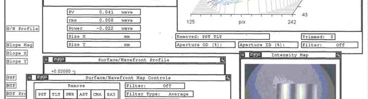
17 Page 17 of 30 Wavefront error (3.8) The total wavefront error measured on the Zygo interferometer is 0.09λ peak to valley, compared to the specified value of 0.05 λ. The figure below shows the transmitted wavefront error. Figure 12: Transmitted wavefront error, 0.09λ peak-to-valley


18 Page 18 of 30 Surface Flatness Measurements Figure 13: Input/Output wave plate surface figure Figure 14: Solid arm wave plate external surface figure


19 Page 19 of 30 Figure 15: Vacuum arm wave plate external surface figure Figure 16: Interferogram of cube surface facing vacuum arm


20 Page 20 of 30 Antireflection coatings (3.9) Vacuum facing surfaces shall be antireflection coated to R < 0.2 % at nm over the central 35 mm diameter at angles from 0 to 5 from the surface normal. A witness from each anti-reflection coating run will be measured to ensure that the reflectance is less than 0.2%. The coating aperture for the anti-reflection coatings on the vacuum arm will have a nominal aperture of 34 mm to allow clearance relative to the vacuum spacer inside diameter of 35 mm. The spatial uniformity of at least one antireflection coating will be tested on the spectrometer system. Coating location Coating ID Notes AR on beam splitter, AR % R at nm vacuum arm wave plate AR coating on polarizer, input/output wave plate AR 2 <0.1% R at nm Figure 17: Measured reflectivity of AR 1
21 Page 21 of 30 Figure 18: Measured reflectivity of AR 2 Silver Coatings The measured reflectivity of the silver coatings on the solid and vacuum arms is greater than 96.5%. The figure below shows the reflectivity of the four coatings applied to HMI 1 and HMI 2.
22 Page 22 of 30 Figure 19: Silver reflector measurement (shows all four mirrors for HMI 1 and HMI 2
23 Page 23 of 30 Surface quality (3.10) All of the optical surfaces of the interferometer are better than the specified scratch dig specification. The input/output wave plate has one visible scratch (20-40 µm wide). Cement (3.11) The following table shows the type of cement used for each interface, and the lot code for the cement. Interface Cement Lot, expiry BSL7Y BSL7Y beam splitter Norland , 2004 Oct 3 BSL7Y crystal quartz Norland , 2004 Oct 3 CaF 2 BSL7Y (wave plate) Norland , 2005 July 12 BSL7Y PVA polarizer Norland 65 Cemented by Lockheed Martin BSL7Y polarizer BSL7Y cube Norland , 2005 May 14 BSL7Y input/output wave plate BSL7Y cube Norland , 2005 May 14 BSL7Y wave plate BSL7Y solid arm Norland , 2005 May 14 BSL7Y solid arm BSL7Y cube Norland , 2005 Sep 23 CaF 2 BSL7Y cube Norland , 2005 Sep 23 This table records the parallelism of the cemented components to the surfaces of the cube. Michelson face Measured parallelism between optic and cube fringes Wedge (arc seconds) Polarizer Input/output wave plate Vacuum arm Solid arm
24 Page 24 of 30 Assembly dimensions and identification (3.12) Overall Dimensions Dimension Measured value (measured in inches, converted to mm) X (wave plate to vacuum arm) Y (polarizer to solid arm) Specification limits mm <64.0 mm mm <65.0 mm Measured with Mitutoyo 3 micrometer , sn Checked with gauge block prior to measurements Z (height) mm 45.0±0.1 mm Mitutoyo 2 micrometer , sn Checked with gauge block prior to measurements Cube dimensions Dimension Measured value Measured with X mm Mitutoyo 2 micrometer 103- Y mm 136, sn Checked with gauge block prior to Z mm measurements Wave Plates Location Serial Number Thickness Maximum error Input/Output # mm λ/550 Vacuum arm # mm λ/520 Solid arm # mm λ/530


25 Page 25 of 30 Wave Plate Thickness Measurements Figure 20: Input/Output wave plate thickness map


26 Page 26 of 30 Figure 21: Vacuum arm wave plate thickness map


27 Page 27 of 30 Figure 22: Solid arm wave plate thickness map
28 Page 28 of 30 Material Certificates, Process Certifications All of the glass used in the HMI Michelson is from the same melt of Ohara BSL7Y glass material cerfificates attached. The wave plate sandwiches and solid arms were made from the 50 mm thick material, while the beam splitters were made from 35 mm thick material. The refractive index deltas are multiplied by 10 5 on the melt data sheets. Figure 23: Material certificate for 35 mm thick Ohara BSL7Y glass Figure 24: Material certificate for 50 mm thick Ohara BSL7Y glass The crystal quartz used in this instrument was supplied by Sawyer Research. The material code is SP The calcium fluoride spacers were fabricated from
29 Page 29 of 30 material supplied by Corning. The material was cut with the <111> crystal axis parallel to the optic axis of the instrument. The material code for the calcium fluoride is The PVA polarizer was assembled from BSL7Y blanks provided by LightMachinery, and PVA polarizer film provided by Lockheed Martin. Assembly of the polarizer sandwiches was performed by Lockheed Martin. AR coatings were applied to our specification CT Silver coatings were applied to our specification CT The polarizing beam splitter coating was applied by Iridian Spectral technologies; their run number #ds-bv b000 bxfs727a. 4.0 List of Coating Witness Samples The following table lists coating witness for all of the coating runs used in fabricating HMI 1 and HMI 2. Coating Witness Identification Polarizing beam splitter July 04 Iridian HMI B/S AR 1 Dec 8/04 AR on B/S + WP #12, #14 AR 2 BSL7Y Lockheed AR witness WP #10, #15 Polarizer Dec 15/04 AR 3 BSL7Y witness for vac arm of cube #2 Feb 23/05 AR 4 BSL7Y witness Mar 1/05 on reworked polarizer/cube HMI 1 solid arm BSL7Y silver witness for mm arm HMI 1 vacuum arm BSL7Y silver witness mm arm HMI 2 solid arm BSL7Y silver witness for mm arm HMI 2 vacuum arm BSL7Y silver witness for mm arm Spare silver coated blanks (for practice cleaning) BK-7 witness Could be used for silver wipe testing
30 Page 30 of 30 This report was prepared by Ian Miller, 2005 May 2 LightMachinery Inc. Director of R&D
PREPARED BY: I. Miller DATE: 2004 May 23 CO-OWNERS REVISED DATE OF ISSUE/CHANGED PAGES
 Page 1 of 30 LIGHTMACHINERY TEST REPORT LQT 30.11-2 TITLE: HMI Michelson Interferometer Test Report Serial Number 2 - Narrowband FSR INSTRUCTION OWNER HMI Project Manager PREPARED BY: I. Miller DATE: 2004
PREPARED BY: I. Miller DATE: 2004 May 23 CO-OWNERS REVISED DATE OF ISSUE/CHANGED PAGES
 Page 1 of 34 LIGHTMACHINERY TEST REPORT LQT 30.11-3 TITLE: HMI Michelson Interferometer Test Report Serial Number 3 wide band FSR INSTRUCTION OWNER HMI Project Manager PREPARED BY: I. Miller DATE: 2004
Beam Splitters. Diameter ET Transmission Reflectance %
 Beam Splitters Beam splitters allow a beam to be split into two beams of differing power, however, the most popular power split is 50:50 at a 45 incidence angle. The polarization needs to be considered
Understanding Optical Specifications
 Understanding Optical Specifications Optics can be found virtually everywhere, from fiber optic couplings to machine vision imaging devices to cutting-edge biometric iris identification systems. Despite
Will contain image distance after raytrace Will contain image height after raytrace
 Name: LASR 51 Final Exam May 29, 2002 Answer all questions. Module numbers are for guidance, some material is from class handouts. Exam ends at 8:20 pm. Ynu Raytracing The first questions refer to the
SELECTION GUIDE MULTIPLE-ORDER QUARTZ WAVEPLATES ZERO-ORDER QUARTZ WAVEPLATES DUAL-WAVELENGTH WAVEPLATES... 85
 WAVEPLATES Mirrors Waveplates are used in applications where the control, synthesis, or analysis of the polarization state of an incident beam of light is required. Our waveplates are constructed of very
EE119 Introduction to Optical Engineering Spring 2003 Final Exam. Name:
 EE119 Introduction to Optical Engineering Spring 2003 Final Exam Name: SID: CLOSED BOOK. THREE 8 1/2 X 11 SHEETS OF NOTES, AND SCIENTIFIC POCKET CALCULATOR PERMITTED. TIME ALLOTTED: 180 MINUTES Fundamental
Physics 431 Final Exam Examples (3:00-5:00 pm 12/16/2009) TIME ALLOTTED: 120 MINUTES Name: Signature:
 TIME ALLOTTED: 120 MINUTES Name: Signature:") Physics 431 Final Exam Examples (3:00-5:00 pm 12/16/2009) TIME ALLOTTED: 120 MINUTES Name: PID: Signature: CLOSED BOOK. TWO 8 1/2 X 11 SHEET OF NOTES (double sided is allowed), AND SCIENTIFIC POCKET CALCULATOR
Physics 431 Final Exam Examples (3:00-5:00 pm 12/16/2009) TIME ALLOTTED: 120 MINUTES Name: PID: Signature: CLOSED BOOK. TWO 8 1/2 X 11 SHEET OF NOTES (double sided is allowed), AND SCIENTIFIC POCKET CALCULATOR
A fast F-number 10.6-micron interferometer arm for transmitted wavefront measurement of optical domes
 A fast F-number 10.6-micron interferometer arm for transmitted wavefront measurement of optical domes Doug S. Peterson, Tom E. Fenton, Teddi A. von Der Ahe * Exotic Electro-Optics, Inc., 36570 Briggs Road,
Agilent 10705A Single Beam Interferometer and Agilent 10704A Retroreflector
 7B Agilent 10705A Single Beam Interferometer and Agilent 10704A Retroreflector Description Description The Agilent 10705A Single Beam Interferometer (shown in Figure 7B-1) is intended for use in low-mass
Spectrograph Lens Fabrication RFQ 22 Jan, 2003
 Spectrograph Lens Fabrication RFQ 22 Jan, 2003 1 Scope of Project This document describes the specifications for the fabrication of 18 optical elements to be used in the Prime Focus Imaging Spectrograph
Physical Optics. Diffraction.
 Physical Optics. Diffraction. Interference Young s interference experiment Thin films Coherence and incoherence Michelson interferometer Wave-like characteristics of light Huygens-Fresnel principle Interference.
CHAPTER 5 FINE-TUNING OF AN ECDL WITH AN INTRACAVITY LIQUID CRYSTAL ELEMENT
 CHAPTER 5 FINE-TUNING OF AN ECDL WITH AN INTRACAVITY LIQUID CRYSTAL ELEMENT In this chapter, the experimental results for fine-tuning of the laser wavelength with an intracavity liquid crystal element
6 THICKNESS MEASUREMENT OF TRANSPARENT MEDIA
 6 THICKNESS MEASUREMENT OF TRANSPARENT MEDIA Measure the Thickness of Transparent Media Using the Mach-Zehnder Interferometer MODEL OEK-100 PROJECT #5 62 6.1 Introduction The thickness of a transparent
Photolithography II ( Part 2 )
") 1 Photolithography II ( Part 2 ) Chapter 14 : Semiconductor Manufacturing Technology by M. Quirk & J. Serda Saroj Kumar Patra, Department of Electronics and Telecommunication, Norwegian University of Science
1 Photolithography II ( Part 2 ) Chapter 14 : Semiconductor Manufacturing Technology by M. Quirk & J. Serda Saroj Kumar Patra, Department of Electronics and Telecommunication, Norwegian University of Science
Filters for Dual Band Infrared Imagers
 Filters for Dual Band Infrared Imagers Thomas D. Rahmlow, Jr.* a, Jeanne E. Lazo-Wasem a, Scott Wilkinson b, and Flemming Tinker c a Rugate Technologies, Inc., 353 Christian Street, Oxford, CT 6478; b
EE119 Introduction to Optical Engineering Fall 2009 Final Exam. Name:
 EE119 Introduction to Optical Engineering Fall 2009 Final Exam Name: SID: CLOSED BOOK. THREE 8 1/2 X 11 SHEETS OF NOTES, AND SCIENTIFIC POCKET CALCULATOR PERMITTED. TIME ALLOTTED: 180 MINUTES Fundamental
Exercise 8: Interference and diffraction
 Physics 223 Name: Exercise 8: Interference and diffraction 1. In a two-slit Young s interference experiment, the aperture (the mask with the two slits) to screen distance is 2.0 m, and a red light of wavelength
COMPANY HISTORY MISSION STATEMENT. 385 Cooper Road West Berlin, NJ USA Phone: Fax:
 COMPANY HISTORY Founded in 1960 to provide synthetic fused silica for military radar applications, Dynasil has become widely recognized in the industry as a reliable supplier of the highest quality optical
StarBright XLT Optical Coatings
 StarBright XLT Optical Coatings StarBright XLT is Celestron s revolutionary optical coating system that outperforms any other coating in the commercial telescope market. Our most popular Schmidt-Cassegrain
Lecture 04: Solar Imaging Instruments
 Hale COLLAGE (NJIT Phys-780) Topics in Solar Observation Techniques Lecture 04: Solar Imaging Instruments Wenda Cao New Jersey Institute of Technology Valentin M. Pillet National Solar Observatory SDO
Test procedures Page: 1 of 5
 Test procedures Page: 1 of 5 1 Scope This part of document establishes uniform requirements for measuring the numerical aperture of optical fibre, thereby assisting in the inspection of fibres and cables
PHY 431 Homework Set #5 Due Nov. 20 at the start of class
 PHY 431 Homework Set #5 Due Nov. 0 at the start of class 1) Newton s rings (10%) The radius of curvature of the convex surface of a plano-convex lens is 30 cm. The lens is placed with its convex side down
MULTI-ELEMENT LENSES. Don t see exactly what you are looking for? CVI Laser Optics specializes in prototype to volume production manufacturing!
 MULTI-ELEMENT LENSES Mirrors Multi-element lenses are an ideal solution for applications requiring specialized performance and/or a high degree of aberration correction. Our line of multi-element lenses
PHYS 3153 Methods of Experimental Physics II O2. Applications of Interferometry
 Purpose PHYS 3153 Methods of Experimental Physics II O2. Applications of Interferometry In this experiment, you will study the principles and applications of interferometry. Equipment and components PASCO
The Design, Fabrication, and Application of Diamond Machined Null Lenses for Testing Generalized Aspheric Surfaces
 The Design, Fabrication, and Application of Diamond Machined Null Lenses for Testing Generalized Aspheric Surfaces James T. McCann OFC - Diamond Turning Division 69T Island Street, Keene New Hampshire
7 WAVEMETER PROJECT #6 MODEL OEK-100. Measure the Wavelength of An Unknown laser Using 633nm and 543 nm HeNe lasers
 7 WAVEMETER Measure the Wavelength of An Unknown laser Using 633nm and 543 nm HeNe lasers MODEL OEK-100 PROJECT #6 72 7.1 Introduction A wavemeter can be constructed with a Twyman-Green interferometer.
Lithography. 3 rd. lecture: introduction. Prof. Yosi Shacham-Diamand. Fall 2004
 Lithography 3 rd lecture: introduction Prof. Yosi Shacham-Diamand Fall 2004 1 List of content Fundamental principles Characteristics parameters Exposure systems 2 Fundamental principles Aerial Image Exposure
New Optics for Astronomical Polarimetry
 New Optics for Astronomical Polarimetry Located in Colorado USA Topics Components for polarization control and polarimetry Organic materials Liquid crystals Birefringent polymers Microstructures Metrology
ECEN. Spectroscopy. Lab 8. copy. constituents HOMEWORK PR. Figure. 1. Layout of. of the
 ECEN 4606 Lab 8 Spectroscopy SUMMARY: ROBLEM 1: Pedrotti 3 12-10. In this lab, you will design, build and test an optical spectrum analyzer and use it for both absorption and emission spectroscopy. The
Chapter Ray and Wave Optics
 109 Chapter Ray and Wave Optics 1. An astronomical telescope has a large aperture to [2002] reduce spherical aberration have high resolution increase span of observation have low dispersion. 2. If two
Tutorial Zemax 9: Physical optical modelling I
 Tutorial Zemax 9: Physical optical modelling I 2012-11-04 9 Physical optical modelling I 1 9.1 Gaussian Beams... 1 9.2 Physical Beam Propagation... 3 9.3 Polarization... 7 9.4 Polarization II... 11 9 Physical
MicroSpot FOCUSING OBJECTIVES
 OFR P R E C I S I O N O P T I C A L P R O D U C T S MicroSpot FOCUSING OBJECTIVES APPLICATIONS Micromachining Microlithography Laser scribing Photoablation MAJOR FEATURES For UV excimer & high-power YAG
Computer Generated Holograms for Optical Testing
 Computer Generated Holograms for Optical Testing Dr. Jim Burge Associate Professor Optical Sciences and Astronomy University of Arizona jburge@optics.arizona.edu 520-621-8182 Computer Generated Holograms
Initial Results from the C-Mod Prototype Polarimeter/Interferometer
 Initial Results from the C-Mod Prototype Polarimeter/Interferometer K. R. Smith, J. Irby, R. Leccacorvi, E. Marmar, R. Murray, R. Vieira October 24-28, 2005 APS-DPP Conference 1 Abstract An FIR interferometer-polarimeter
Practical Guide to Specifying Optical Components
 Practical Guide to Specifying Optical Components OPTI 521 Introduction to Opto-Mechanical Engineering Fall 2012 December 10, 2012 Brian Parris Introduction This paper is intended to serve as a practical
A novel tunable diode laser using volume holographic gratings
 A novel tunable diode laser using volume holographic gratings Christophe Moser *, Lawrence Ho and Frank Havermeyer Ondax, Inc. 85 E. Duarte Road, Monrovia, CA 9116, USA ABSTRACT We have developed a self-aligned
HUYGENS PRINCIPLE AND INTERFERENCE
 HUYGENS PRINCIPLE AND INTERFERENCE VERY SHORT ANSWER QUESTIONS Q-1. Can we perform Double slit experiment with ultraviolet light? Q-2. If no particular colour of light or wavelength is specified, then
Optical Engineering 421/521 Sample Questions for Midterm 1
 Optical Engineering 421/521 Sample Questions for Midterm 1 Short answer 1.) Sketch a pechan prism. Name a possible application of this prism., write the mirror matrix for this prism (or any other common
Using Stock Optics. ECE 5616 Curtis
 Using Stock Optics What shape to use X & Y parameters Please use achromatics Please use camera lens Please use 4F imaging systems Others things Data link Stock Optics Some comments Advantages Time and
Collimation Tester Instructions
 Description Use shear-plate collimation testers to examine and adjust the collimation of laser light, or to measure the wavefront curvature and divergence/convergence magnitude of large-radius optical
Polarization Experiments Using Jones Calculus
 Polarization Experiments Using Jones Calculus Reference http://chaos.swarthmore.edu/courses/physics50_2008/p50_optics/04_polariz_matrices.pdf Theory In Jones calculus, the polarization state of light is
Absentee layer. A layer of dielectric material, transparent in the transmission region of
 Glossary of Terms A Absentee layer. A layer of dielectric material, transparent in the transmission region of the filter, due to a phase thickness of 180. Absorption curve, absorption spectrum. The relative
Dual band antireflection coatings for the infrared
 Dual band antireflection coatings for the infrared Thomas D. Rahmlow, Jr.* a, Jeanne E. Lazo-Wasem a, Scott Wilkinson b, and Flemming Tinker c a Rugate Technologies, Inc., 33 Christian Street, Oxford,
Chapter 17: Wave Optics. What is Light? The Models of Light 1/11/13
 Chapter 17: Wave Optics Key Terms Wave model Ray model Diffraction Refraction Fringe spacing Diffraction grating Thin-film interference What is Light? Light is the chameleon of the physical world. Under
Optical Requirements
 Optical Requirements Transmission vs. Film Thickness A pellicle needs a good light transmission and long term transmission stability. Transmission depends on the film thickness, film material and any anti-reflective
Agilent 10774A Short Range Straightness Optics and Agilent 10775A Long Range Straightness Optics
 7Y Agilent 10774A Short Range Straightness Optics and Agilent 10775A Long Range Straightness Optics Introduction Introduction Straightness measures displacement perpendicular to the axis of intended motion
LECTURE 26: Interference
 ANNOUNCEMENT *Final: Thursday December 14, 2017, 1 PM 3 PM *Location: Elliot Hall of Music *Covers all readings, lectures, homework from Chapters 28.6 through 33. *The exam will be multiple choice. Be
3.0 Alignment Equipment and Diagnostic Tools:
 3.0 Alignment Equipment and Diagnostic Tools: Alignment equipment The alignment telescope and its use The laser autostigmatic cube (LACI) interferometer A pin -- and how to find the center of curvature
Week IX: INTERFEROMETER EXPERIMENTS
 Week IX: INTERFEROMETER EXPERIMENTS Notes on Adjusting the Michelson Interference Caution: Do not touch the mirrors or beam splitters they are front surface and difficult to clean without damaging them.
Aspheric Lenses. Contact us for a Stock or Custom Quote Today! Edmund Optics BROCHURE
 Edmund Optics BROCHURE Aspheric Lenses products & capabilities Contact us for a Stock or Custom Quote Today! USA: +1-856-547-3488 EUROPE: +44 (0) 1904 788600 ASIA: +65 6273 6644 JAPAN: +81-3-3944-6210
From Extended Light Source to Collimated Illumination
 Chapter 2 From Extended Light Source to Collimated Illumination 2.1 Introduction The collimation obtained in the manner shown in Fig. 1.10(b) uses a suitable projection lens with diameter-to-focal-length
Practical Flatness Tech Note
 Practical Flatness Tech Note Understanding Laser Dichroic Performance BrightLine laser dichroic beamsplitters set a new standard for super-resolution microscopy with λ/10 flatness per inch, P-V. We ll
INTERFEROMETER VI-direct
 Universal Interferometers for Quality Control Ideal for Production and Quality Control INTERFEROMETER VI-direct Typical Applications Interferometers are an indispensable measurement tool for optical production
7. Michelson Interferometer
 7. Michelson Interferometer In this lab we are going to observe the interference patterns produced by two spherical waves as well as by two plane waves. We will study the operation of a Michelson interferometer,
TECHNICAL QUICK REFERENCE GUIDE MANUFACTURING CAPABILITIES GLASS PROPERTIES COATING CURVES REFERENCE MATERIALS
 TECHNICAL QUICK REFERENCE GUIDE COATING CURVES GLASS PROPERTIES MANUFACTURING CAPABILITIES REFERENCE MATERIALS TABLE OF CONTENTS Why Edmund Optics?... 3 Anti-Reflective (AR) Coatings... 4-16 Metallic Mirror
Domes Apertures Reticules
 Domes Stock and custom Domes available for a range of underwater, ROV and Pyronometer and high pressure viewport applications. Available in BK7, Silicon, Sapphire, UV Quartz and Acrylic. Custom BK7 glass
Infrared broadband 50%-50% beam splitters for s- polarized light
 University of New Orleans ScholarWorks@UNO Electrical Engineering Faculty Publications Department of Electrical Engineering 7-1-2006 Infrared broadband 50%-50% beam splitters for s- polarized light R.
Department of Mechanical and Aerospace Engineering, Princeton University Department of Astrophysical Sciences, Princeton University ABSTRACT
 Phase and Amplitude Control Ability using Spatial Light Modulators and Zero Path Length Difference Michelson Interferometer Michael G. Littman, Michael Carr, Jim Leighton, Ezekiel Burke, David Spergel
1.6 Beam Wander vs. Image Jitter
 8 Chapter 1 1.6 Beam Wander vs. Image Jitter It is common at this point to look at beam wander and image jitter and ask what differentiates them. Consider a cooperative optical communication system that
Solution of Exercises Lecture Optical design with Zemax Part 6
 2013-06-17 Prof. Herbert Gross Friedrich Schiller University Jena Institute of Applied Physics Albert-Einstein-Str 15 07745 Jena Solution of Exercises Lecture Optical design with Zemax Part 6 6 Illumination
simulations, tests and production
 LIGHT FUNNELS: simulations, tests and production J.A. Aguilar, A. Basili, V. Boccone, A. Christov, M. della Volpe, T. Montaruli, M. Rameez University of Geneva, Switzerland 17/07/2013 alessandro.basili@cern.ch
Chapter 24. The Wave Nature of Light
 Ch-24-1 Chapter 24 The Wave Nature of Light Questions 1. Does Huygens principle apply to sound waves? To water waves? Explain how Huygens principle makes sense for water waves, where each point vibrates
PHYS 1112L - Introductory Physics Laboratory II
 PHYS 1112L - Introductory Physics Laboratory II Laboratory Advanced Sheet Snell's Law 1. Objectives. The objectives of this laboratory are a. to determine the index of refraction of a liquid using Snell's
APPLICATIONS FOR TELECENTRIC LIGHTING
 APPLICATIONS FOR TELECENTRIC LIGHTING Telecentric lenses used in combination with telecentric lighting provide the most accurate results for measurement of object shapes and geometries. They make attributes
IMAGE SENSOR SOLUTIONS. KAC-96-1/5" Lens Kit. KODAK KAC-96-1/5" Lens Kit. for use with the KODAK CMOS Image Sensors. November 2004 Revision 2
 KODAK for use with the KODAK CMOS Image Sensors November 2004 Revision 2 1.1 Introduction Choosing the right lens is a critical aspect of designing an imaging system. Typically the trade off between image
4-2 Image Storage Techniques using Photorefractive
 4-2 Image Storage Techniques using Photorefractive Effect TAKAYAMA Yoshihisa, ZHANG Jiasen, OKAZAKI Yumi, KODATE Kashiko, and ARUGA Tadashi Optical image storage techniques using the photorefractive effect
Angela Piegari ENEA, Optical Coatings Laboratory, Roma, Italy
 Optical Filters for Space Instrumentation Angela Piegari ENEA, Optical Coatings Laboratory, Roma, Italy Trieste, 18 February 2015 Optical Filters Optical Filters are commonly used in Space instruments
NEW NEW NEW NEW NEW NEW. Systems
 Table of Contents Polarization Components Polarizers NEW Retarders NEW NEW Linear Polarizer Principles 3 Precision Linear Polarizers 6 High Contrast Linear Polarizers 8 Ultra-High Contrast Linear Polarizers
Optical Components for Laser Applications. Günter Toesko - Laserseminar BLZ im Dezember
 Günter Toesko - Laserseminar BLZ im Dezember 2009 1 Aberrations An optical aberration is a distortion in the image formed by an optical system compared to the original. It can arise for a number of reasons
MRO Delay Line. Performance of Beam Compressor for Agilent Laser Head INT-406-VEN The Cambridge Delay Line Team. rev 0.
 MRO Delay Line Performance of Beam Compressor for Agilent Laser Head INT-406-VEN-0123 The Cambridge Delay Line Team rev 0.45 1 April 2011 Cavendish Laboratory Madingley Road Cambridge CB3 0HE UK Change
COS NCM2 Mirror Substrate Specification
 Date: Document Number: Revision: Contract No.: NAS5-98043 CDRL No.: N/A Prepared By: E. Wilkinson 2-18-99 E. Wilkinson, COS Instrument Scientist, CU/CASA Date Reviewed By: R. Cahill 2-18-99 R. Cahill,
LEOK-3 Optics Experiment kit
 LEOK-3 Optics Experiment kit Physical optics, geometrical optics and fourier optics Covering 26 experiments Comprehensive documents Include experiment setups, principles and procedures Cost effective solution
CHARA AO Calibration Process
 CHARA AO Calibration Process Judit Sturmann CHARA AO Project Overview Phase I. Under way WFS on telescopes used as tip-tilt detector Phase II. Not yet funded WFS and large DM in place of M4 on telescopes
Interferometer. Instruction Manual and Experiment Guide for the PASCO scientific Model OS /91 Revision B
 Instruction Manual and Experiment Guide for the PASCO Model OS-8501 012-02675 10/91 Revision B Interferometer MODEL OS-8501 INTERFEROMETER Copyright February 1986 $10.00 Interferometer 012-02675B Table
ADVANCED OPTICS LAB -ECEN 5606
 ADVANCED OPTICS LAB -ECEN 5606 Basic Skills Lab Dr. Steve Cundiff and Edward McKenna, 1/15/04 rev KW 1/15/06, 1/8/10 The goal of this lab is to provide you with practice of some of the basic skills needed
Ref No : PUR/GT/IMP/VELC-ADITYA/20/ September 19, 2016.
 Ref No : PUR/GT/IMP/VELC-ADITYA/20/2016-17. September 19, 2016. M/s. Dear Sir/s, The Director, Indian Institute of Astrophysics, Bangalore, invites Sealed Tenders (both price bid & technical bid) for the
FRAUNHOFER AND FRESNEL DIFFRACTION IN ONE DIMENSION
 FRAUNHOFER AND FRESNEL DIFFRACTION IN ONE DIMENSION Revised November 15, 2017 INTRODUCTION The simplest and most commonly described examples of diffraction and interference from two-dimensional apertures
P r i s m s I N D E X
 P r i s m s P r i s m s I N D E X Selection By processing the various forms of glass, the prism produces a special effect due to refraction. Since there is no angular offset that after manufacture, it
ADVANCED OPTICS LAB -ECEN Basic Skills Lab
 ADVANCED OPTICS LAB -ECEN 5606 Basic Skills Lab Dr. Steve Cundiff and Edward McKenna, 1/15/04 Revised KW 1/15/06, 1/8/10 Revised CC and RZ 01/17/14 The goal of this lab is to provide you with practice
Bandpass Edge Dichroic Notch & More
 Edmund Optics BROCHURE Filters COPYRIGHT 217 EDMUND OPTICS, INC. ALL RIGHTS RESERVED 1/17 Bandpass Edge Dichroic Notch & More Contact us for a Stock or Custom Quote Today! USA: +1-856-547-3488 EUROPE:
Multi-Element Overview
 Intro Lenses Overview........ 128 Windows Achromats 425-675nm Cemented Doublets. 132 425-675nm Fast Achromats..... 133 1064/633nm Air-Spaced...... 134 1064/532nm Air-Spaced...... 135 Aplanats Visible....................
2 CYCLICAL SHEARING INTERFEROMETER
 2 CYCLICAL SHEARING INTERFEROMETER Collimation Testing and Measurement of The Radius of Curvature of the Wavefront MODEL OEK-100 PROJECT #1 18 2.1 Introduction In many applications, it is desired to measure
06SurfaceQuality.nb Optics James C. Wyant (2012) 1
 1") 06SurfaceQuality.nb Optics 513 - James C. Wyant (2012) 1 Surface Quality SQ-1 a) How is surface profile data obtained using the FECO interferometer? Your explanation should include diagrams with the appropriate
06SurfaceQuality.nb Optics 513 - James C. Wyant (2012) 1 Surface Quality SQ-1 a) How is surface profile data obtained using the FECO interferometer? Your explanation should include diagrams with the appropriate
Development of C-Mod FIR Polarimeter*
 Development of C-Mod FIR Polarimeter* P.XU, J.H.IRBY, J.BOSCO, A.KANOJIA, R.LECCACORVI, E.MARMAR, P.MICHAEL, R.MURRAY, R.VIEIRA, S.WOLFE (MIT) D.L.BROWER, W.X.DING (UCLA) D.K.MANSFIELD (PPPL) *Supported
APPLICATION NOTE. Understanding the PV Specification. Introduction. Problems with PV
 APPLICATION NOTE Understanding the PV Specification Introduction An array of non-standard, arbitrary practices are frequently used in the optics industry to demonstrate conformance of a part to the traditional
Imaging Systems Laboratory II. Laboratory 8: The Michelson Interferometer / Diffraction April 30 & May 02, 2002
 1051-232 Imaging Systems Laboratory II Laboratory 8: The Michelson Interferometer / Diffraction April 30 & May 02, 2002 Abstract. In the last lab, you saw that coherent light from two different locations
Properties of Structured Light
 Properties of Structured Light Gaussian Beams Structured light sources using lasers as the illumination source are governed by theories of Gaussian beams. Unlike incoherent sources, coherent laser sources
High Performance Thin Film Optical Coatings Technical Reference Document 09/13. Coatings Capabilities. Heat Control - Hot Mirror Filters
 Heat Control - Hot Mirror Filters A hot mirror is in essence a thin film coating applied to substrates in an effort to reflect infra-red radiation either as a means to harness the reflected wavelengths
Dark Field Technologies In-Situ Defect Detection Practical Considerations and Results
 Dark Field Technologies In-Situ Defect Detection Practical Considerations and Results June 21, 2017 In-Situ Defect Detection The need for In-Situ Defect Detection Solid State Laser Reflection Practical
Optical Isolator Tutorial (Page 1 of 2) νlh, where ν, L, and H are as defined below. ν: the Verdet Constant, a property of the
 νlh, where ν, L, and H are as defined below. ν: the Verdet Constant, a property of the") Aspheric Optical Isolator Tutorial (Page 1 of 2) Function An optical isolator is a passive magneto-optic device that only allows light to travel in one direction. Isolators are used to protect a source
Aspheric Optical Isolator Tutorial (Page 1 of 2) Function An optical isolator is a passive magneto-optic device that only allows light to travel in one direction. Isolators are used to protect a source
Southern African Large Telescope. Prime Focus Imaging Spectrograph. Polarimetric Optics Design Study
 Southern African Large Telescope Prime Focus Imaging Spectrograph Polarimetric Optics Design Study Kenneth Nordsieck University of Wisconsin Revision 1.1 5 Oct 2001 SALT PFIS/IMPALAS Polarimetric Optics
R.B.V.R.R. WOMEN S COLLEGE (AUTONOMOUS) Narayanaguda, Hyderabad.
 Narayanaguda, Hyderabad.") R.B.V.R.R. WOMEN S COLLEGE (AUTONOMOUS) Narayanaguda, Hyderabad. DEPARTMENT OF PHYSICS QUESTION BANK FOR SEMESTER III PAPER III OPTICS UNIT I: 1. MATRIX METHODS IN PARAXIAL OPTICS 2. ABERATIONS UNIT II
R.B.V.R.R. WOMEN S COLLEGE (AUTONOMOUS) Narayanaguda, Hyderabad. DEPARTMENT OF PHYSICS QUESTION BANK FOR SEMESTER III PAPER III OPTICS UNIT I: 1. MATRIX METHODS IN PARAXIAL OPTICS 2. ABERATIONS UNIT II
New application of liquid crystal lens of active polarized filter for micro camera
 New application of liquid crystal lens of active polarized filter for micro camera Giichi Shibuya, * Nobuyuki Okuzawa, and Mitsuo Hayashi Department Devices Development Center, Technology Group, TDK Corporation,
Photonics West Contact us for a Stock or Custom Quote Today! Edmund Optics BROCHURE
 Edmund Optics BROHURE Photonics West 2017 Product Highlights Beam Expanders Off-xis Parabolic Mirrors Right ngle Prisms ontact us for a Stock or ustom Quote Today! US: +1-856-547-3488 EUROPE: +44 (0) 1904
Development of a new multi-wavelength confocal surface profilometer for in-situ automatic optical inspection (AOI)
") Development of a new multi-wavelength confocal surface profilometer for in-situ automatic optical inspection (AOI) Liang-Chia Chen 1#, Chao-Nan Chen 1 and Yi-Wei Chang 1 1. Institute of Automation Technology,
Development of a new multi-wavelength confocal surface profilometer for in-situ automatic optical inspection (AOI) Liang-Chia Chen 1#, Chao-Nan Chen 1 and Yi-Wei Chang 1 1. Institute of Automation Technology,
Be aware that there is no universal notation for the various quantities.
 Fourier Optics v2.4 Ray tracing is limited in its ability to describe optics because it ignores the wave properties of light. Diffraction is needed to explain image spatial resolution and contrast and
Flat Top, Ultra-Narrow Band Pass Optical Filters Using Plasma Deposited Hard Oxide Coatings
 Flat Top, Ultra-Narrow Band Pass Optical Filters Using Plasma Deposited Hard Oxide Coatings Alluxa Engineering Staff September 2012 0 1 0.1 1 cav 2 cav 3 cav 4 cav 5 cav 0.01 0.001 635 636 637 638 639
Why is There a Black Dot when Defocus = 1λ?
 Why is There a Black Dot when Defocus = 1λ? W = W 020 = a 020 ρ 2 When a 020 = 1λ Sag of the wavefront at full aperture (ρ = 1) = 1λ Sag of the wavefront at ρ = 0.707 = 0.5λ Area of the pupil from ρ =
2. Refraction and Reflection
 2. Refraction and Reflection In this lab we will observe the displacement of a light beam by a parallel plate due to refraction. We will determine the refractive index of some liquids from the incident