simulations, tests and production
|
|
|
- Gwendoline Carr
- 5 years ago
- Views:
Transcription


1 LIGHT FUNNELS: simulations, tests and production J.A. Aguilar, A. Basili, V. Boccone, A. Christov, M. della Volpe, T. Montaruli, M. Rameez University of Geneva, Switzerland 17/07/2013 1


2 Open Cone Design Values are constrained by the telescope design: TOP PSF angular pixel size top physical size f/d and Camera diameter Cutoff angle 26.8 mm 13.4 mm mm Dimensions: Angular pixel size: 0.25 Cutoff angle: 24 Length: 36.7 mm 10.9 mm 5.5 mm 9.4 mm BOTTOM Comp. Factor: ~6 2


3 Simulations All simulations done with Zemax, an optical and illumination design software Efficiency is calculated as the ratio between the light recorded on the top/bottom detectors for different incident angles of light. Source spectrum uses the Cherenkov spectrum convoluted to the SiPM response. SiPM window (n = 1.41) or air (n=1) 3

4 Shape Optimization Bèzier curves (1) Image from: A. Okumura (2012) arxiv: P3 line optimized Bèzier object created in C and imported as DLL to ZEMAX Merit function (in red) 4
5 Shape Optimization Bèzier curves (2) Bèzier shape reduces the amount of light transmitted beyond cut-off ~40% more than parabolic. 5
6 Coating Simulation Reflectivity Al+dichroic filter (by Thin Film Physics AG) Simulated transmission curve with several types of reflectors and cone shapes. A comparison with full PMMA cone is also shown. Refractive index s angular dependency is a key factor to take into account for best performances. 6
 reflect on the cone at angles > 40 Coating must be optimized for angles accordingly.")
7 Angular dependency Not all material under study has data with angular dependency. Tests with ellipsometer are foreseen. Distribution of rays on the sensor Distribution of rays on the cone All incident rays within cutoff angle (0-24 ) reflect on the cone at angles > 40 Coating must be optimized for angles accordingly. The curved shape of the cone makes the coating process extremely challenging and a rather complex verification sample must be used to optimize the coating parameters 7
8 Test Setup (1) LED Splitter Diffuser PhotoDiode Diaphragm Focusing lens Aperture 0.5 mm Focusing lens Motorized Rotating Support Collimation of the beam has been verified measuring it s size at several distances. Uniformity of the beam is reasonably good if distance of the target is within cm. Image from: L. Platos (2012) 8


9 Test Setup (2) The goal of the optical setup is to measured the collection efficiency. Two steps measurement: 1. measure light collected by a large area pin diode placed at the entrance window of the concentrator 2. measure light at the end of the light concentrator The ratio between the two measurements, as a function of the angle, give us the collection efficiency: 9


10 Measurements (1) First measurements on a coated sample: 1. Non optimal surface roughness 2. Parabolic shape Systematic errors from instrumentation not included. X-axis bars represent bin size. changing plane of rotation shows some differences 10
11 Measurements (2) Measurements done at smaller wavelengths: 1. Verify coating behaviour 2. Allow optimization of dichroic layers A close interaction with industrial partners may lead to fine tuning of the coating process. Systematic errors from instrumentation not included. X-axis bars represent bin size. 11
12 Quality of the cone Measurements on uncoated cone: 1. to monitor anomalies between faces 2. to estimate the quality of the surface roughness Nearly 20% of transmitted light reaches the sensor without any reflection. Tests on better polished samples are currently on going 12
13 Alignment issue ~0.5 deg ~0.03 deg Current (A) Current (A) Before zeroing After zeroing CR1-Z7E (from Thorlabs) presents a backlash < 1 arcmin, but does not have a zero. Alignment is carried out with a pin-hole ( mm) in front of the sensor and fitting with a gaussian. Mounting and unmounting the mechanical support may lead to misalignment between the two steps. 13


14 Upgraded mechanical support In order to study coating uniformity a new supporting structure has been designed and is currently under production in our mechanical workshop 14


15 Production fast prototyping In order to do a first check of the cone design we chose a fast prototyping technique: 1. Steel master with 3D printing 2. Silicone mold from master to reproduce max. 20 halves. 3. Polyurethane material manually injected. To get a mirror like surface, ready for coating, the master has been manually polished. This technique, if properly applied, would easily guarantee a surface roughness of less than 50 nm. 15
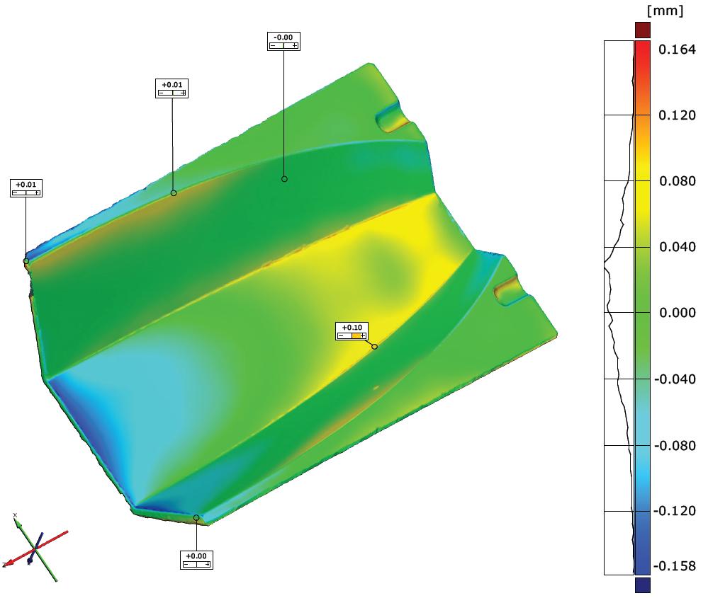
16 Production photogrammetry 16
17 Production coating and plastic Coating: currently in contact with: 1. Thin Film Physics AG (CH) 2. BTE (DE) 3. Savimex (FR) Set of requirements needed: Plastic: currently in contact with: 1. Initial (FR) 2. ViaOptics (DE) 3. Savimex (FR) 4. Gaggione (1) (FR) (1) no black policarbonate available Silicon is a pollutant in the coating process which should be avoided at all costs! An injection molding process is required. 17
Tutorial Zemax 9: Physical optical modelling I
 Tutorial Zemax 9: Physical optical modelling I 2012-11-04 9 Physical optical modelling I 1 9.1 Gaussian Beams... 1 9.2 Physical Beam Propagation... 3 9.3 Polarization... 7 9.4 Polarization II... 11 9 Physical
CHARA AO Calibration Process
 CHARA AO Calibration Process Judit Sturmann CHARA AO Project Overview Phase I. Under way WFS on telescopes used as tip-tilt detector Phase II. Not yet funded WFS and large DM in place of M4 on telescopes
Image Formation. Light from distant things. Geometrical optics. Pinhole camera. Chapter 36
 Light from distant things Chapter 36 We learn about a distant thing from the light it generates or redirects. The lenses in our eyes create images of objects our brains can process. This chapter concerns
ECEN 4606, UNDERGRADUATE OPTICS LAB
 ECEN 4606, UNDERGRADUATE OPTICS LAB Lab 2: Imaging 1 the Telescope Original Version: Prof. McLeod SUMMARY: In this lab you will become familiar with the use of one or more lenses to create images of distant
Section 2 concludes that a glare meter based on a digital camera is probably too expensive to develop and produce, and may not be simple in use.
 Possible development of a simple glare meter Kai Sørensen, 17 September 2012 Introduction, summary and conclusion Disability glare is sometimes a problem in road traffic situations such as: - at road works
Design Description Document
 UNIVERSITY OF ROCHESTER Design Description Document Flat Output Backlit Strobe Dare Bodington, Changchen Chen, Nick Cirucci Customer: Engineers: Advisor committee: Sydor Instruments Dare Bodington, Changchen
Exercise 8: Interference and diffraction
 Physics 223 Name: Exercise 8: Interference and diffraction 1. In a two-slit Young s interference experiment, the aperture (the mask with the two slits) to screen distance is 2.0 m, and a red light of wavelength
IV Assembly and Automation of the SPR Spectrometer
 IV Assembly and Automation of the SPR Spectrometer This chapter is dedicated to the description of the experimental set-up and the procedure used to perform SPR measurements. We start with a schematic
IMAGE SENSOR SOLUTIONS. KAC-96-1/5" Lens Kit. KODAK KAC-96-1/5" Lens Kit. for use with the KODAK CMOS Image Sensors. November 2004 Revision 2
 KODAK for use with the KODAK CMOS Image Sensors November 2004 Revision 2 1.1 Introduction Choosing the right lens is a critical aspect of designing an imaging system. Typically the trade off between image
Week IV: FIRST EXPERIMENTS WITH THE ADVANCED OPTICS SET
 Week IV: FIRST EXPERIMENTS WITH THE ADVANCED OPTICS SET The Advanced Optics set consists of (A) Incandescent Lamp (B) Laser (C) Optical Bench (with magnetic surface and metric scale) (D) Component Carriers
Laser Beam Analysis Using Image Processing
 Journal of Computer Science 2 (): 09-3, 2006 ISSN 549-3636 Science Publications, 2006 Laser Beam Analysis Using Image Processing Yas A. Alsultanny Computer Science Department, Amman Arab University for
Radial Polarization Converter With LC Driver USER MANUAL
 ARCoptix Radial Polarization Converter With LC Driver USER MANUAL Arcoptix S.A Ch. Trois-portes 18 2000 Neuchâtel Switzerland Mail: info@arcoptix.com Tel: ++41 32 731 04 66 Principle of the radial polarization
Polarization Experiments Using Jones Calculus
 Polarization Experiments Using Jones Calculus Reference http://chaos.swarthmore.edu/courses/physics50_2008/p50_optics/04_polariz_matrices.pdf Theory In Jones calculus, the polarization state of light is
Will contain image distance after raytrace Will contain image height after raytrace
 Name: LASR 51 Final Exam May 29, 2002 Answer all questions. Module numbers are for guidance, some material is from class handouts. Exam ends at 8:20 pm. Ynu Raytracing The first questions refer to the
2.2 Wavefront Sensor Design. Lauren H. Schatz, Oli Durney, Jared Males
 Page: 1 of 8 Lauren H. Schatz, Oli Durney, Jared Males 1 Pyramid Wavefront Sensor Overview The MagAO-X system uses a pyramid wavefront sensor (PWFS) for high order wavefront sensing. The wavefront sensor
PREPARED BY: I. Miller DATE: 2004 May 23 CO-OWNERS REVISED DATE OF ISSUE/CHANGED PAGES
 Page 1 of 30 LIGHTMACHINERY TEST REPORT LQT 30.11-1 TITLE: HMI Michelson Interferometer Test Report Serial Number 1 - Wideband FSR INSTRUCTION OWNER HMI Project Manager PREPARED BY: I. Miller DATE: 2004
PREPARED BY: I. Miller DATE: 2004 May 23 CO-OWNERS REVISED DATE OF ISSUE/CHANGED PAGES
 Page 1 of 30 LIGHTMACHINERY TEST REPORT LQT 30.11-2 TITLE: HMI Michelson Interferometer Test Report Serial Number 2 - Narrowband FSR INSTRUCTION OWNER HMI Project Manager PREPARED BY: I. Miller DATE: 2004
2. Refraction and Reflection
 2. Refraction and Reflection In this lab we will observe the displacement of a light beam by a parallel plate due to refraction. We will determine the refractive index of some liquids from the incident
MASSACHUSETTS INSTITUTE OF TECHNOLOGY Mechanical Engineering Department. 2.71/2.710 Final Exam. May 21, Duration: 3 hours (9 am-12 noon)
") MASSACHUSETTS INSTITUTE OF TECHNOLOGY Mechanical Engineering Department 2.71/2.710 Final Exam May 21, 2013 Duration: 3 hours (9 am-12 noon) CLOSED BOOK Total pages: 5 Name: PLEASE RETURN THIS BOOKLET WITH
MASSACHUSETTS INSTITUTE OF TECHNOLOGY Mechanical Engineering Department 2.71/2.710 Final Exam May 21, 2013 Duration: 3 hours (9 am-12 noon) CLOSED BOOK Total pages: 5 Name: PLEASE RETURN THIS BOOKLET WITH
Lecture Notes 10 Image Sensor Optics. Imaging optics. Pixel optics. Microlens
 Lecture Notes 10 Image Sensor Optics Imaging optics Space-invariant model Space-varying model Pixel optics Transmission Vignetting Microlens EE 392B: Image Sensor Optics 10-1 Image Sensor Optics Microlens
AgilOptics mirrors increase coupling efficiency into a 4 µm diameter fiber by 750%.
 Application Note AN004: Fiber Coupling Improvement Introduction AgilOptics mirrors increase coupling efficiency into a 4 µm diameter fiber by 750%. Industrial lasers used for cutting, welding, drilling,
ptical Short Course International
 ptical Short Course International 6679 N. Calle de Calipso, Tucson, AZ www.oscintl.com 520-797-9744 What s Inside The Box? Optics of Digital Projectors Weekly Newsletter Sponsored By: The Brand for highest
Diffractive Axicon application note
 Diffractive Axicon application note. Introduction 2. General definition 3. General specifications of Diffractive Axicons 4. Typical applications 5. Advantages of the Diffractive Axicon 6. Principle of
Computer Generated Holograms for Optical Testing
 Computer Generated Holograms for Optical Testing Dr. Jim Burge Associate Professor Optical Sciences and Astronomy University of Arizona jburge@optics.arizona.edu 520-621-8182 Computer Generated Holograms
NIRCam Optical Analysis
 NIRCam Optical Analysis Yalan Mao, Lynn W. Huff and Zachary A. Granger Lockheed Martin Advanced Technology Center, 3251 Hanover St., Palo Alto, CA 94304 ABSTRACT The Near Infrared Camera (NIRCam) instrument
Optics for the 90 GHz GBT array
 Optics for the 90 GHz GBT array Introduction The 90 GHz array will have 64 TES bolometers arranged in an 8 8 square, read out using 8 SQUID multiplexers. It is designed as a facility instrument for the
Solution of Exercises Lecture Optical design with Zemax Part 6
 2013-06-17 Prof. Herbert Gross Friedrich Schiller University Jena Institute of Applied Physics Albert-Einstein-Str 15 07745 Jena Solution of Exercises Lecture Optical design with Zemax Part 6 6 Illumination
Measurement and alignment of linear variable filters
 Measurement and alignment of linear variable filters Rob Sczupak, Markus Fredell, Tim Upton, Tom Rahmlow, Sheetal Chanda, Gregg Jarvis, Sarah Locknar, Florin Grosu, Terry Finnell and Robert Johnson Omega
Examination Optoelectronic Communication Technology. April 11, Name: Student ID number: OCT1 1: OCT 2: OCT 3: OCT 4: Total: Grade:
 Examination Optoelectronic Communication Technology April, 26 Name: Student ID number: OCT : OCT 2: OCT 3: OCT 4: Total: Grade: Declaration of Consent I hereby agree to have my exam results published on
Laser Scanning 3D Display with Dynamic Exit Pupil
 Koç University Laser Scanning 3D Display with Dynamic Exit Pupil Kishore V. C., Erdem Erden and Hakan Urey Dept. of Electrical Engineering, Koç University, Istanbul, Turkey Hadi Baghsiahi, Eero Willman,
Mirrors. Plano and Spherical. Mirrors. Published on II-VI Infrared
 Page 1 of 13 Published on II-VI Infrared Plano and Spherical or total reflectors are used in laser cavities as rear reflectors and fold mirrors, and externally as beam benders in beam delivery systems.
Figure 7 Dynamic range expansion of Shack- Hartmann sensor using a spatial-light modulator
 Figure 4 Advantage of having smaller focal spot on CCD with super-fine pixels: Larger focal point compromises the sensitivity, spatial resolution, and accuracy. Figure 1 Typical microlens array for Shack-Hartmann
PHY 431 Homework Set #5 Due Nov. 20 at the start of class
 PHY 431 Homework Set #5 Due Nov. 0 at the start of class 1) Newton s rings (10%) The radius of curvature of the convex surface of a plano-convex lens is 30 cm. The lens is placed with its convex side down
Supplementary Materials
 Supplementary Materials In the supplementary materials of this paper we discuss some practical consideration for alignment of optical components to help unexperienced users to achieve a high performance
PREPARED BY: I. Miller DATE: 2004 May 23 CO-OWNERS REVISED DATE OF ISSUE/CHANGED PAGES
 Page 1 of 34 LIGHTMACHINERY TEST REPORT LQT 30.11-3 TITLE: HMI Michelson Interferometer Test Report Serial Number 3 wide band FSR INSTRUCTION OWNER HMI Project Manager PREPARED BY: I. Miller DATE: 2004
Chapter 34 Geometric Optics
 Chapter 34 Geometric Optics Lecture by Dr. Hebin Li Goals of Chapter 34 To see how plane and curved mirrors form images To learn how lenses form images To understand how a simple image system works Reflection
Assembly and Experimental Characterization of Fiber Collimators for Low Loss Coupling
 Assembly and Experimental Characterization of Fiber Collimators for Low Loss Coupling Ruby Raheem Dept. of Physics, Heriot Watt University, Edinburgh, Scotland EH14 4AS, UK ABSTRACT The repeatability of
EXPRIMENT 3 COUPLING FIBERS TO SEMICONDUCTOR SOURCES
 EXPRIMENT 3 COUPLING FIBERS TO SEMICONDUCTOR SOURCES OBJECTIVES In this lab, firstly you will learn to couple semiconductor sources, i.e., lightemitting diodes (LED's), to optical fibers. The coupling
Physics 431 Final Exam Examples (3:00-5:00 pm 12/16/2009) TIME ALLOTTED: 120 MINUTES Name: Signature:
 TIME ALLOTTED: 120 MINUTES Name: Signature:") Physics 431 Final Exam Examples (3:00-5:00 pm 12/16/2009) TIME ALLOTTED: 120 MINUTES Name: PID: Signature: CLOSED BOOK. TWO 8 1/2 X 11 SHEET OF NOTES (double sided is allowed), AND SCIENTIFIC POCKET CALCULATOR
Physics 431 Final Exam Examples (3:00-5:00 pm 12/16/2009) TIME ALLOTTED: 120 MINUTES Name: PID: Signature: CLOSED BOOK. TWO 8 1/2 X 11 SHEET OF NOTES (double sided is allowed), AND SCIENTIFIC POCKET CALCULATOR
Chapter Ray and Wave Optics
 109 Chapter Ray and Wave Optics 1. An astronomical telescope has a large aperture to [2002] reduce spherical aberration have high resolution increase span of observation have low dispersion. 2. If two
X-ray generation by femtosecond laser pulses and its application to soft X-ray imaging microscope
 X-ray generation by femtosecond laser pulses and its application to soft X-ray imaging microscope Kenichi Ikeda 1, Hideyuki Kotaki 1 ' 2 and Kazuhisa Nakajima 1 ' 2 ' 3 1 Graduate University for Advanced
Lens Design I. Lecture 3: Properties of optical systems II Herbert Gross. Summer term
 Lens Design I Lecture 3: Properties of optical systems II 205-04-8 Herbert Gross Summer term 206 www.iap.uni-jena.de 2 Preliminary Schedule 04.04. Basics 2.04. Properties of optical systrems I 3 8.04.
Angular Drift of CrystalTech (1064nm, 80MHz) AOMs due to Thermal Transients. Alex Piggott
 AOMs due to Thermal Transients. Alex Piggott") Angular Drift of CrystalTech 38 197 (164nm, 8MHz) AOMs due to Thermal Transients Alex Piggott July 5, 21 1 .1 General Overview of Findings The AOM was found to exhibit significant thermal drift effects,
Angular Drift of CrystalTech 38 197 (164nm, 8MHz) AOMs due to Thermal Transients Alex Piggott July 5, 21 1 .1 General Overview of Findings The AOM was found to exhibit significant thermal drift effects,
Design of a light-guide used for the real-time monitoring of LCD-displays
 Design of a light-guide used for the real-time monitoring of LCD-displays W. Meulebroeck *a, Y. Meuret a, C. Ruwisch a, T. Kimpe b, P. Vandenberghe b, H. Thienpont a a Vrije Universiteit Brussel, Dept.
Name:.. KSU ID:. Date:././201..
 Name:.. KSU ID:. Date:././201.. Objective (1): Verification of law of reflection and determination of refractive index of Acrylic glass Required Equipment: (i) Optical bench, (ii) Glass lens, mounted,
A novel tunable diode laser using volume holographic gratings
 A novel tunable diode laser using volume holographic gratings Christophe Moser *, Lawrence Ho and Frank Havermeyer Ondax, Inc. 85 E. Duarte Road, Monrovia, CA 9116, USA ABSTRACT We have developed a self-aligned
A Possible Design of Large Angle Beamstrahlung Detector for CESR
 A Possible Design of Large Angle Beamstrahlung Detector for CESR Gang Sun Wayne State University, Detroit MI 482 June 4, 1998 1 Introduction Beamstrahlung radiation occurs when high energy electron and
BEAM HALO OBSERVATION BY CORONAGRAPH
 BEAM HALO OBSERVATION BY CORONAGRAPH T. Mitsuhashi, KEK, TSUKUBA, Japan Abstract We have developed a coronagraph for the observation of the beam halo surrounding a beam. An opaque disk is set in the beam
Tutorial Zemax Introduction 1
 Tutorial Zemax Introduction 1 2012-07-17 1 Introduction 1 1.1 Exercise 1-1: Stair-mirror-setup... 1 1.2 Exercise 1-2: Symmetrical 4f-system... 5 1 Introduction 1.1 Exercise 1-1: Stair-mirror-setup Setup
Chapter 17: Wave Optics. What is Light? The Models of Light 1/11/13
 Chapter 17: Wave Optics Key Terms Wave model Ray model Diffraction Refraction Fringe spacing Diffraction grating Thin-film interference What is Light? Light is the chameleon of the physical world. Under
EE119 Introduction to Optical Engineering Spring 2003 Final Exam. Name:
 EE119 Introduction to Optical Engineering Spring 2003 Final Exam Name: SID: CLOSED BOOK. THREE 8 1/2 X 11 SHEETS OF NOTES, AND SCIENTIFIC POCKET CALCULATOR PERMITTED. TIME ALLOTTED: 180 MINUTES Fundamental
Guide to SPEX Optical Spectrometer
 Guide to SPEX Optical Spectrometer GENERAL DESCRIPTION A spectrometer is a device for analyzing an input light beam into its constituent wavelengths. The SPEX model 1704 spectrometer covers a range from
Optics Laboratory Spring Semester 2017 University of Portland
 Optics Laboratory Spring Semester 2017 University of Portland Laser Safety Warning: The HeNe laser can cause permanent damage to your vision. Never look directly into the laser tube or at a reflection
Absolute Measurements of Light Focused by a Reflector into its Focal Plane
 Absolute Measurements of Light Focused by a Reflector into its Focal Plane Hanna Kellermann, Markus Garczarczyk, Cornelia Schulz, Maxim Shayduk, Jürgen Hose, Razmik Mirzoyan, Masahiro Teshima The MAGIC
Spatially Resolved Backscatter Ceilometer
 Spatially Resolved Backscatter Ceilometer Design Team Hiba Fareed, Nicholas Paradiso, Evan Perillo, Michael Tahan Design Advisor Prof. Gregory Kowalski Sponsor, Spectral Sciences Inc. Steve Richstmeier,
APPLICATIONS FOR TELECENTRIC LIGHTING
 APPLICATIONS FOR TELECENTRIC LIGHTING Telecentric lenses used in combination with telecentric lighting provide the most accurate results for measurement of object shapes and geometries. They make attributes
Multiband Solar Concentrator using Transmissive Dichroic Beamsplitting
 Multiband Solar Concentrator using Transmissive Dichroic Beamsplitting Jason H. Karp and Joseph E. Ford Photonics Systems Integration Lab University of California, San Diego Jacobs School of Engineering
EP 324 Applied Optics. Topic 3 Lenses. Department of Engineering of Physics Gaziantep University. Oct Sayfa 1
 EP 324 Applied Optics Topic 3 Lenses Department of Engineering of Physics Gaziantep University Oct 205 Sayfa PART I SPHERICAL LENSES Sayfa 2 Lens: The main instrument for image formation Sayfa 3 Lens A
Cameras, lenses and sensors
 Cameras, lenses and sensors Marc Pollefeys COMP 256 Cameras, lenses and sensors Camera Models Pinhole Perspective Projection Affine Projection Camera with Lenses Sensing The Human Eye Reading: Chapter.
Industrial Automation
 OPTICAL FIBER. SINGLEMODE OR MULTIMODE It is important to understand the differences between singlemode and multimode fiber optics before selecting one or the other at the start of a project. Its different
Department of Mechanical and Aerospace Engineering, Princeton University Department of Astrophysical Sciences, Princeton University ABSTRACT
 Phase and Amplitude Control Ability using Spatial Light Modulators and Zero Path Length Difference Michelson Interferometer Michael G. Littman, Michael Carr, Jim Leighton, Ezekiel Burke, David Spergel
ADALAM Sensor based adaptive laser micromachining using ultrashort pulse lasers for zero-failure manufacturing D2.2. Ger Folkersma (Demcon)
") D2.2 Automatic adjustable reference path system Document Coordinator: Contributors: Dissemination: Keywords: Ger Folkersma (Demcon) Ger Folkersma, Kevin Voss, Marvin Klein (Demcon) Public Reference path,
D2.2 Automatic adjustable reference path system Document Coordinator: Contributors: Dissemination: Keywords: Ger Folkersma (Demcon) Ger Folkersma, Kevin Voss, Marvin Klein (Demcon) Public Reference path,
A novel solution for various monitoring applications at CERN
 A novel solution for various monitoring applications at CERN F. Lackner, P. H. Osanna 1, W. Riegler, H. Kopetz CERN, European Organisation for Nuclear Research, CH-1211 Geneva-23, Switzerland 1 Department
Fiber Optic Communications
 Fiber Optic Communications ( Chapter 2: Optics Review ) presented by Prof. Kwang-Chun Ho 1 Section 2.4: Numerical Aperture Consider an optical receiver: where the diameter of photodetector surface area
ECEN 4606, UNDERGRADUATE OPTICS LAB
 ECEN 4606, UNDERGRADUATE OPTICS LAB Lab 3: Imaging 2 the Microscope Original Version: Professor McLeod SUMMARY: In this lab you will become familiar with the use of one or more lenses to create highly
Lens Design I. Lecture 3: Properties of optical systems II Herbert Gross. Summer term
 Lens Design I Lecture 3: Properties of optical systems II 207-04-20 Herbert Gross Summer term 207 www.iap.uni-jena.de 2 Preliminary Schedule - Lens Design I 207 06.04. Basics 2 3.04. Properties of optical
Howie's Laser Collimator Instructions:
 Howie's Laser Collimator Instructions: WARNING: AVOID DIRECT OR MIRROR REFLECTED EYE EXPOSURE TO LASER BEAM The laser collimator is a tool that enables precise adjustment of the alignment of telescope
Week IX: INTERFEROMETER EXPERIMENTS
 Week IX: INTERFEROMETER EXPERIMENTS Notes on Adjusting the Michelson Interference Caution: Do not touch the mirrors or beam splitters they are front surface and difficult to clean without damaging them.
Chapter 25. Optical Instruments
 Chapter 25 Optical Instruments Optical Instruments Analysis generally involves the laws of reflection and refraction Analysis uses the procedures of geometric optics To explain certain phenomena, the wave
Optical Design with Zemax
 Optical Design with Zemax Lecture : Correction II 3--9 Herbert Gross Summer term www.iap.uni-jena.de Correction II Preliminary time schedule 6.. Introduction Introduction, Zemax interface, menues, file
EE119 Introduction to Optical Engineering Fall 2009 Final Exam. Name:
 EE119 Introduction to Optical Engineering Fall 2009 Final Exam Name: SID: CLOSED BOOK. THREE 8 1/2 X 11 SHEETS OF NOTES, AND SCIENTIFIC POCKET CALCULATOR PERMITTED. TIME ALLOTTED: 180 MINUTES Fundamental
Systems Biology. Optical Train, Köhler Illumination
 McGill University Life Sciences Complex Imaging Facility Systems Biology Microscopy Workshop Tuesday December 7 th, 2010 Simple Lenses, Transmitted Light Optical Train, Köhler Illumination What Does a
EE119 Introduction to Optical Engineering Spring 2002 Final Exam. Name:
 EE119 Introduction to Optical Engineering Spring 2002 Final Exam Name: SID: CLOSED BOOK. FOUR 8 1/2 X 11 SHEETS OF NOTES, AND SCIENTIFIC POCKET CALCULATOR PERMITTED. TIME ALLOTTED: 180 MINUTES Fundamental
Micro-Optic Solar Concentration and Next-Generation Prototypes
 Micro-Optic Solar Concentration and Next-Generation Prototypes Jason H. Karp, Eric J. Tremblay and Joseph E. Ford Photonics Systems Integration Lab University of California San Diego Jacobs School of Engineering
Classical Optical Solutions
 Petzval Lens Enter Petzval, a Hungarian mathematician. To pursue a prize being offered for the development of a wide-field fast lens system he enlisted Hungarian army members seeing a distraction from
Light sources can be natural or artificial (man-made)
") Light The Sun is our major source of light Light sources can be natural or artificial (man-made) People and insects do not see the same type of light - people see visible light - insects see ultraviolet
Light The Sun is our major source of light Light sources can be natural or artificial (man-made) People and insects do not see the same type of light - people see visible light - insects see ultraviolet
VC 11/12 T2 Image Formation
 VC 11/12 T2 Image Formation Mestrado em Ciência de Computadores Mestrado Integrado em Engenharia de Redes e Sistemas Informáticos Miguel Tavares Coimbra Outline Computer Vision? The Human Visual System
Where Image Quality Begins
 Where Image Quality Begins Filters are a Necessity Not an Accessory Inexpensive Insurance Policy for the System The most cost effective way to improve repeatability and stability in any machine vision
Experiment 1: Fraunhofer Diffraction of Light by a Single Slit
 Experiment 1: Fraunhofer Diffraction of Light by a Single Slit Purpose 1. To understand the theory of Fraunhofer diffraction of light at a single slit and at a circular aperture; 2. To learn how to measure
Criteria for Optical Systems: Optical Path Difference How do we determine the quality of a lens system? Several criteria used in optical design
 Criteria for Optical Systems: Optical Path Difference How do we determine the quality of a lens system? Several criteria used in optical design Computer Aided Design Several CAD tools use Ray Tracing (see
An Indian Journal FULL PAPER. Trade Science Inc. Parameters design of optical system in transmitive star simulator ABSTRACT KEYWORDS
 [Type text] [Type text] [Type text] ISSN : 0974-7435 Volume 10 Issue 23 BioTechnology 2014 An Indian Journal FULL PAPER BTAIJ, 10(23), 2014 [14257-14264] Parameters design of optical system in transmitive
VC 16/17 TP2 Image Formation
 VC 16/17 TP2 Image Formation Mestrado em Ciência de Computadores Mestrado Integrado em Engenharia de Redes e Sistemas Informáticos Hélder Filipe Pinto de Oliveira Outline Computer Vision? The Human Visual
Chapter 3. Introduction to Zemax. 3.1 Introduction. 3.2 Zemax
 Chapter 3 Introduction to Zemax 3.1 Introduction Ray tracing is practical only for paraxial analysis. Computing aberrations and diffraction effects are time consuming. Optical Designers need some popular
Technical Notes. Introduction. Optical Properties. Issue 6 July Figure 1. Specular Reflection:
 Technical Notes This Technical Note introduces basic concepts in optical design for low power off-grid lighting products and suggests ways to improve optical efficiency. It is intended for manufacturers,
High Performance Thin Film Optical Coatings Technical Reference Document 09/13. Coatings Capabilities. Heat Control - Hot Mirror Filters
 Heat Control - Hot Mirror Filters A hot mirror is in essence a thin film coating applied to substrates in an effort to reflect infra-red radiation either as a means to harness the reflected wavelengths
Laser Telemetric System (Metrology)
") Laser Telemetric System (Metrology) Laser telemetric system is a non-contact gauge that measures with a collimated laser beam (Refer Fig. 10.26). It measure at the rate of 150 scans per second. It basically
Laser Telemetric System (Metrology) Laser telemetric system is a non-contact gauge that measures with a collimated laser beam (Refer Fig. 10.26). It measure at the rate of 150 scans per second. It basically
Optical Components for Laser Applications. Günter Toesko - Laserseminar BLZ im Dezember
 Günter Toesko - Laserseminar BLZ im Dezember 2009 1 Aberrations An optical aberration is a distortion in the image formed by an optical system compared to the original. It can arise for a number of reasons
Sequential Ray Tracing. Lecture 2
 Sequential Ray Tracing Lecture 2 Sequential Ray Tracing Rays are traced through a pre-defined sequence of surfaces while travelling from the object surface to the image surface. Rays hit each surface once
Omni-directional Free Space Optical Laser Communication MERIT Kenneth Tukei. University of Maryland, College Park. Maryland Optics Group
 Omni-directional Free Space Optical Laser Communication MERIT 2007 Kenneth Tukei University of Maryland, College Park Dr. Christopher Davis Faculty Advisor Navik Agrawal Graduate Student Advisor Maryland
Opti 415/515. Introduction to Optical Systems. Copyright 2009, William P. Kuhn
 Opti 415/515 Introduction to Optical Systems 1 Optical Systems Manipulate light to form an image on a detector. Point source microscope Hubble telescope (NASA) 2 Fundamental System Requirements Application
Slit. Spectral Dispersion
 Testing Method of Off-axis Parabolic Cylinder Mirror for FIMS K. S. Ryu a,j.edelstein b, J. B. Song c, Y. W. Lee c, J. S. Chae d, K. I. Seon e, I. S. Yuk e,e.korpela b, J. H. Seon a,u.w. Nam e, W. Han
Section A Conceptual and application type questions. 1 Which is more observable diffraction of light or sound? Justify. (1)
") INDIAN SCHOOL MUSCAT Department of Physics Class : XII Physics Worksheet - 6 (2017-2018) Chapter 9 and 10 : Ray Optics and wave Optics Section A Conceptual and application type questions 1 Which is more
INDIAN SCHOOL MUSCAT Department of Physics Class : XII Physics Worksheet - 6 (2017-2018) Chapter 9 and 10 : Ray Optics and wave Optics Section A Conceptual and application type questions 1 Which is more
User s Guide Modulator Alignment Procedure
 User s Guide Modulator Alignment Procedure Models 350, 360, 370, 380, 390 series Warranty Information Conoptics, Inc. guarantees its products to be free of defects in materials and workmanship for one
How-to guide. Working with a pre-assembled THz system
 How-to guide 15/06/2016 1 Table of contents 0. Preparation / Basics...3 1. Input beam adjustment...4 2. Working with free space antennas...5 3. Working with fiber-coupled antennas...6 4. Contact details...8
VC 14/15 TP2 Image Formation
 VC 14/15 TP2 Image Formation Mestrado em Ciência de Computadores Mestrado Integrado em Engenharia de Redes e Sistemas Informáticos Miguel Tavares Coimbra Outline Computer Vision? The Human Visual System
Experimental Question 2: An Optical Black Box
 Experimental Question 2: An Optical Black Box TV and computer screens have advanced significantly in recent years. Today, most displays consist of a color LCD filter matrix and a uniform white backlight
Measurement of the FD camera light collection efficiency and uniformity
 GAP - 2000-010 Roma, 1 March 2000 Measurement of the FD camera light collection efficiency and uniformity P. Facal San Luis Sezione INFN di Roma II, Roma, Italy and Universidad de Santiago de Compostela,
Planar micro-optic solar concentration. Jason H. Karp
 Planar micro-optic solar concentration Jason H. Karp Eric J. Tremblay, Katherine A. Baker and Joseph E. Ford Photonics Systems Integration Lab University of California San Diego Jacobs School of Engineering
Test procedures Page: 1 of 5
 Test procedures Page: 1 of 5 1 Scope This part of document establishes uniform requirements for measuring the numerical aperture of optical fibre, thereby assisting in the inspection of fibres and cables
Applications of Optics
 Nicholas J. Giordano www.cengage.com/physics/giordano Chapter 26 Applications of Optics Marilyn Akins, PhD Broome Community College Applications of Optics Many devices are based on the principles of optics