How-to guide. Working with a pre-assembled THz system
|
|
|
- Benjamin Austin
- 6 years ago
- Views:
Transcription

1 How-to guide 15/06/2016 1
2 Table of contents 0. Preparation / Basics Input beam adjustment Working with free space antennas Working with fiber-coupled antennas Contact details /06/2016 2


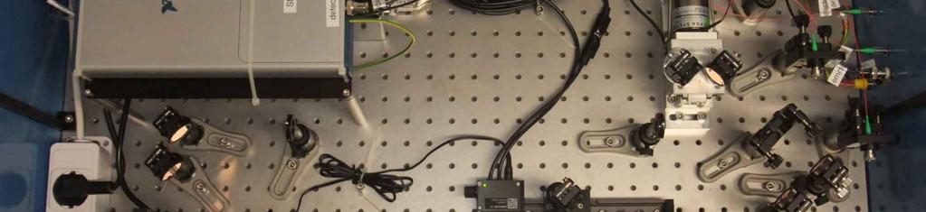
3 0. Preparation / Basics If you are using a pre-assembled THz system you will find all the components mounted to a bread board (excluding the laser that you supply yourself). This bread board needs to be fixed on an optical table using the clamps provided. The optical path was aligned using a laser with a similar wavelength as yours to make sure that the preparations done at BATOP will enable you to set up your THz spectrometer quickly. We recommend using an optical power meter as well as an IR-viewer and / or a laser viewing card in order to align the laser beam. These tools will help you to speed up the adjustment process of the optical path considerably. Warning: Since you are working with invisible short pulse laser radiation please follow all the safety measures recommended by the laser manufacturer. Any disregard may cause a serious injury to your eyes. Attention: In order to align your laser beam you will find three apertures in the THz setup that the beam has to pass through correctly (see Figure 1). These apertures will make sure that your laser beam is as collinear as possible to the one used at BATOP. This is especially important as the laser beam needs to be perfectly parallel to the movement direction of the linear stage. It is also critical that the laser beam is well collimated. Otherwise, the beam diameter will not match up with the chosen aspheric lenses mounted to the free space antennas or the collimators for the fiber-coupled antennas. If you are not sure about the divergence of your laser beam please characterize the laser beam beforehand. Figure 1: Inside of a pre-assembled THz system with apertures for laser beam alignment. Besides the optical parts you will also find power supply units for the linear stage and the data acquisition system as well as USB cables to hook up the electronics to your computer. Before connecting your equipment please read the manuals on the hardware and software carefully. In any case you have to begin with the laser beam adjustment as described in the subsequent chapters before it makes sense to work on the THz signal. 15/06/2016 3

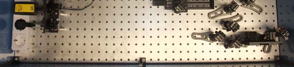
4 1. Input beam adjustment Caution: As the THz spectrometer was tested with a different laser source than yours you need to make sure that the laser beam entering the system does not damage the THz antennas. Therefore, please see the test report for the laser specifications and the measured power levels at different points in the THz system. Set your power levels accordingly in order to avoid damage to the antennas. Additionally, please note that the laser beam entering the system needs to be p-polarized. Otherwise the beam splitter and other components will not work properly. The pre-assembled THz system comes with three apertures for aligning your laser beam with the optical path of the THz spectrometer (see Figure 1). The beam height above the bread board is typically about 100 mm. As a result, you need to set the beam height of your laser beam to roughly 187 mm above your optical table (height of bread board plus feet). We suggest that you use a mirror close to the edge of the bread board in order to couple the laser beam into the THz setup. This helps you to simplify the input beam adjustment. If the system comes with housing we suggest removing the whole lid to get better access to the optical parts inside. The alignment procedure starts by threading the laser beam through all apertures using the IR viewer or the laser viewing card. Little by little reduce the aperture diameters down to their minimum and readjust the orientation of the laser beam that is fed into the setup. We suggest that you use apertures 1 & 2 as a starting point. Then you can move on to the combination of apertures 1 & 3 to get a more accurate first alignment. If you find that the laser beam is not split 1:1 at the beam splitter than you need to check the polarization of the laser beam entering the THz setup. Figure 2: Designated laser beam path with sensor for final optimization procedure. For the next step you ll need the power meter to finalize the optical alignment. In order to fine tune the laser beam path open the second aperture, reduce the aperture diameter of the first and third aperture to their minimum and try to improve the optical power behind the third aperture by altering the orientation of the laser beam entering the setup. Once the power is at a maximum your laser beam is collinear to the one used to pre-align the THz system. This step is crucial as it determines the quality of the laser beam alignment. Once you re done with the alignment procedure of the laser beam you may now open all apertures. Caution: Before you move on to optimize the illumination of the THz antennas please check the power levels before the antennas / collimators one final time and compare these values to the numbers specified in the test report. Adjust the attenuator according to the requirements if needed. 15/06/2016 4
5 2. Working with free space antennas Caution: As you provide your own laser make sure that the pulse fluence of the laser spot on the antenna gap does not exceed the specifications. As we supply the antennas with a chosen aspheric lens, the optical power needs to be adapted to the beam diameter, repetition rate and pulse duration. If you have any questions in this regard please see the test report, the spec sheets of the antennas, visit our website or contact us. After you have finished the alignment of the laser beam through the apertures you can check if the antennas are illuminated correctly by hooking them up to a multimeter (directly or via the side panel) and measure their resistance with and without illumination. You need to compare these values to the data sheet. If you find that the resistance under illumination is not as low as specified you may adjust the orientation of the last mirror before the antennas. You can use the knobs on the mounts but be careful as the antenna resistance is very sensitive to small changes in orientation. Once the resistances match the data sheet (concentrate on the ratio with and without illumination) you can connect the antennas back to the hardware and start looking for a THz signal using the T3DS software. Please follow the instructions provided in the software and hardware manuals. In general you can adjust the THz beam path as well as the optical path in order to improve the signal strength. However, since the THz path has been optimized at BATOP and you just optimized the antenna illumination we expect that only minor adjustments are needed in order to optimize the THz signal. You can have a look on the test report in order to compare your results to the reference measurement. Make sure that you use the transmission setup without focusing lenses. This is the setup that the specifications have been determined with. 15/06/2016 5


6 3. Working with fiber-coupled antennas Caution: As you provide your own laser make sure that the optical power inside the fiber does not exceed the antenna specifications before connecting them to the setup. In order to check this criterion we supply another single-mode fiber of the same type with two FC/APC connectors. Before hooking up the antennas please confirm with this optical fiber that the maximum optical power that can be coupled in matches the antenna specifications. If you have any questions in this regard please see the test report, the spec sheets of the antennas, visit our website or contact us. In case of fiber-coupled antennas there are two possibilities. For 1550 nm antennas the dispersion compensation is typically accomplished using special optical fibers attached to the THz antenna. In contrast, for 800 nm and 1000 nm antennas the dispersion compensation is accomplished using a pulse stretcher incorporating two ruled gratings for each antenna (see Figure 3). In both cases the two laser beams for the emitter and detector antenna pass a number of optical elements before they are each directed towards a separate collimator and coupled into the single mode fibers. Figure 3: Laser beam path through a pulse stretcher, based on ruled transmission gratings. After aligning the laser beam that is coupled into the system please now hook up your power meter to the optical fiber provided and attach the other end of the fiber to the side panel / connector / collimator (depending on your THz system). By adjusting the orientation of the collimator mount and the mount of the last mirror before the collimator you can now maximize the light coupled into the fiber. In case you are not able to achieve the power level specified in the test report you may also need to adjust the focus of the collimator (could be the case if your beam diameter is much different). To do so please loosen the set screw on the tip of the collimator slightly and turn the ring holding the front lens. Now, you need to optimize the power by adjusting the mirror and collimator orientation once more. If you do not get an increasing power level you have to turn the front lens into the opposite direction and repeat the procedure described. With this iterative process you should be able to get the same power level inside the fiber as specified in the test report. At the end of this process you have to fix the set screw and do one final optimization step before repeating this procedure with the second collimator. After adjusting the optical power for both collimators you can remove the optical fiber, attach the antennas to the corresponding side panel / connector / collimator and start measuring the resistances with and without illumination. If the ratio between the two resistances does not match the specifications this is an indication that the optical power on the THz antenna might not exactly be the same as in the test report. 15/06/2016 6
.")

7 If you attached the antenna fiber directly to the collimator you need to readjust the orientation of the last mirror before the collimator, the collimator itself or the focal length of the collimator. If your antenna fiber is attached to the side panel / connector you may loose some optical power due to the coupling (not uncommon for 780 nm systems because of the small mode field diameter). In this case you can adjust the attenuator slightly to increase the power level in general. However, only minor adjustments of the power level should be made as this will influence the power level for other antennas as well. Once the resistances match the data sheet (concentrate on the ratio with and without illumination) you can connect the antennas to the data acquisition unit and start looking for a THz signal using the T3DS software. Please follow the instructions provided in the software and hardware manuals. In general you can adjust the THz beam path as well as the optical path in order to improve the signal strength. However, since you already optimized the illumination of the antennas we recommend focusing on the THz beam path. Hence, you need to adjust the orientation of the antenna packages. Have a look on the test report in order to compare your results to the reference measurement. Make sure that you use the transmission setup without focusing lenses. This is the setup that the specifications have been determined with. Attention: If your THz signal is smaller and the band width narrower then specified in the test report this could be an indication that the dispersion compensation does not work as well for your laser source. The most likely reason is a difference in the wavelength between the two lasers used. A second possibility is a much shorter pulse duration / wider bandwidth of the laser leading to higher order dispersion effects. In case the results of the test report cannot be reproduced at all please get in touch with us. 15/06/2016 7
8 4. Contact details If you have any further questions or remarks, please do not hesitate to contact us. BATOP GmbH Wildenbruchstr. 15 D Jena Germany Tel.: Fax.: /06/2016 8
Kit for building your own THz Time-Domain Spectrometer
 Kit for building your own THz Time-Domain Spectrometer 16/06/2016 1 Table of contents 0. Parts for the THz Kit... 3 1. Delay line... 4 2. Pulse generator and lock-in detector... 5 3. THz antennas... 6
Data sheet for TDS 10XX system THz Time Domain Spectrometer TDS 10XX
 THz Time Domain Spectrometer TDS 10XX TDS10XX 16/02/2018 www.batop.de Page 1 of 11 Table of contents 0. The TDS10XX family... 3 1. Basic TDS system... 3 1.1 Option SHR - Sample Holder Reflection... 4 1.2
Instruction manual for T3DS software. Tool for THz Time-Domain Spectroscopy. Release 4.0
 Instruction manual for T3DS software Release 4.0 Table of contents 0. Setup... 3 1. Start-up... 5 2. Input parameters and delay line control... 6 3. Slow scan measurement... 8 4. Fast scan measurement...
FPPO 1000 Fiber Laser Pumped Optical Parametric Oscillator: FPPO 1000 Product Manual
 Fiber Laser Pumped Optical Parametric Oscillator: FPPO 1000 Product Manual 2012 858 West Park Street, Eugene, OR 97401 www.mtinstruments.com Table of Contents Specifications and Overview... 1 General Layout...
Supplementary Materials
 Supplementary Materials In the supplementary materials of this paper we discuss some practical consideration for alignment of optical components to help unexperienced users to achieve a high performance
How to align your laser for two-photon imaging
 How to align your laser for two-photon imaging Two-photon microscopy uses a laser to excite fluorescent molecules (fluorophores) within a sample through emitting short pulses of light at high power. This
EXPRIMENT 3 COUPLING FIBERS TO SEMICONDUCTOR SOURCES
 EXPRIMENT 3 COUPLING FIBERS TO SEMICONDUCTOR SOURCES OBJECTIVES In this lab, firstly you will learn to couple semiconductor sources, i.e., lightemitting diodes (LED's), to optical fibers. The coupling
CONFOCAL MICROSCOPE CM-1
 CONFOCAL MICROSCOPE CM-1 USER INSTRUCTIONS Scientific Instruments Dr. J.R. Sandercock Im Grindel 6 Phone: +41 44 776 33 66 Fax: +41 44 776 33 65 E-Mail: info@jrs-si.ch Internet: www.jrs-si.ch 1. Properties
Laser Diode Mounting Kits
 Laser Diode Mounting Kits For Ø5.6mm and Ø9mm Laser Diodes Complete Mounting System with Collimating Lens If your work involves laser diodes, you ll appreciate the benefits of Optima s laser diode mounting
SECOND HARMONIC GENERATION AND Q-SWITCHING
 SECOND HARMONIC GENERATION AND Q-SWITCHING INTRODUCTION In this experiment, the following learning subjects will be worked out: 1) Characteristics of a semiconductor diode laser. 2) Optical pumping on
3B SCIENTIFIC PHYSICS
 3B SCIENTIFIC PHYSICS Equipment Set for Wave Optics with Laser 1003053 Instruction sheet 06/18 Alf 1. Safety instructions The laser emits visible radiation at a wavelength of 635 nm with a maximum power
Devices & Services Company
 Devices & Services Company 10290 Monroe Drive, Suite 202 - Dallas, Texas 75229 USA - Tel. 214-902-8337 - Fax 214-902-8303 Web: www.devicesandservices.com Email: sales@devicesandservices.com D&S Technical
3B SCIENTIFIC PHYSICS
 3B SCIENTIFIC PHYSICS Equipment Set for Wave Optics with Laser U17303 Instruction sheet 10/08 Alf 1. Safety instructions The laser emits visible radiation at a wavelength of 635 nm with a maximum power
Instruction manual and data sheet ipca h
 1/15 instruction manual ipca-21-05-1000-800-h Instruction manual and data sheet ipca-21-05-1000-800-h Broad area interdigital photoconductive THz antenna with microlens array and hyperhemispherical silicon
Design Description Document
 UNIVERSITY OF ROCHESTER Design Description Document Flat Output Backlit Strobe Dare Bodington, Changchen Chen, Nick Cirucci Customer: Engineers: Advisor committee: Sydor Instruments Dare Bodington, Changchen
YOUNGS MODULUS BY UNIFORM & NON UNIFORM BENDING OF A BEAM
 YOUNGS MODULUS BY UNIFORM & NON UNIFORM BENDING OF A BEAM RECTANGULAR BEAM PLACED OVER TWO KNIFE EDGES & DISTANCE BETWEEN KNIFE EDGES IS KEPT CONSTANT AS l= 50cm UNIFORM WEIGHT HANGERS ARE SUSPENDED WITH
Description of options, upgrades and accessories for the laser beam stabilization system Compact
 Description of options, upgrades and accessories for the laser beam stabilization system Compact The basic configuration of the Compact laser beam stabilization system is fully equipped for stabilization
WJM Technologies excellence in material joining
 Girish P. Kelkar, Ph.D. (562) 743-7576 girish@welding-consultant.com www.welding-consultant.com Laser Focus Spot Size Control Interaction of a laser beam with any material is a function of energy density,
User s Guide Modulator Alignment Procedure
 User s Guide Modulator Alignment Procedure Models 350, 360, 370, 380, 390 series Warranty Information Conoptics, Inc. guarantees its products to be free of defects in materials and workmanship for one
ECEN. Spectroscopy. Lab 8. copy. constituents HOMEWORK PR. Figure. 1. Layout of. of the
 ECEN 4606 Lab 8 Spectroscopy SUMMARY: ROBLEM 1: Pedrotti 3 12-10. In this lab, you will design, build and test an optical spectrum analyzer and use it for both absorption and emission spectroscopy. The
Beam Shaping and Simultaneous Exposure by Diffractive Optical Element in Laser Plastic Welding
 Beam Shaping and Simultaneous Exposure by Diffractive Optical Element in Laser Plastic Welding AKL`12 9th May 2012 Dr. Daniel Vogler Page 1 Motivation: Quality and flexibility diffractive spot shaping
Guide to SPEX Optical Spectrometer
 Guide to SPEX Optical Spectrometer GENERAL DESCRIPTION A spectrometer is a device for analyzing an input light beam into its constituent wavelengths. The SPEX model 1704 spectrometer covers a range from
Application Note (A11)
") Application Note (A11) Slit and Aperture Selection in Spectroradiometry REVISION: C August 2013 Gooch & Housego 4632 36 th Street, Orlando, FL 32811 Tel: 1 407 422 3171 Fax: 1 407 648 5412 Email: sales@goochandhousego.com
Application Note (A11) Slit and Aperture Selection in Spectroradiometry REVISION: C August 2013 Gooch & Housego 4632 36 th Street, Orlando, FL 32811 Tel: 1 407 422 3171 Fax: 1 407 648 5412 Email: sales@goochandhousego.com
Week IX: INTERFEROMETER EXPERIMENTS
 Week IX: INTERFEROMETER EXPERIMENTS Notes on Adjusting the Michelson Interference Caution: Do not touch the mirrors or beam splitters they are front surface and difficult to clean without damaging them.
Table of Content. Fiber-Coupled LED s Light-Guide-Coupled LED s LED Collimator Sources Low-cost LED Spot Lights...
 LIGHT SOURCES Table of Content Fiber-Coupled s... 40 -Guide-Coupled s... 41 Collimator... 42 Low-cost Spot s... 43 Precision Spot s... 45 Spectrum Synthesizing ( Cubic S )... 46 Spectrometers 39 sources
ADVANCED OPTICS LAB -ECEN Basic Skills Lab
 ADVANCED OPTICS LAB -ECEN 5606 Basic Skills Lab Dr. Steve Cundiff and Edward McKenna, 1/15/04 Revised KW 1/15/06, 1/8/10 Revised CC and RZ 01/17/14 The goal of this lab is to provide you with practice
Spatially Resolved Backscatter Ceilometer
 Spatially Resolved Backscatter Ceilometer Design Team Hiba Fareed, Nicholas Paradiso, Evan Perillo, Michael Tahan Design Advisor Prof. Gregory Kowalski Sponsor, Spectral Sciences Inc. Steve Richstmeier,
Designing for Femtosecond Pulses
 Designing for Femtosecond Pulses White Paper PN 200-1100-00 Revision 1.1 July 2013 Calmar Laser, Inc www.calmarlaser.com Overview Calmar s femtosecond laser sources are passively mode-locked fiber lasers.
FRAUNHOFER AND FRESNEL DIFFRACTION IN ONE DIMENSION
 FRAUNHOFER AND FRESNEL DIFFRACTION IN ONE DIMENSION Revised November 15, 2017 INTRODUCTION The simplest and most commonly described examples of diffraction and interference from two-dimensional apertures
Sintec Optronics Technology Pte Ltd 10 Bukit Batok Crescent #07-02 The Spire Singapore Tel: Fax:
 Sintec Optronics Technology Pte Ltd 10 Bukit Batok Crescent #07-02 The Spire Singapore 658079 Tel: +65 63167112 Fax: +65 63167113 High-power Nd:YAG Self-floating Laser Cutting Head We supply the laser
Unit-23 Michelson Interferometer I
 Unit-23 Michelson Interferometer I Objective: Study the theory and the design of Michelson Interferometer. And use it to measure the wavelength of a light source. Apparatus: Michelson interferometer (include
APE Autocorrelator Product Family
 APE Autocorrelator Product Family APE Autocorrelators The autocorrelator product family by APE includes a variety of impressive features and properties, designed to cater for a wide range of ultrafast
pulsecheck The Modular Autocorrelator
 pulsecheck The Modular Autocorrelator Pulse Measurement Perfection with the Multitalent from APE It is good to have plenty of options at hand. Suitable for the characterization of virtually any ultrafast
Variable Anamorphic Prism Pair. Manual
 Variable Anamorphic Prism Pair Manual Article Number: APP J 390-420 APP J 600-1100 APP J 1100-1500 Manual: M-002 Version 02 Copyright 2010 TOPTICA Photonics AG Serial Number: TOPTICA Photonics AG Lochhamer
ADVANCED OPTICS LAB -ECEN 5606
 ADVANCED OPTICS LAB -ECEN 5606 Basic Skills Lab Dr. Steve Cundiff and Edward McKenna, 1/15/04 rev KW 1/15/06, 1/8/10 The goal of this lab is to provide you with practice of some of the basic skills needed
Be aware that there is no universal notation for the various quantities.
 Fourier Optics v2.4 Ray tracing is limited in its ability to describe optics because it ignores the wave properties of light. Diffraction is needed to explain image spatial resolution and contrast and
Akinori Mitani and Geoff Weiner BGGN 266 Spring 2013 Non-linear optics final report. Introduction and Background
 Akinori Mitani and Geoff Weiner BGGN 266 Spring 2013 Non-linear optics final report Introduction and Background Two-photon microscopy is a type of fluorescence microscopy using two-photon excitation. It
GWU versascan. Beta - Barium Borate. Optical Parametric Oscillator. User Manual
 GWU versascan Beta - Barium Borate Optical Parametric Oscillator User Manual V 1.63 Copyright GWU 03/2012 1 LASER SAFETY 4 1.1 Location of the safety labels 4 1.1.1 Label types English 7 1.1.2 Label types
Characteristics of point-focus Simultaneous Spatial and temporal Focusing (SSTF) as a two-photon excited fluorescence microscopy
 as a two-photon excited fluorescence microscopy") Characteristics of point-focus Simultaneous Spatial and temporal Focusing (SSTF) as a two-photon excited fluorescence microscopy Qiyuan Song (M2) and Aoi Nakamura (B4) Abstracts: We theoretically and experimentally
Characteristics of point-focus Simultaneous Spatial and temporal Focusing (SSTF) as a two-photon excited fluorescence microscopy Qiyuan Song (M2) and Aoi Nakamura (B4) Abstracts: We theoretically and experimentally
intelliweld smart welding
 intellield more Information at: smart welding Designed for robot-assisted welding applications, this 3D-scan system is capable of swiftly positioning the laser beam along 3D contours. hile a robot guides
OPERATING MANUAL. 100 MHz CENTER FREQUENCY OFF AXIS ACOUSTO-OPTIC BEAM DEFLECTOR MODEL NUMBER: DEG-.51 DOCUMENT NUMBER: 51A12229A
 OPERATING MANUAL 100 MHz CENTER FREQUENCY OFF AXIS ACOUSTO-OPTIC BEAM DEFLECTOR MODEL NUMBER: DOCUMENT NUMBER: 51A12229A Document approved for release: W Seale Date: 8/18/06 US OFFICE: NEOS Technologies,
Please let us know if you have any questions.
 Photonic Solutions PLC. Gracemount Business Pavilions, 40 Captains Road, Unit A2/A3, Edinburgh, EH17 8QF t: 0131 664 8122 f:0131 664 8144 e: sales@psplc.com w: wwwpsplc.com This Portable Document File
ADALAM Sensor based adaptive laser micromachining using ultrashort pulse lasers for zero-failure manufacturing D2.2. Ger Folkersma (Demcon)
") D2.2 Automatic adjustable reference path system Document Coordinator: Contributors: Dissemination: Keywords: Ger Folkersma (Demcon) Ger Folkersma, Kevin Voss, Marvin Klein (Demcon) Public Reference path,
D2.2 Automatic adjustable reference path system Document Coordinator: Contributors: Dissemination: Keywords: Ger Folkersma (Demcon) Ger Folkersma, Kevin Voss, Marvin Klein (Demcon) Public Reference path,
Lab 5: Brewster s Angle and Polarization. I. Brewster s angle
 Lab 5: Brewster s Angle and Polarization I. Brewster s angle CAUTION: The beam splitters are sensitive pieces of optical equipment; the oils on your fingertips if left there will degrade the coatings on
AIR-COUPLED PHOTOCONDUCTIVE ANTENNAS
 AIR-COUPLED PHOTOCONDUCTIVE ANTENNAS Report: Air-Coupled Photoconductive Antennas In this paper, we present air-coupled terahertz photoconductive antenna (THz-PCAs) transmitters and receivers made on high-resistive
Beam expansion standard concepts re-interpreted
 Beam expansion standard concepts re-interpreted Ulrike Fuchs (Ph.D.), Sven R. Kiontke asphericon GmbH Stockholmer Str. 9 07743 Jena, Germany Tel: +49-3641-3100500 Introduction Everyday work in an optics
High Energy Non - Collinear OPA
 High Energy Non - Collinear OPA Basics of Operation FEATURES Pulse Duration less than 10 fs possible High Energy (> 80 microjoule) Visible Output Wavelength Tuning Computer Controlled Tuning Range 250-375,
DESIGNING AND IMPLEMENTING AN ADAPTIVE OPTICS SYSTEM FOR THE UH HOKU KE`A OBSERVATORY ABSTRACT
 DESIGNING AND IMPLEMENTING AN ADAPTIVE OPTICS SYSTEM FOR THE UH HOKU KE`A OBSERVATORY University of Hawai`i at Hilo Alex Hedglen ABSTRACT The presented project is to implement a small adaptive optics system
Pulsed Laser Power Measurement Systems
 Pulsed Laser Power Measurement Systems Accurate, reproducible method of determining total laser and laser diode power Ideal for Beam Power Measurement Labsphere s Pulsed Laser Power Measurement Systems
Technical Specifications SECTION C
 Page 1 of 12 INSTITUTE FOR PLASMA RESEARCH Technical Specifications SECTION C Design, Fabrication, assembly, testing and supply of Filter polychromators & associated components and demonstration of performance
Optics Laboratory Spring Semester 2017 University of Portland
 Optics Laboratory Spring Semester 2017 University of Portland Laser Safety Warning: The HeNe laser can cause permanent damage to your vision. Never look directly into the laser tube or at a reflection
Instructions for the Experiment
 Instructions for the Experiment Excitonic States in Atomically Thin Semiconductors 1. Introduction Alongside with electrical measurements, optical measurements are an indispensable tool for the study of
How to Properly Select a Laser Power or Energy Sensor
 How to Properly Select a Laser Power or Energy Sensor By Dick Rieley, Sales Manager, Mid Altantic and Southeast Regions, Ophir-Spiricon LLC The selection of a sensor to accurately measure the power of
Speckle free laser projection
 Speckle free laser projection With Optotune s Laser Speckle Reducer October 2013 Dr. Selina Casutt, Application Engineer Bernstrasse 388 CH-8953 Dietikon Switzerland Phone +41 58 856 3011 www.optotune.com
Diode Pointer Quick Start Guide
 Important Note: Read all Danger, Warning, Caution terms, symbols, and instructions located in the (Safety & Hazard information) on our website. Reference the Diode Pointer Specifications located on our
Educational Spectrophotometer Accessory Kit and System OS-8537 and OS-8539
 GAIN 1 10 Instruction Manual with Experiment Guide and Teachers Notes 012-06575C *012-06575* Educational Spectrophotometer Accessory Kit and System OS-8537 and OS-8539 100 CI-6604A LIGHT SENSOR POLARIZER
CHARA AO Calibration Process
 CHARA AO Calibration Process Judit Sturmann CHARA AO Project Overview Phase I. Under way WFS on telescopes used as tip-tilt detector Phase II. Not yet funded WFS and large DM in place of M4 on telescopes
AgilOptics mirrors increase coupling efficiency into a 4 µm diameter fiber by 750%.
 Application Note AN004: Fiber Coupling Improvement Introduction AgilOptics mirrors increase coupling efficiency into a 4 µm diameter fiber by 750%. Industrial lasers used for cutting, welding, drilling,
LTE. Tester of laser range finders. Integrator Target slider. Transmitter channel. Receiver channel. Target slider Attenuator 2
 a) b) External Attenuators Transmitter LRF Receiver Transmitter channel Receiver channel Integrator Target slider Target slider Attenuator 2 Attenuator 1 Detector Light source Pulse gene rator Fiber attenuator
Keysight Technologies Optical Power Meter Head Special Calibrations. Brochure
 Keysight Technologies Optical Power Meter Head Special Calibrations Brochure Introduction The test and measurement equipment you select and maintain in your production and qualification setups is one of
7. Michelson Interferometer
 7. Michelson Interferometer In this lab we are going to observe the interference patterns produced by two spherical waves as well as by two plane waves. We will study the operation of a Michelson interferometer,
COLLIMATORS AND FOCUSERS RECEPTACLE STYLE
 COLLIMATORS AND FOCUSERS RECEPTACLE STYLE FEATURES: High power handling Rugged and compact design Low insertion loss Wide wavelength range 200-2100 nm Wide range of beam diameters GRIN, aspheric, achromatic,
Collimation Tester Instructions
 Description Use shear-plate collimation testers to examine and adjust the collimation of laser light, or to measure the wavefront curvature and divergence/convergence magnitude of large-radius optical
7 WAVEMETER PROJECT #6 MODEL OEK-100. Measure the Wavelength of An Unknown laser Using 633nm and 543 nm HeNe lasers
 7 WAVEMETER Measure the Wavelength of An Unknown laser Using 633nm and 543 nm HeNe lasers MODEL OEK-100 PROJECT #6 72 7.1 Introduction A wavemeter can be constructed with a Twyman-Green interferometer.
APPLICATION NOTE. Computer Controlled Variable Attenuator for Lasers. Technology and Applications Center Newport Corporation
 APPLICATION NOTE Computer Controlled Variable Attenuator for Lasers 31 Technology and Applications Center Newport Corporation Computer Controlled Variable Attenuator for Lasers This application note describes
Microscopy. The dichroic mirror is an important component of the fluorescent scope: it reflects blue light while transmitting green light.
 Microscopy I. Before coming to lab Read this handout and the background. II. Learning Objectives In this lab, you'll investigate the physics of microscopes. The main idea is to understand the limitations
Katarina Logg, Kristofer Bodvard, Mikael Käll. Dept. of Applied Physics. 12 September Optical Microscopy. Supervisor s signature:...
 Katarina Logg, Kristofer Bodvard, Mikael Käll Dept. of Applied Physics 12 September 2007 O1 Optical Microscopy Name:.. Date:... Supervisor s signature:... Introduction Over the past decades, the number
University of Wisconsin Chemistry 524 Spectroscopic Components *
 University of Wisconsin Chemistry 524 Spectroscopic Components * In journal articles, presentations, and textbooks, chemical instruments are often represented as block diagrams. These block diagrams highlight
JAZ-ALP Adjustable Laser Pointer Operation Manual Document Number 013-RD
 JAZ-ALP Adjustable Laser Pointer Operation Manual Document Number 013-RD000-001-02-201208 Offices: Ocean Optics, Inc. World Headquarters 830 Douglas Ave., Dunedin, FL, USA 34698 Phone 727.733.2447 Fax
NCSL International 2995 Wilderness Place, Suite 107 Boulder, Colorado Office: (303) Fax: (303)
 Fax: (303)") www.metrologycareers.com 1 Instructions for the NCSLI laser pointer interferometer Warnings and cautions The laser pointer is a class 3 laser. A person could be injured if the laser beam is pointed into
www.metrologycareers.com 1 Instructions for the NCSLI laser pointer interferometer Warnings and cautions The laser pointer is a class 3 laser. A person could be injured if the laser beam is pointed into
Illumination of Linear Variable Filters with a laser beam
 Illumination of Linear Variable Filters with a laser beam The intensity distribution in the laser beam from a super continuum light-source is assumed to be purely Gaussian. The spot size on the linear
LOS 1 LASER OPTICS SET
 LOS 1 LASER OPTICS SET Contents 1 Introduction 3 2 Light interference 5 2.1 Light interference on a thin glass plate 6 2.2 Michelson s interferometer 7 3 Light diffraction 13 3.1 Light diffraction on a
Optical Microscopy and Imaging ( Part 2 )
") 1 Optical Microscopy and Imaging ( Part 2 ) Chapter 7.1 : Semiconductor Science by Tudor E. Jenkins Saroj Kumar Patra, Department of Electronics and Telecommunication, Norwegian University of Science and
1 Optical Microscopy and Imaging ( Part 2 ) Chapter 7.1 : Semiconductor Science by Tudor E. Jenkins Saroj Kumar Patra, Department of Electronics and Telecommunication, Norwegian University of Science and
This series of lasers are available with a choice of Nd:YAG, Nd:YLF, and Nd:YVO 4. System Reliability
 Photonics Industries DS Series of UV (351/355 nm) diode pumped solid-state Q-switched lasers offer a compact, hands-free system with the long-term reliability that the manufacturing industry demands. Utilizing
Whoppshel spectroscope Assembling the instrument
 Whoppshel spectroscope Assembling the instrument Rev Date Qui 0.1 29/12/2015 F. Cochard First revision, during test with O. Garde 0.2 06/01/2016 F. Cochard Text completion. 0.3 29/02/2016 F. Cochard Add
Real-time Laser Beam Position Detector. XY-4QD User Manual
 Real-time Laser Beam Position Detector XY4QD User Manual page 1 of 7 1. Introduction The XY4QD is a 4-quadrant-diode with readout electronics and outputs for x and y position. The position of the laser
HIGH POWER COLLIMATORS AND FOCUSERS PIGTAIL STYLE
 Features HIGH POWER COLLIMATORS AND FOCUSERS PIGTAIL STYLE High power handling Rugged and compact design Low insertion loss Low backreflection Wide wavelength range Wide range of beam diameters Aspheric,
The COH24-X and COH28-X also feature a phase tunability option in order to perfectly adjust the 90 of the hybrid depending on the wavelength used.
 w w w. k y l i a. c o m i n f o @ k y l i a. c o m 90 optical hybrids COH 1 Description The COH24 is a single polarization 90 optical hybrid that enables to extract phase and amplitude from a single polarization
Assembly and Experimental Characterization of Fiber Collimators for Low Loss Coupling
 Assembly and Experimental Characterization of Fiber Collimators for Low Loss Coupling Ruby Raheem Dept. of Physics, Heriot Watt University, Edinburgh, Scotland EH14 4AS, UK ABSTRACT The repeatability of
The below identified patent application is available for licensing. Requests for information should be addressed to:
 DEPARTMENT OF THE NAVY OFFICE OF COUNSEL NAVAL UNDERSEA WARFARE CENTER DIVISION 1176 HOWELL STREET NEWPORT Rl 0841-1708 IN REPLY REFER TO Attorney Docket No. 300048 7 February 017 The below identified
LASER BEAM COLLIMATOR FOR FIBER AND DIRECT DIODE LASERS
 0 FOR FIBER AND DIRECT DIODE LASERS 1 GENERAL INFORMATION 2017 OPI Photonics S.R.L. All rights reserved. OPI Photonics S.R.L. reserves the right to make changes to this document at any time without prior
SIPS instructions for installation and use
 SIPS instructions for installation and use Introduction Thank you for purchasing the Starlight Integrated Paracorr System (referred to as SIPS hereafter), which incorporates the best focuser on the market
1/8 m GRATING MONOCHROMATOR
 1/8 m GRATING GRATING OUTPUT PORT INPUT PORT 77250 1/8 m Monochromator with 6025 Hg(Ar) Spectral Calibration Lamp. Low cost, compact size and high performance, ideal for OEM applications Very efficient
Spectrum Analyzer Compact and robust spectrometers with fully customizable range and resolution parameters, able to measure pulsed and continous
 Spectrum Analyzer Compact and robust spectrometers with fully customizable range and resolution parameters, able to measure pulsed and continous lasers. Uatched resolving power Echelle spectrometers One
PCS-150 / PCI-200 High Speed Boxcar Modules
 Becker & Hickl GmbH Kolonnenstr. 29 10829 Berlin Tel. 030 / 787 56 32 Fax. 030 / 787 57 34 email: info@becker-hickl.de http://www.becker-hickl.de PCSAPP.DOC PCS-150 / PCI-200 High Speed Boxcar Modules
Wavelength Stabilization of HPDL Array Fast-Axis Collimation Optic with integrated VHG
 Wavelength Stabilization of HPDL Array Fast-Axis Collimation Optic with integrated VHG C. Schnitzler a, S. Hambuecker a, O. Ruebenach a, V. Sinhoff a, G. Steckman b, L. West b, C. Wessling c, D. Hoffmann
Week IV: FIRST EXPERIMENTS WITH THE ADVANCED OPTICS SET
 Week IV: FIRST EXPERIMENTS WITH THE ADVANCED OPTICS SET The Advanced Optics set consists of (A) Incandescent Lamp (B) Laser (C) Optical Bench (with magnetic surface and metric scale) (D) Component Carriers
Experiment 1: Fraunhofer Diffraction of Light by a Single Slit
 Experiment 1: Fraunhofer Diffraction of Light by a Single Slit Purpose 1. To understand the theory of Fraunhofer diffraction of light at a single slit and at a circular aperture; 2. To learn how to measure
Advanced Optical Communications Prof. R. K. Shevgaonkar Department of Electrical Engineering Indian Institute of Technology, Bombay
 Advanced Optical Communications Prof. R. K. Shevgaonkar Department of Electrical Engineering Indian Institute of Technology, Bombay Lecture No. # 39 Laboratory Experiment - 1 Let us now conduct some experiments
OPERATING INSTRUCTIONS AND SYSTEM DESCRIPTION FOR THE. ISO-STIM 01D STIMULUS ISOLATION UNIT ±100 V / ±10 ma, bipolar output
 OPERATING INSTRUCTIONS AND SYSTEM DESCRIPTION FOR THE ISO-STIM 01D STIMULUS ISOLATION UNIT ±100 V / ±10 ma, bipolar output VERSION 4.0 npi 2014 npi electronic GmbH, Bauhofring 16, D-71732 Tamm, Germany
Installation of OpLevs in KAGRA - Manual -
 Installation of OpLevs in KAGRA - Manual - Simon Zeidler For the Japanese version, please see here: https://gwdoc.icrr.u-tokyo.ac.jp/cgi-bin/private/docdb/showdocument?docid=7207 In this manuscript, OpLev
z t h l g 2009 John Wiley & Sons, Inc. Published 2009 by John Wiley & Sons, Inc.
 x w z t h l g Figure 10.1 Photoconductive switch in microstrip transmission-line geometry: (a) top view; (b) side view. Adapted from [579]. Copyright 1983, IEEE. I g G t C g V g V i V r t x u V t Z 0 Z
Hubble Optics CDK 17 Collimation Instructions 03/27/2012 Hubble Optics
 Hubble Optics CDK 17 Collimation Instructions 03/27/2012 Hubble Optics 1: CDK17 Specification: System Effective Focal Length: 2894.7 mm, (this might be slightly different for different set of optics) Figure
PH 481/581 Physical Optics Winter 2014
 PH 481/581 Physical Optics Winter 2014 Laboratory #1 Week of January 13 Read: Handout (Introduction & Projects #2 & 3 from Newport Project in Optics Workbook), pp.150-170 of Optics by Hecht Do: 1. Experiment
Exp. No. 13 Measuring the runtime of light in the fiber
 Exp. No. 13 Measuring the runtime of light in the fiber Aim of Experiment The aim of experiment is measuring the runtime of light in optical fiber with length of 1 km and the refractive index of optical
880 Quantum Electronics Optional Lab Construct A Pulsed Dye Laser
 880 Quantum Electronics Optional Lab Construct A Pulsed Dye Laser The goal of this lab is to give you experience aligning a laser and getting it to lase more-or-less from scratch. There is no write-up
Horiba LabRAM ARAMIS Raman Spectrometer Revision /28/2016 Page 1 of 11. Horiba Jobin-Yvon LabRAM Aramis - Raman Spectrometer
 Page 1 of 11 Horiba Jobin-Yvon LabRAM Aramis - Raman Spectrometer The Aramis Raman system is a software selectable multi-wavelength Raman system with mapping capabilities with a 400mm monochromator and
LEP Optical pumping
 Related topics Spontaeous emission, induced emission, mean lifetime of a metastable state, relaxation, inversion, diode laser. Principle and task The visible light of a semiconductor diode laser is used
GRENOUILLE.
 GRENOUILLE Measuring ultrashort laser pulses the shortest events ever created has always been a challenge. For many years, it was possible to create ultrashort pulses, but not to measure them. Techniques
1
 High Power Isolators An optical isolator, is an optical component which allows the transmission of light in only one direction. It is typically used to prevent unwanted feedback into an optical oscillator,