THE ART OF THE IMAGE: IDENTIFICATION AND REMEDIATION OF IMAGE ARTIFACTS IN MAMMOGRAPHY
|
|
|
- Vivian Tate
- 6 years ago
- Views:
Transcription


1 THE ART OF THE IMAGE: IDENTIFICATION AND REMEDIATION OF IMAGE ARTIFACTS IN MAMMOGRAPHY William Geiser, MS DABR Senior Medical Physicist MD Anderson Cancer Center Houston, Texas
2 INTRODUCTION Screen Film Mammography Processor Related Technologist Related Equipment Related Patient Related Digital Mammography Detector Related Processing Related Equipment related Patient Related
3 LEARNING OBJECTIVES 1. Have a renewed appreciation for the variety of causes and presentation of imaging artifacts in mammography. 2. Learn techniques to assist in the investigation of imaging artifacts. 3. Discover online educational resources to continue their education on image artifact presentation and remediation.

4 THE STORY Identification of the artifact Trouble shooting Resolution if known
5 IMAGE QUALITY: WHO IS RESPONSIBLE? Technologist Film Screen Digital (FFDM, CR) Radiologist Film Screen Digital Medical Physicist Film Screen Digital
6 TECHNOLOGIST Film Screen Overall image quality check Positioning Blurring Artifacts Turn in mostly artifact free images to radiologist Digital First look Positioning Large scale and easily visible artifacts

7 FILM ON VIEW BOX

8 TECHNOLOGIST DIGITAL IMAGE DISPLAY

9 RADIOLOGIST DIGITAL DISPLAY
10 MEDICAL PHYSICIST Film Screen Annual testing Help with processor problems View boxes and viewing conditions Digital Quantification of artifacts Processing Detector related
11 BASIC FILM SCREEN ARTIFACTS Processor Technologist Mammographic Unit Patient
12 PROCESSOR RELATED ARTIFACTS Fixer Retention Scratches Static

13 This incompletely fixed film is browned.
14 FILM DISCOLORATION Film discoloration may result from incomplete or improper fixation. Loss of circulation in the fixer tank, improperly mixed fixer, a low amount of fixer, or low fixer temperature may cause incomplete or improper fixation.


15 Scratches
16 Scratches and scrapes may result from dirty or worn rollers, incorrect tension on the drive chains, improperly positioned crossover rollers, misaligned guide shoes, improper alignment of the film on the feed tray, improperly mixed processor chemicals, or a deficient replenishment rate. Wedding rings, long fingernails are also causes of film scratches.


17 Lightning-like static artifact.
18 Static artifact may result from low humidity, under-replenishment of processor chemicals, improper film handling, or improper electrical grounding of the processor. Extremely dry air in the area may also be a cause.
19 TECHNOLOGIST FILM HANDLING Improper loading Cassette cleaning Finger Prints Scratches
20 Improper loading of films or cassettes into the mammography unit is a common cause of mammographic artifacts. Accidental loading of two films into the same cassette will result in an underexposed silhouette of the breast. A film that is folded inside the cassette will have an underexposed area with a linear crease artifact and an adjacent area of poor screen-film contact.

21 This underexposed image is the result of having two films in the same cassette.
 and adjacent poor")

22 Linear crease artifact (black arrows) and adjacent poor screen-film contact (orange arrows) result from the film being folded in the cassette.

23 The internal structure of the cassette is superimposed on the image when the cassette is loaded upside-down into the Bucky tray.
 is superimposed")


24 The identification flash (arrow) is superimposed over the breast when the cassette is loaded in a front-back reversed fashion into the Bucky tray.

.")
25 Cleaning solution artifacts (arrows).

26 Fingerprints (arrows).

27 Fingerprints (short arrows) and calcifications (long arrows). Fingerprints can obscure detail when evaluating mammograms for calcifications.
28 ARTIFACTS IN DIGITAL MAMMOGRAPHY Detector based artifacts Machine based artifacts Patient related artifacts Processing and storage artifacts

29 Dead pixel group projecting over an implant.


30 The same dead pixel group seen in a standard LCC view. Individual dead pixels are mapped out by the service engineer.
31 DEAD DETECTOR ELEMENT Not necessarily clinically significant Usually identified on weekly artifact evaluation images Requires service call to get detector element mapped out
32 DETECTOR FAILURE As a detector gets damaged by exposure to radiation, pixels begin to be damaged and no longer operate properly. The following images show a detector at the end of its useful life. Note the many dead pixels and how they look like small scattered calcifications. Subsequent testing using a flat field phantom and the ACR accreditation phantom showed the damage to the detector. This detector was replaced.


33 FFDM detector failure showing large numbers of misread or dead pixels. These can look like clusters of microcalcifications


34 Flat field image of a detector as it starts to fail. Note the white band of dead pixels.

35 Magnification image of the ACR Accreditation phantom on a detector as it starts to fail. Note the white band of dead pixels. This room was taken out of service immediately and the detector replaced within a couple of days
36 DETECTOR FAILURE Many modes of failure Dead lines Inability to map out dead elements Usually requires intervention by service engineer Will require detector to be replaced


37 Failure of a line to read out during read out of the detector. System corrected itself on repeat exposure.
38 DEAD LINES OR MISREAD LINES Technologist took image and noted an artifact Continued with exam Artifact disappeared on next image Retake of same projection was satisfactory Determined that gate line did not turn on Tech support had service engineer install new sequence file for readout


39 Banding Artifact View: RCC kvp: 29 mas: 65 Compressed Thickness: 7.9 cm Compression Force: <10 lbs

40 Tire Tracks

41 Tire Tracks Caused by a shock to the detector during read out
42 BANDING ARTIFACT Cause: According to Hologic this artifact is caused by either a shock to the detector during the readout phase or a problem with a mismatch between the frequency of the power supply for the detector and the readout of the detector. The fix: if the artifact is not seen on multiple images and does not interfere with diagnosis nothing needs to be done immediately. We just watch that system more closely to see if it becomes a common occurrence. If it starts showing up more frequently say one image per day then we have the power supply for the detector replaced.
43 OTHER DETECTOR ARTIFACTS Small dark spot Determined to be from detector Cannot be calibrated out Detector was replaced


44
45 GHOST IMAGE Selenium detector technology had ghosting problems Temperature of detector plays large part Ensure that detector is at proper temperature to prevent ghosting

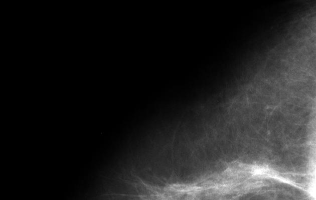
46 Ghost of the previous MLO image is visible on this RLM. This ghost image was cause by incorrect detector temperature. Allowing the detector to warm up properly cleared the problem.
47 MACHINE BASED ARTIFACTS Machine based artifacts are those artifacts that are related to components on the gantry but not part of the detector. Most of these artifacts come from dirt or dust on the compression paddle or problems with the tube filtration and the grid. With digital systems, technique can also play a role in the look of the image. The image may process well and have the correct contrast and grey scale. But improper technique may cause high noise which may obscure small objects that need to be seen.


48 RMLO Zoom RLM Zoom
49 DUST OR DIRT ON COMPRESSION PADDLE Dust or dirt on the compression paddle may mimic calcifications or masses. Look for an artifact that is seen on two different images but in the same area of the detector (flipped and rotated). Regular cleaning of compression paddles will prevent this artifact

.")
50 Gridlines on image (grid shadow) These gridlines were caused by having the grid speed set incorrectly. This caused the grid to be stopped during the exposure, leaving the grid shadow on the image (cross hatch pattern in the region of the clip marker). Required service call to have grid speed parameter reset

51 GRID ARTIFACT STUCK GRID


52 Grid Artifact Stuck Grid Replacement Detector Grid rails not affixed properly Rubbing of grid on breast support prevented grid from reciprocating Required replacement of detector array

53 Grid stuck in retracted position
54 GRID LINES Grid lines can be caused by either a stuck grid or inappropriate grid speed parameter setting. In our case this is usually visible to the radiologist. New Dimensions system service engineer had to perform grid calibration with gantry rotated 90 degrees

55 Edge of the compression paddle seen on the image. The compression paddle needed to be realigned so that its shadow was not longer visible along the chest wall edge of the image Check all paddles on during annual testing
56 TECHNIQUE PROBLEMS Clearly visible calcification seen through a hematoma on a standard LCC Noise on the LMCC image obscures the calcification. This image should be repeated at a higher kvp and with an exposure compensation of at least 2.

57 Radiologist wanted to see calcification more clearly and called for a magnification view

58 Magnification view Magnification view done, but was underexposed in the area of interest. Image noise obscures the calcification
59 UNDER EXPOSURE For immediate fix, have the technologist increase exposure compensation You can have the AEC recalibrated to give slightly higher exposures for the magnification mode as long as the system still meets the requirements for AEC tracking as required in the QC manual. Hologic made this happen in the latest Selenia software upgrade.


60 AEC failure Over Exposure View: RCC kvp: 32 mas: 215 Exposure Index: 991 Compression Thickness: 7.2 cm Compression Force: <10 lbs


61 Over Exposure - Correct Exposure View: RXCCL kvp: 30 mas: 65.9 Exposure Index: 473 Compression Thickness: 58 Compression Force: 10 lbs
62 AEC FAILURE - OVEREXPOSURE What happened Technologist had the system in Auto Filter mode which is the full automatic mode. The AEC algorithm tries to penetrate the most dense part of the breast which in this case was a large dense calcification. This lead to a very high mas and a over exposure of the skin line of the breast. Due to the high skin line exposure the processing algorithm responsible for finding the skin line and processing it failed, causing the skin line to look burned out. Note the RXCCL which was properly exposed has a good rendering of the skin line. The technologist needs to have an understanding of how the AEC system works. To prevent this problem the technologist should have reviewed the previous images and realized that she needed to manually select the AEC sensor region, placing it outside the area of the large calcification.


63 In place view underexposed View: LCC kvp: 28 mas: 65 Compressed Thickness: 11.5 cm Compression Force: < 10 lb Exposure Index: 59


64 In place view underexposed tech repeat View: LCC kvp: 30 mas: 95 Compressed Thickness: 9.8 cm Compression Force: 14.0 lb Exposure Index: 99
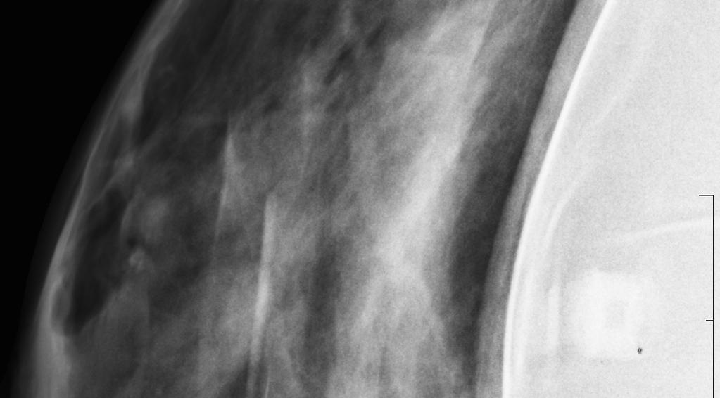
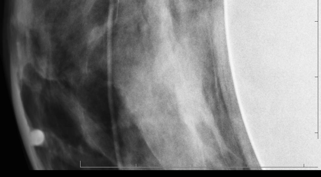
65 IN PLACE VIEW UNDEREXPOSURE What happened the technologists use a manual technique when performing in place views of the augmented breast. In the underexposed view the technologist used a technique that was not able to adequately penetrate the breast tissue around the implant. Many of the pixels were given a value of 0 and processed as completely white. On repeat of the view after call back the technologist used a higher technique and more compression. The caused all of the detector under the breast to be adequately exposed and thus process out properly
66 PATIENT RELATED ARTIFACTS There are many different types of patient related artifacts. The most common artifact is patient motion. Other types of artifacts include hair, gowns or other foreign objects laid over the breast during imaging. At other times the technologist may not notice that the patient has placed a hand on the breast support plate or compression paddle or that there are other foreign objects in the image field.


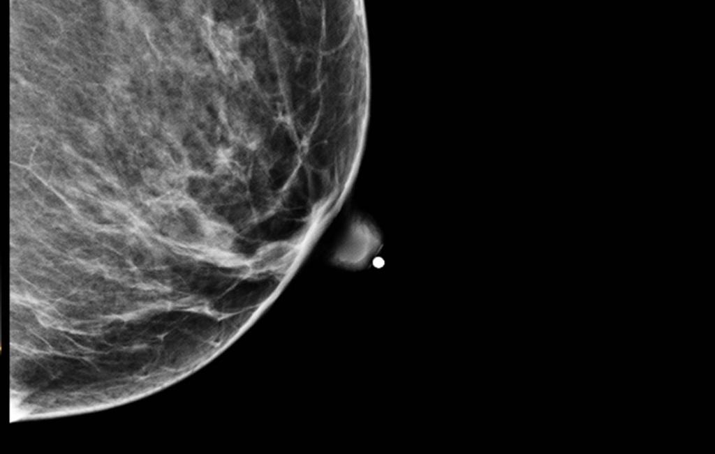
67 Blurred edge on clips Figure 10a


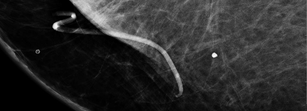
68 Sharp well defined clip edges
69 MOTION ARTIFACT Most common patient related artifact Need to have adequate compression May need to increase kvp to lower exposure time
Acceptance Testing of a Digital Breast Tomosynthesis Unit
 Acceptance Testing of a Digital Breast Tomosynthesis Unit 2012 AAPM Spring Clinical Meeting Jessica Clements, M.S., DABR Objectives Review of technology and clinical advantages Acceptance Testing Procedures
Challenges in Mammography: Part 1, Artifacts in Digital Mammography
 Integrative Imaging Pictorial Essay Geiser et al. rtifacts in Digital Mammography Integrative Imaging Pictorial Essay CME SM Challenges in Mammography Downloaded from www.ajronline.org by 148.251.232.83
MAMMOGRAPHY - HIGH LEVEL TROUBLESHOOTING
 MAMMOGRAPHY - HIGH LEVEL TROUBLESHOOTING Maynard High New York Medical College SS2001-M.High 1 Objectives: Review MQSA and ACR annual QC tests as opportunities for troubleshooting before a significant
Multiple Choice Identify the letter of the choice that best completes the statement or answers the question.
 RA202 image production class two Multiple Choice Identify the letter of the choice that best completes the statement or answers the question. 1. What removes excess chemistry from the film prior to it
Quality Control for Stereotactic Breast Biopsy. Robert J. Pizzutiello, Jr., F.A.C.M.P. Upstate Medical Physics, Inc
 Quality Control for Stereotactic Breast Biopsy Robert J. Pizzutiello, Jr., F.A.C.M.P. Upstate Medical Physics, Inc. 716-924-0350 Methods of Imaging Guided Breast Biopsy Ultrasound guided, hand-held needle
DIGITAL RADIOGRAPHY ARTIFACTS
 IMAGING LAB MPHY 487 DIGITAL RADIOGRAPHY ARTIFACTS Mohammad Esmael Alsulimane B.Sc, M.Sc Medical Physics Lecturer - Physics Department All Rights Reserved: Some information and figures in this presentation
Mammography is a radiographic procedure specially designed for detecting breast pathology Approximately 1 woman in 8 will develop breast cancer over
 Mammography is a radiographic procedure specially designed for detecting breast pathology Approximately 1 woman in 8 will develop breast cancer over a lifetime Breast cancer screening programs rely on
Practical Aspects of Medical Physics Surveys of Mammography Equipment and Facilities
 Practical Aspects of Medical Physics Surveys of Mammography Equipment and Facilities Melissa Martin, M.S., FAAPM, FACR, FACMP AAPM Annual Meeting - Philadelphia July 19, 2010 MO-B-204C-1 Educational Objectives
7/20/2014. Outline. Outline. Disclosures. Learning Objectives. SBB: Practical Aspects of ACR Accreditation, QC and ACR On Site Surveys
 Outline SBB: Practical Aspects of ACR Accreditation, QC and ACR On Site Surveys Robert J. Pizzutiello, MS, FACR, FAAPM, FAC Residency Program Director, Upstate Medical Physics, PC Senior Vice President,
COMPUTED RADIOGRAPHY CHAPTER 4 EFFECTIVE USE OF CR
 This presentation is a professional collaboration of development time prepared by: Rex Christensen Terri Jurkiewicz and Diane Kawamura New Technology https://www.youtube.com/watch?v=ptkzznazb 7U COMPUTED
1.1.Clinical Artefacts
 1.1.Clinical Artefacts While the incidence of artefact on digital mammographic images 1 is typically less than with film based mammography, artefacts can be produced on digital systems. This section provides
Collimation Assessment Using GAFCHROMIC XR-M2
 Collimation Assessment Using GAFCHROMIC XR-M2 I. Introduction A method of collimation assessment for GE Senographe full-field digital mammography (FFDM) systems is described that uses a self-developing
Breast Tomosynthesis. Bob Liu, Ph.D. Department of Radiology Massachusetts General Hospital And Harvard Medical School
 Breast Tomosynthesis Bob Liu, Ph.D. Department of Radiology Massachusetts General Hospital And Harvard Medical School Outline Physics aspects of breast tomosynthesis Quality control of breast tomosynthesis
Digital Imaging started in the 1972 with Digital subtraction angiography Clinical digital imaging was employed from the 1980 ~ 37 years ago Amount of
 Digital Imaging started in the 1972 with Digital subtraction angiography Clinical digital imaging was employed from the 1980 ~ 37 years ago Amount of radiation to the population due to Medical Imaging
Image Quality. HTC Grid High Transmission Cellular Grid provides higher contrast images
 B R E A S T I M A G I N G S O L U T I O N S Setting the benchmark for mammography M-IV Series Innovations in breast imaging The Lorad M-IV Series exemplifies Hologic's commitment to developing advanced
4/19/2016. Quality Control Activities for the RadiologicTechnologist. Objectives. 3D Tomosynthesis QC differences
 Quality Control Activities for the RadiologicTechnologist Quality Control Tests 2D QC Tomosynthesis QC DICOM Printer Quality Control Weekly Detector Flat Field Calibration Weekl Artifact Evaluation Weekly
Digital radiography (DR) post processing techniques for pediatric radiology
 post processing techniques for pediatric radiology") Digital radiography (DR) post processing techniques for pediatric radiology St Jude Children s Research Hospital Samuel Brady, MS PhD DABR samuel.brady@stjude.org Purpose Review common issues and solutions
Digital radiography (DR) post processing techniques for pediatric radiology St Jude Children s Research Hospital Samuel Brady, MS PhD DABR samuel.brady@stjude.org Purpose Review common issues and solutions
GE Healthcare. Performa. High-performance breast imaging
 GE Healthcare Performa High-performance breast imaging Moving mammography forward. And patients faster. GE Healthcare s unparalleled leadership across mammography begins with a deep understanding of breast
Digital radiography: Practical advantages of Digital Radiography. Practical Advantages in image quality
 Digital radiography: Digital radiography is set to become the most common form of processing radiographic images in the next 10 years. This is due to a number of practical and image quality issues. Practical
Image Quality. HTC Grid High Transmission Cellular Grid provides higher contrast images
 B R E A S T I M A G I N G S O L U T I O N S Setting the benchmark for mammography M-IV Series Innovations in breast imaging The Lorad M-IV Series exemplifies Hologic s commitment to developing advanced
Digital Breast Tomosynthesis
 Digital Breast Tomosynthesis OLIVE PEART MS, RT(R) (M) HTTP://WWW.OPEART.COM 2D Mammography Not 100% effective Limited by tissue superimposition Overlapping tissue can mask tumors False negative Overlapping
Tomosynthesis and Motion
 Tomosynthesis (3D) Motion Unsharpness Occurs at about the same frequency as conventional mammography (2D) Presents the same issues as 2D motion, EXCEPT that motion may go undetected Most common patient-related
Mammography: Physics of Imaging
 Mammography: Physics of Imaging Robert G. Gould, Sc.D. Professor and Vice Chair Department of Radiology and Biomedical Imaging University of California San Francisco, California Mammographic Imaging: Uniqueness
KODAK DIRECTVIEW CR Mammography Feature User s Guide
 KODAK DIRECTVIEW CR Mammography Feature User s Guide 17 September 2010 9G3741 Version 1.0 Carestream Health, Inc. 150 Verona Street Rochester, NY 14608 CARESTREAM, DIRECTVIEW, and DRYVIEW are trademarks
Nuclear Associates
 Nuclear Associates 07-647 R/F QC Phantom Operators Manual March 2005 Manual No. 07-647-1 Rev. 2 2004, 2005 Fluke Corporation, All rights reserved. All product names are trademarks of their respective companies
Overview of Safety Code 35
 Common Quality Control Procedures for All s Quality Control Procedures Film All s Daily Quality Control Tests Equipment Warm-up (D1) According to manufacturers instructions Can include auto calibration(d1)
Artifacts in mammography: ways to identify and overcome them
 P i c t o r i a l E s s a y Singapore Med Med J 2006; J 2006; 47(7) 47(7) : 634 : 1 Artifacts in mammography: ways to identify and overcome them Chaloeykitti L, Muttarak M, Ng K H ABSTRACT High-quality
Introduction. Digital Mammography QA: Comparing the Manufacturers Recommendations. What is QC and why is it important? Review & compare QC tests
 Slide 1 Digital Mammography QA: Comparing the Manufacturers Recommendations Eric A. Berns, Ph.D. Slide 2 Introduction What is QC and why is it important? Review & compare QC tests Key take home points
Mammography Solution. AMULET Innovality. The new leader in the AMULET series. Tomosynthesis, 3D mammography and biopsy are all available.
 Mammography Solution AMULET Innovality The new leader in the AMULET series. Tomosynthesis, 3D mammography and biopsy are all available. FUJIFILM supports the Pink Ribbon Campaign for early detection of
Quality Control of Full Field Digital Mammography Units
 Quality Control of Full Field Digital Mammography Units Melissa C. Martin, M.S., FACMP, FACR, FAAPM Melissa@TherapyPhysics.com 310-612-8127 ACMP Annual Meeting Virginia Beach, VA May 2, 2009 History of
STEREOTACTIC BREAST BIOPSY EQUIPMENT SURVEYS
 STEREOTACTIC BREAST BIOPSY EQUIPMENT SURVEYS JAMES A. TOMLINSON, M.S. Diagnostic Radiological Physicist American Board of Radiology Certified Medical Physics Consultants, Inc. Bio 28 yrs experience 100%
Breast Imaging Basics: Module 3 Producing Quality Images
 Module 3 Transcript For educational and institutional use. This test bank is licensed for noncommercial, educational inhouse or online educational course use only in educational and corporate institutions.
Surveying and QC of Stereotactic Breast Biopsy Units for ACR Accreditation
 Surveying and QC of Stereotactic Breast Biopsy Units for ACR Accreditation AAPM Annual Clinical Meeting Indianapolis, IN August 5, 2013 Learning Objectives Become familiar with the recommendations and
Breast Imaging Basics: Module 10 Digital Mammography
 Module 10 Transcript For educational and institutional use. This test bank is licensed for noncommercial, educational inhouse or online educational course use only in educational and corporate institutions.
LECTURE 1 The Radiographic Image
 LECTURE 1 The Radiographic Image Prepared by:- KAMARUL AMIN ABDULLAH @ ABU BAKAR UiTM Faculty of Health Sciences Medical Imaging Department 11/23/2011 KAMARUL AMIN (C) 1 Lesson Objectives At the end of
GE Healthcare. Senographe 2000D Full-field digital mammography system
 GE Healthcare Senographe 2000D Full-field digital mammography system Digital has arrived. The Senographe 2000D Full-Field Digital Mammography (FFDM) system gives you a unique competitive advantage. That
Investigation of the line-pair pattern method for evaluating mammographic focal spot performance
 Investigation of the line-pair pattern method for evaluating mammographic focal spot performance Mitchell M. Goodsitt, a) Heang-Ping Chan, and Bob Liu Department of Radiology, University of Michigan, Ann
Exposure Indices and Target Values in Radiography: What Are They and How Can You Use Them?
 Exposure Indices and Target Values in Radiography: What Are They and How Can You Use Them? Definition and Validation of Exposure Indices Ingrid Reiser, PhD DABR Department of Radiology University of Chicago
4.0 How to Turn On the Selenia Dimensions
 Chapter 2 System Controls and Indicators How to Turn On the Selenia Dimensions 4.0 How to Turn On the Selenia Dimensions 4.1 Preparation 1. Reset all three Emergency Off switches. Emergency Off Switches
GE Healthcare. Essential for life. Senographe Essential Full-Field Digital Mammography system
 GE Healthcare Essential for life Senographe Essential Full-Field Digital Mammography system Excellence in FFDM is a process. An ongoing quest, fueled by our continuing breakthroughs in breast cancer detection
Performance and care. all in one
 Performance and care all in one INNOVATION IS WHAT DRIVES US THINKING ABOUT THE FUTURE Preventive diagnostics remains an essential weapon in defeating breast cancer. Metaltronica s forward-thinking design
TESTING FLAT-PANEL IMAGING SYSTEMS: What the Medical Physicist Needs to Know. JAMES A. TOMLINSON, M.S., D.A.B.R. Diagnostic Radiological Physicist
 TESTING FLAT-PANEL IMAGING SYSTEMS: What the Medical Physicist Needs to Know JAMES A. TOMLINSON, M.S., D.A.B.R. Diagnostic Radiological Physicist Topics Image Uniformity and Artifacts Image Quality - Detail
2 nd generation TOMOSYNTHESIS
 2 nd generation TOMOSYNTHESIS 2 nd generation DBT true innovation in breast imaging synthesis graphy Combo mode Stereotactic Biopsy Works in progress: Advanced Technology, simplicity and ergonomics Raffaello
Learning Objectives: What s my motivation? (unknown screen actor) Workshop Overview
 Workshop Overview") Practical Medical Physics Adapting Traditional Clinical Medical Physics to Digital Radiography Charles E. Willis, Ph.D., DABR Associate Professor Department of Imaging Physics The University of Texas M.D.
Practical Medical Physics Adapting Traditional Clinical Medical Physics to Digital Radiography Charles E. Willis, Ph.D., DABR Associate Professor Department of Imaging Physics The University of Texas M.D.
Multiple Choice Identify the letter of the choice that best completes the statement or answers the question.
 RA110 test 3 Multiple Choice Identify the letter of the choice that best completes the statement or answers the question. 1. An object 35 cm in width is radiographed at 100 cm SID and at a 50 cm SOD. What
Digital Mammography Quality Control for the Mammographic Technologist
 Ontario Breast Screening Program Digital Mammography Quality Control for the Mammographic Technologist Authors: G.E. Mawdsley, A.K. Bloomquist, M.J. Yaffe October 2011 Revision 3.1 Mammographic Physics
Maximizing clinical outcomes
 Maximizing clinical outcomes Digital Tomosynthesis Dual Energy Subtraction Automated Long Length Imaging Improved image quality at a low dose Xray Xray Patented ISS capture technology promotes high sensitivity
Digital Mammography Quality Control for the Mammographic Physicist
 Ontario Breast Screening Program Digital Mammography Quality Control for the Mammographic Physicist Authors: G.E. Mawdsley, A.K. Bloomquist, M.J. Yaffe March 2014 Revision 3.2 Mammographic Physics Consulting
History of digital imaging
 CR/QA RADCHEX History of digital imaging Early, crude digital detectors were developed in the 1970 s Image quality was problematic Processing time of digital images was untenable Viewing, transfer and
Patient-Assisted Compression Impact on Image Quality and Workflow
 Patient-Assisted Compression Impact on Image Quality and Workflow Senographe Pristina In 2017, GE Healthcare s Senographe Pristina ( Pristina ) was approved by the FDA using the standard technologist-controlled
RAD 150 RADIOLOGIC EXPOSURE TECHNIQUE II
 RAD 150 RADIOLOGIC EXPOSURE TECHNIQUE II APPROVED 12/O2/2011 EFFECTIVE SPRING 2013-14 Prefix & Number RAD 150 Course Title: Radiologic Exposure Technique II & Lab Purpose of this submission: New Change/Updated
Ludlum Medical Physics
 Ludlum Medical Physics Medical Imaging Radiology QA Test Tools NEW LUDLUM PRODUCT LINE Medical Physics Products Medical Physics Products What are they? Products used to measure radiation output and to
8/2/2017. Radiologist Responsibilities. Radiologist Responsibilities. Medical Physicist Mammography Equipment Evaluation and Annual Survey
 Implementation of the 2016 ACR Digital Mammography QC Manual Medical Physicist Mammography Equipment Evaluation and Annual Survey Eric A Berns, PhD, FACR Radiologist Responsibilities Radiologist Responsibilities
Image Display and Perception
 Image Display and Perception J. Anthony Seibert, Ph.D. Department of Radiology UC Davis Medical Center Sacramento, California, USA Image acquisition, display, & interpretation X-rays kvp mas Tube filtration
3/31/2011. Objectives. Emory University. Historical Development. Historical Development. Historical Development
 Teaching Radiographic Technique in a Digital Imaging Paradigm Objectives 1. Discuss the historical development of digital imaging. Dawn Couch Moore, M.M.Sc., RT(R) Assistant Professor and Director Emory
Essentials of Digital Imaging
 Essentials of Digital Imaging Module 4 Transcript 2016 ASRT. All rights reserved. Essentials of Digital Imaging Module 4 Image Analysis 1. ASRT Animation 2. Welcome Welcome to Essentials of Digital Imaging:
PRACTICE GUIDELINE FOR DETERMINANTS OF IMAGE QUALITY IN DIGITAL MAMMOGRAPHY
 The American College of Radiology, with more than 30,000 members, is the principal organization of radiologists, radiation oncologists, and clinical medical physicists in the United States. The College
SECTION I - CHAPTER 1 DIGITAL RADIOGRAPHY: AN OVERVIEW OF THE TEXT. Exam Content Specifications 8/22/2012 RADT 3463 COMPUTERIZED IMAGING
 RADT 3463 - COMPUTERIZED IMAGING Section I: Chapter 1 RADT 3463 Computerized Imaging 1 SECTION I - CHAPTER 1 DIGITAL RADIOGRAPHY: AN OVERVIEW OF THE TEXT RADT 3463 COMPUTERIZED IMAGING Section I: Chapter
Do you have any other questions? Please call us at (Toll Free) or , or
 or , or") INSTRUCTIONS Read the appropriate course/ textbook. This is an open book test. A score of 75% or higher is needed to receive CE credit. You will have a maximum of three attempts to pass this course. Please
INSTRUCTIONS Read the appropriate course/ textbook. This is an open book test. A score of 75% or higher is needed to receive CE credit. You will have a maximum of three attempts to pass this course. Please
ADVANCED MEDICAL SYSTEMS PTE LTD Singapore Malaysia India Australia
 Innovative design is combined with cutting-edge technology to yield a definitive diagnosis and never before seen ergonomics GIOTTO CLASS is the result of 25 years of experience in the research and development
diagnostic examination
 RADIOLOGICAL PHYSICS 2011 Raphex diagnostic examination Adel A. Mustafa, Ph.D., Editor PUBLISHED FOR: RAMPS (Radiological and Medical Physics Society of New York) preface The RAPHEX Diagnostic exam 2011
RADIOGRAPHIC EXPOSURE
 RADIOGRAPHIC EXPOSURE Receptor Exposure Receptor Exposure the that interacts with the receptor. Computed Radiography ( ) requires a. Direct Digital Radiography (DR) requires a. Exposure Indicators Exposure
MILADY. Product Data. Page 1 of 8
 Page 1 of 8 The MILADY Mammographic Unit offers the best quality-to-price ratio to our customers worldwide. The unit advanced technology together with the application of industrial production standards,
Photomultiplier Tube
 Nuclear Medicine Uses a device known as a Gamma Camera. Also known as a Scintillation or Anger Camera. Detects the release of gamma rays from Radionuclide. The radionuclide can be injected, inhaled or
TECHNICAL DATA. GIOTTO IMAGE SDL/W is pre-arranged for Full Field Digital Biopsy examination with the patient in prone position.
 Ver. 01/06/07 TECHNICAL DATA GIOTTO IMAGE SDL/W LOW DOSE, FULL FIELD DIGITAL MAMMOGRAPHY UNIT USING AMORPHOUS SELENIUM (a-se) TECHNOLOGY DETECTOR (pre-arranged for stereotactic biopsy with the same digital
Imaging Technique Optimization of Tungsten Anode FFDM System
 Imaging Technique Optimization of Tungsten Anode FFDM System Biao Chen a*, Andrew P. Smith b, Zhenxue Jing a, Elena Ingal a a Hologic, Inc. 600 Technology Drive, DE 1970 b Hologic, Inc. 35 Crosby Drive,
New spectral benefi ts, proven low dose
 New spectral benefi ts, proven low dose Philips MicroDose mammography SI, technical data sheet Philips MicroDose SI with single-shot spectral imaging is a fullfi eld digital mammography solution that delivers
QC Testing for Computed Tomography (CT) Scanner
 Scanner") QC Testing for Computed Tomography (CT) Scanner QA - Quality Assurance All planned and systematic actions needed to provide confidence on a structure, system or component. all-encompassing program, including
QC Testing for Computed Tomography (CT) Scanner QA - Quality Assurance All planned and systematic actions needed to provide confidence on a structure, system or component. all-encompassing program, including
A Practical Overview of the Clinical and Operational Impact of Computed Radiography(CR) Implementations. Shirley Weddle, RT(R)(M), CIIP, BBA
 Implementations. Shirley Weddle, RT(R)(M), CIIP, BBA") A Practical Overview of the Clinical and Operational Impact of Computed Radiography(CR) Implementations Shirley Weddle, RT(R)(M), CIIP, BBA OBJECTIVES Define Computed Radiography (CR) Discuss CR vendor
A Practical Overview of the Clinical and Operational Impact of Computed Radiography(CR) Implementations Shirley Weddle, RT(R)(M), CIIP, BBA OBJECTIVES Define Computed Radiography (CR) Discuss CR vendor
Outline. Digital Radiography. Understanding Digital Modalities: Image Quality and Dose. Image Quality. Dose Control
 Understanding Digital Modalities: Image Quality and Dose S. Jeff Shepard, M.S. University of Texas M. D. Anderson Cancer Center Houston, Texas Special Acknowledgement: Stephen K. Thompson, M.S. William
DISC QC/QA Program for Digital Imaging Systems using the DR Radchex Plus Meter
 DISC QC/QA Program for Digital Imaging Systems using the DR Radchex Plus Meter Revision Date: January 5th, 2017 www.disc-imaging.com Table of Contents Section A: Preliminary Setup Requirements... 4 Tools
Teaching Digital Radiography and Fluoroscopic Radiation Protection
 Teaching Digital Radiography and Fluoroscopic Radiation Protection WCEC 20 th Student Educator Radiographer Conference Dennis Bowman, RT(R), CRT (R)(F) Community Hospital of the Monterey Peninsula (CHOMP)
KODAK MIN-R S Film / 4906
 TECHNICAL INFORMATION DATA SHEET Copyright, Eastman Kodak Company, 2002 KODAK MIN-R S Film / 4906 1) Description KODAK MIN-R S Film / 4906 is a medium speed, dual coated, ortho-sensitive medical x-ray
Slide 1. Slide 2. Slide 3 ACR CT Accreditation. Multi-Slice CT Artifacts and Quality Control. What are the rules or recommendations for CT QC?
 Slide 1 Multi-Slice CT Artifacts and Quality Control Dianna Cody, Ph.D. Chief, Radiologic Physics UT MD Anderson Cancer Center Houston, TX Slide 2 What are the rules or recommendations for CT QC? AAPM
NJDEP Medical Physicist s Radiographic QC Survey Registration Number:
 Facility Name NJDEP ID # NJDEP Medical Physicist s Radiographic QC Survey PLEASE PRINT Facility Information Unit Information Manufacturer Model Console Model # Console serial # Tube serial # Location (room)
X-ray Imaging. PHYS Lecture. Carlos Vinhais. Departamento de Física Instituto Superior de Engenharia do Porto
 X-ray Imaging PHYS Lecture Carlos Vinhais Departamento de Física Instituto Superior de Engenharia do Porto cav@isep.ipp.pt Overview Projection Radiography Anode Angle Focal Spot Magnification Blurring
Fabrício Sampaio Péres Kury Federal University of Rio de Janeiro Medical School
 Fabrício Sampaio Péres Kury Federal University of Rio de Janeiro Medical School Harvard Medical School Exchange Clerkship Program Primary Care Radiology Clerkship Gillian Lieberman, M. D. Monday, September
Y11-DR Digital Radiography (DR) Image Quality
 Image Quality") Y11-DR Digital Radiography (DR) Image Quality Image quality is stressed for all systems in Safety Code 35. In the relevant sections Health Canada s advice is the manufacturer s recommended test procedures
Y11-DR Digital Radiography (DR) Image Quality Image quality is stressed for all systems in Safety Code 35. In the relevant sections Health Canada s advice is the manufacturer s recommended test procedures
Optimization of Digital Mammography Resolution Using Magnification Technique in Computed Radiography 1
 Optimization of Digital Mammography Resolution Using Magnification Technique in Computed Radiography 1 Gham Hur, M.D., Yoon Joon Hwang, M.D., Soon Joo Cha, M.D., Su Young Kim, M.D., Yong Hoon Kim, M.D.
ACPSEM Position Paper RECOMMENDATIONS FOR A DIGITAL MAMMOGRAPHY QUALITY ASSURANCE PROGRAM V4.0
 Heggie et al ACPSEM Position Paper: Digital Mammography V4.0 ACPSEM Position Paper RECOMMENDATIONS FOR A DIGITAL MAMMOGRAPHY QUALITY ASSURANCE PROGRAM V4.0 JCP Heggie 1, P Barnes 2, L Cartwright 3, J Diffey
Artefacts found in computed radiography
 The British Journal of Radiology, 74 (2001), 195 202 E 2001 The British Institute of Radiology Pictorial review Artefacts found in computed radiography L J CESAR, RT(R)(QM), B A SCHUELER, PhD, F E ZINK,
FFDM in the Field: Physicist's Role in the QC of Mammography Laser Printers May Carl R. Keener, Ph.D., DABMP, DABR
 FFDM in the Field: Physicist's Role in the QC of Mammography Laser Printers May 2010 Carl R. Keener, Ph.D., DABMP, DABR keener@marpinc.com MARP Medical & Radiation Physics, Inc. Physicist's Role in the
Nuclear Associates
 Nuclear Associates 07-644 Grid Alignment Test Tool Users Manual March 2005 Manual No. 07-644-1 Rev. 2 2004, 2005 Fluke Corporation, All rights reserved. Printed in U.S.A. All product names are trademarks
CR Basics and FAQ. Overview. Historical Perspective
 Page: 1 of 6 CR Basics and FAQ Overview Computed Radiography is a term used to describe a system that electronically records a radiographic image. Computed Radiographic systems use unique image receptors
GE Healthcare. Senographe Crystal The choice is crystal clear
 Senographe Crystal The choice is crystal clear Senographe Crystal The choice is crystal clear. The Senographe* Crystal mammography system makes it easy to transition to full-field digital mammography.
Exposure System Selection
 Principles of Imaging Science II (RAD120) Exposure Systems Exposure System Selection Radiographic exposure is a very complex process Best technique systems manipulate one variable while holding others
Features and Weaknesses of Phantoms for CR/DR System Testing
 Physics testing of image detectors Parameters to test Features and Weaknesses of Phantoms for CR/DR System Testing Spatial resolution Contrast resolution Uniformity/geometric distortion Dose response/signal
Overview. Professor Roentgen was a Physicist!!! The Physics of Radiation Oncology X-ray Imaging
 The Physics of Radiation Oncology X-ray Imaging Charles E. Willis, Ph.D. DABR Associate Professor Department of Imaging Physics The University of Texas M.D. Anderson Cancer Center Houston, Texas Overview
CONTRASTING VIEWS DIGITAL VS CONVENTIONAL RADIOGRAPHY
 Vet Times The website for the veterinary profession https://www.vettimes.co.uk CONTRASTING VIEWS DIGITAL VS CONVENTIONAL RADIOGRAPHY Author : PETRA AGTHE Categories : Vets Date : April 7, 2008 PETRA AGTHE
Nuclear Associates
 Nuclear Associates 07-649 CDRH Fluoroscopic Phantom Users Manual March 2005 Manual No. 07-649-1 Rev. 2 2004, 2005 Fluke Corporation, All rights reserved. Printed in U.S.A. All product names are trademarks
Compliance Guidance for RADIOGRAPHIC QUALITY CONTROL (5 th Edition)
") Compliance Guidance for RADIOGRAPHIC QUALITY CONTROL (5 th Edition) New Jersey Department of Environmental Protection Bureau of X-ray Compliance PO Box 420 Mail Code 25-01 Trenton, NJ 08625-0420 FAX 609-984-5811
Compliance Guidance for RADIOGRAPHIC QUALITY CONTROL (5 th Edition) New Jersey Department of Environmental Protection Bureau of X-ray Compliance PO Box 420 Mail Code 25-01 Trenton, NJ 08625-0420 FAX 609-984-5811
Revosoft Operators Manual
 1 Revosoft Operators Manual Contents LAUNCHING REVOSOFT:... 2 Entering a New Patient:... 2 IMAGE VIEWER:... 6 Mouse Functions:... 6 Panning the image:... 6 Magnification:... 6 Annotations:... 7 Text and
Photographic Standards in Plastic Surgery
 Photographic Standards in Plastic Surgery The standard photographic views illustrated in this card were established by the Educational Technologies Committee of the Plastic Surgery Foundation. We feel
FMT18 FLOOR MOUNTED SYSTEM
 mas Time AEC 320 kvp 64 mas 320 ma 320 ma 320 DEN 0.0 mm Cu 17 in X 17 in 72.0 in FMT18 FLOOR MOUNTED SYSTEM with Synchronized Tracking System Overview Clinical Efficiency The FMT18 System was designed
How to Print: Making an Enlargement from a Negative in the Darkroom
 How to Print: Making an Enlargement from a Negative in the Darkroom The Steps Prepare and gather all the materials and resources needed for you to work in the darkroom: Negative Storage Folder or Box Darkroom
Beam-Restricting Devices
 Beam-Restricting Devices Three factors contribute to an increase in scatter radiation: Increased kvp Increased Field Size Increased Patient or Body Part Size. X-ray Interactions a some interact with the
Understanding Quantra 2.0 User Manual
 BREAST IMAGING SOLUTIONS Understanding Quantra 2.0 User Manual MAN-02004 Rev 004 Understanding Quantra 2.0 User Manual MAN-02004 Rev 004 Technical Support For support in North America contact: Toll Free:
Aspire HD. Program Manual. 2nd Edition - October 2012
 Quality Control 1 Aspire HD Quality Control Program Manual 2nd Edition - October 2012 Overview Installation of FDR Mammography QC Program Weekly Test 2 3 4 Quarterly Test 5 Semi-annual Test 6 Annual Test
X-RAY IMAGING EE 472 F2017. Prof. Yasser Mostafa Kadah
 X-RAY IMAGING EE 472 F2017 Prof. Yasser Mostafa Kadah www.k-space.org Recommended Textbook Stewart C. Bushong, Radiologic Science for Technologists: Physics, Biology, and Protection, 10 th ed., Mosby,
GE Healthcare. Senographe Crystal The choice is crystal clear
 Senographe Crystal The choice is crystal clear Senographe Crystal The choice is crystal clear. The Senographe* Crystal mammography system makes it easy to transition to full-field digital mammography.