STEREOTACTIC BREAST BIOPSY EQUIPMENT SURVEYS
|
|
|
- Christina McDaniel
- 5 years ago
- Views:
Transcription
1 STEREOTACTIC BREAST BIOPSY EQUIPMENT SURVEYS JAMES A. TOMLINSON, M.S. Diagnostic Radiological Physicist American Board of Radiology Certified Medical Physics Consultants, Inc.
2 Bio 28 yrs experience 100% Dx Rad >100 mammo systems/yr 15 are dedicated stereotactic units
3 SBB-Testing Requirements Currently exempt from MQSA certification and ACR accreditation (voluntary). Some states require testing, all tests that are applicable. This focus is on dedicated units with digital IR.

4 Testing Procedures The ACR-SBB manual contains testing procedures for technologists and physicists. There are options for filmscreen units and those with digital receptors.
5 SBB Units Dedicated prone table units are made by Fischer and Lorad. Other re-salers have put their label on the Lorad unit. Add-on stereotactic devices are also used. We will only discuss the prone table units.

6 FISCHER MAMMOTEST

7 Multi-Angle Biopsy
8 Image Receptor 9-10 lp/mm Min-R screen 5x5cm Fiber-optic taper CCD 1 x1 1024x1024
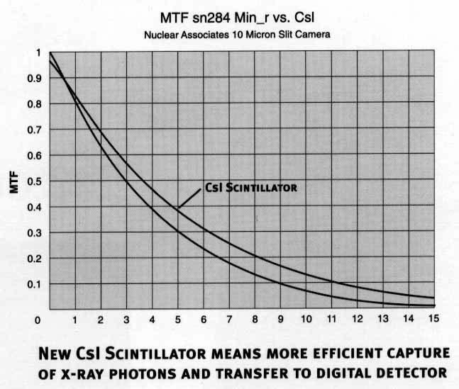
9 MTF
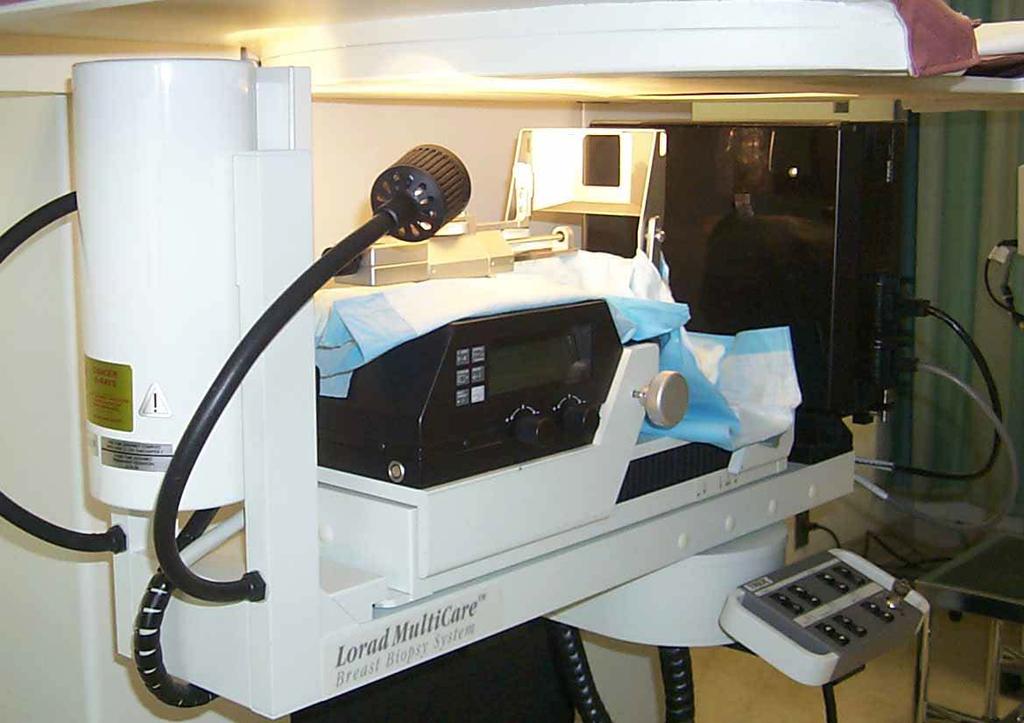
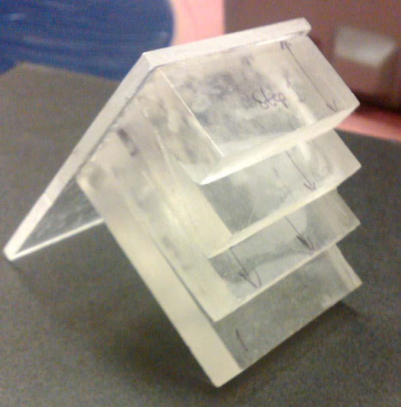
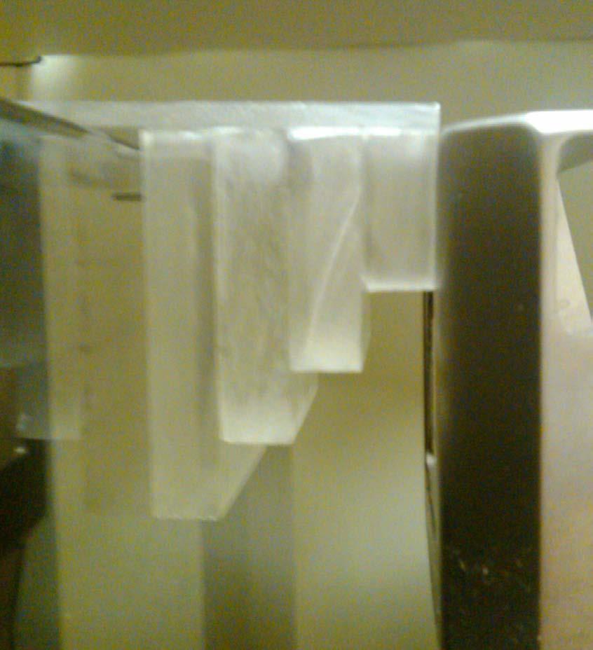
10 LORAD STEREOGUIDE

11 Breast support Detector assembly
12 Image Receptor ~5 lp/mm lp/mm Lens Mirror CCD 1 x1 1024x1024 Lanex screen
13 EQUIPMENT TESTING 1. Unit assembly evaluation 2. Collimation assessment 3. Focal spot performance/system resolution 4. kvp performance 5. Beam quality (HVL) 6. AEC or manual exposure performance
14 EQUIPMENT TESTING 7. Digital image uniformity 8. Breast radiation dosimetry 9. Image quality 10. Artifact evaluation 11. Localization accuracy
15 1. Unit Assembly Evaluation Free-standing dedicated unit is mechanically stable All moving parts move smoothly All locks and detents work properly Image receptor holder assembly is free from vibrations Image receptor is held securely by assembly Compressed breast thickness scale accurate to 5 mm Patient or operator not exposed to sharp or rough edges or other hazards
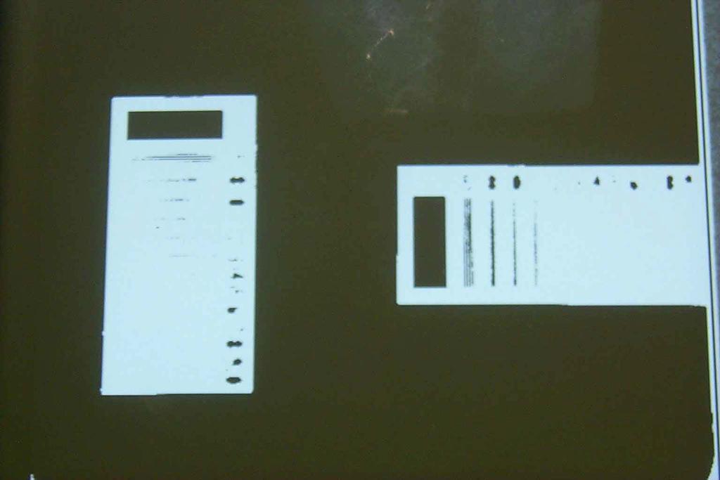
16 2. Collimation Assessment Radiation to digital image alignment Radiation beam confinement to image receptor

17 Coin Method


18 Monitor Film

19 Collimator Tool Method


20 Monitor Film
21 Collimation Tolerance The radiation field should extend beyond the image receptor But not more than 5 mm on any edge
22 Radiation Beam Confinement Often, the rad field will exceed the image receptor at the chest wall breast unnecessary radiation radiation field image field metal compression paddle

23 3. Focal Spot Performance The focal spot performance is tested with the res pattern and film (no screen)

24 Focal Spot Performance 11 lp/mm in the direction perpendicular to the anode cathode axis 13 lp/mm in the direction parallel to the anode cathode axis 13 parallel 11 perp
25 System Resolution (Digital) The resolution test pattern is used with the digital receptor to find limiting resolution of the 50x50 mm image size. For 512 image, pixel size is = mm = 5.1 lp/mm For 1024 image, pixel size is mm = 10.2 lp/mm Typically see 7-10 lp/mm
26
27 Q1- The maximum limiting system resolution for a dedicated SBB device in 1024 mode would be: 20% 20% 20% 20% 20% 1. 1 lp/mm 2. 3 lp/mm 3. 5 lp/mm 4. 7 lp/mm lp/mm 10
28 5. 10 lp/mm Bushberg, Jerrold T, Ph.D., et al; The Essential Physics of Medical Imaging, Second Edition; Lippincott, Williams & Wilkins, 2002, p. 284
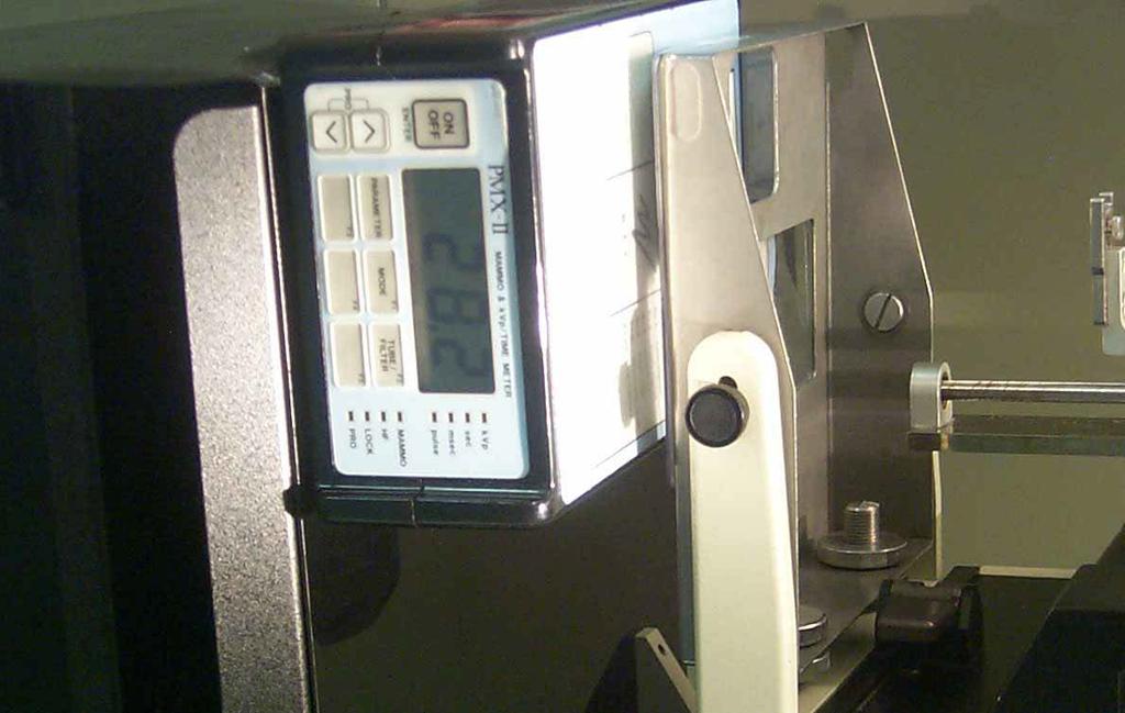
29 4. KVp Performance
30 kvp Accuracy and Reproducibility Mammography units should have clinically used kvp accuracy to within 5% of the indicated kvp From four measurements at most commonly used kvp, compute mean, s.d., and coefficient of variation (sd/mean) C.V. should be within 0.02
31 Q2- Tube potential accuracy should be within: 20% 20% 20% 20% 20% 1. 1 % 2. 1 kvp 3. 2 % 4. 2 kvp 5. 5 % 10
32 5. 5 % American College of Radiology; Stereotactic Breast Biopsy Quality Control Manual; 1999, p. 65
33 5. Beam Quality (HVL) The HVL requirements are slightly different from filmscreen mammo, because the image port is open (no paddle attenuation) The HVL should be above HVL kvp/100 (mm Al) The ACR suggests an upper limit of HVL < kvp/ (mm Al) for Mo/Mo At 28 kvp, 0.40 HVL 0.28

34 Half-Value Layer High-purity aluminum
35 Half-Value Layer Logarithmic interpolation can be are used to calculate HVL Using the logarithmic method, where E 0 =0 mm, E a = first added filtration, E b =second total added filtration HVL = t b ln (2E a / E o ) - t a ln (2E b / E o ) ln ( E a / E b )
36 Q3- The half-value layer (HVL) at 28 kvp must be greater than or equal to: 20% 20% 20% 20% 20% mm Al mm Al mm Al mm Al mm Al 10
37 mm Al American College of Radiology; Stereotactic Breast Biopsy Quality Control Manual; 1999, p. 68
38 6. AEC Performance (if used) For the performance test, 4, 6, and 8 cm of lucite is evaluated with clinical technique factors
39 AEC System Performance For digital systems: read the signal value in the center of the image signal from 6 and 8 cm should be within ± 20% of the 4 cm reading if not, a technique chart should be developed and posted

40 Technique Chart Posted techniques should be evaluated and adjusted to keep image quality high, yet exposure times < 2 seconds
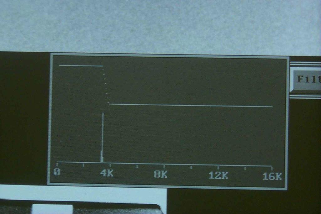
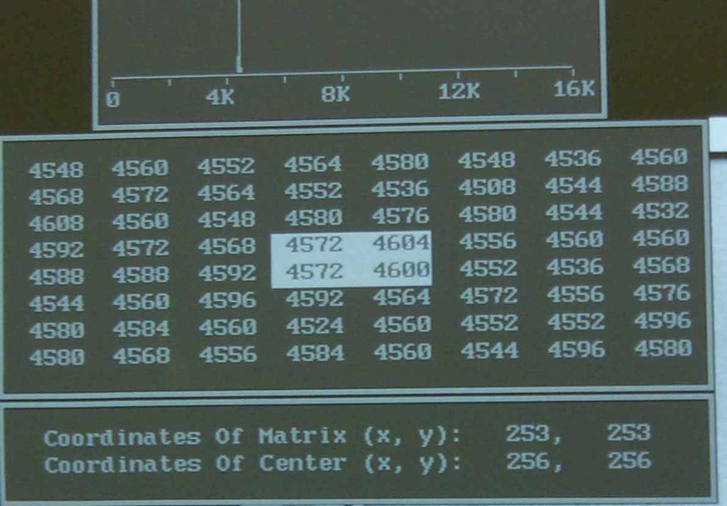
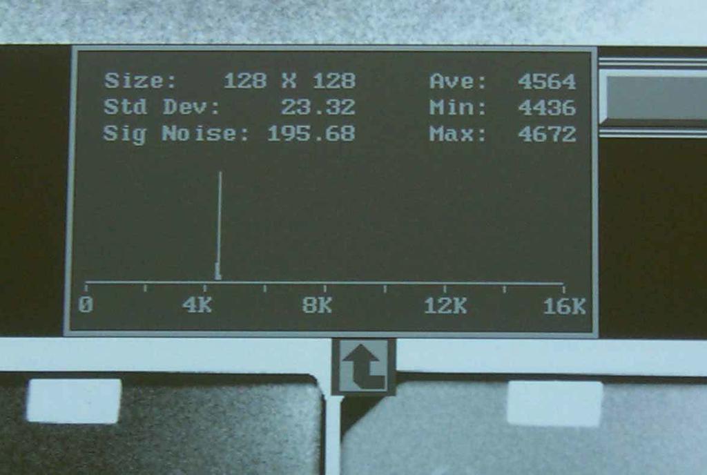
41 7. Digital Image Uniformity 4 cm lucite image Signal analysis in center and quadrants Signal Standard deviation (sd) SNR Calculate quadrant deviance from the center values Systems without ROI capability, use wire mesh pattern
42
43
44
45
46 Lorad Tolerances SNR in each corner ± 15% of center (early manuals show 128x128 box). I ve never found a Lorad unit that will pass with this protocol. Later test protocols use a 32x32 box and specifies the corner areas to sample. The specified tolerance was that the SNR in each corner not exceed ± 20% of the central SNR. Most units will pass with these parameters.
47 6% of total area 0.4% of total area 128x image 32x image
48 Newer Lorad Units On the latest units, the operator manual indicates to take signal in the center of 1024 image with 32x32 box (0.1% of total area). This also requires significantly more radiation to keep signal at 4k, when quadrupling image matrix. Signal in each quadrant should be within 15% of the center. All of them appear to be able to pass this protocol.
49 Fischer Tolerances SNR in each corner ± 15% of center (ACR manual shows 128x128 box) Most units will pass this tolerance
50 Q4- The ACR digital receptor uniformity tolerance for signal value is: 20% 20% 20% 20% 20% 1. 5 % % % % % 10
51 3. 15% American College of Radiology; Stereotactic Breast Biopsy Quality Control Manual; 1999, p. 75
52 8. Breast Radiation Dosimetry Find technique factors that give manufacturer recommended signal values for the ACR phantom or the mas given from an AEC technique. Position ion chamber in port at 4.5 cm from breast support. Measure manual exposure 4 times. For AEC techniques, use closest mas. Calculate average, s.d., and c.v. < 0.05

53 Breast Dose
54 Breast Dosimetry For AEC technique, calculate ESE from: ESE aec = ESE man (mas aec /mas man ) Calculate the average glandular dose from look-up table in ACR manual (kvp vs HVL) for Mo/Mo. Typical conversion factor is 0.18 at 28 kvp. Dose should be less than 3.0 mgy (300 mrad). (Michigan requires 2.0 mgy for all mammography)
55 9. Image Quality Make an exposure of the ACR phantom using the kvp and density normally used clinically. For the standard ACR phantom, image in each quadrant to determine IQ score. For the ACR mini-phantom, only one image is needed.
56 ACR Phantom Screen-film: Digital: 4.0 fibers, 3.0 specks, 3.0 masses 5.0 fibers, 4.0 specks, 3.5 masses

57 Mini-Phantom

58 Mini-Phantom Screen-film: Digital: 2.0 fibers, 2.0 specks, 2.0 masses 3.0 fibers, 3.0 specks, 2.5 masses
59 ACR Phantom Scoring Fibers are scored down to the smallest full or half fiber visible. A full point is given for full fiber, 0.5 for half. Specks are scored down to the smallest visible group. A full point is given if specks 4, 5, & 6 are visible, 0.5 if only 2 & 3 are visible, and 0 if only 1 speck is visible. Masses are scored down to the smallest visible. A full point is given if round and in the right location, a 0.5 point if in the right location but not round.
60 Score Subtraction for Artifacts If a fiber-like artifact is as apparent as an actual fiber, it is subtracted from the last half or full fiber. If speck-like artifacts are present, they are deducted on a one for one basis from the last group counted. If a mass-like artifact is as apparent as an actual mass, it is subtracted from the last real mass.
61
62 Mag Tool
63 Q5- The digital image quality required for the dedicated mini-phantom: 20% 20% 20% 20% 20% fibers, 4.0 specks, 4.0 masses fibers, 3.5 specks, 3.5 masses fibers, 3.5 specks, 3.5 masses fibers, 3.0 specks, 3.0 masses fibers, 3.0 specks, 2.5 masses 10
64 fibers, 3.0 specks, 2.5 masses American College of Radiology; Stereotactic Breast Biopsy Quality Control Manual; 1999, p. 91
65 10. Artifact Evaluation For digital IR image lucite sheet large enough to cover IR Adjust the window width and level to look for defects in the image

66 Very narrow window

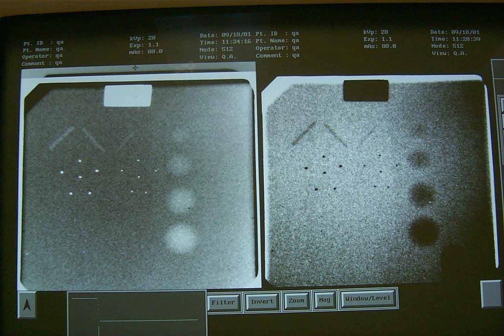
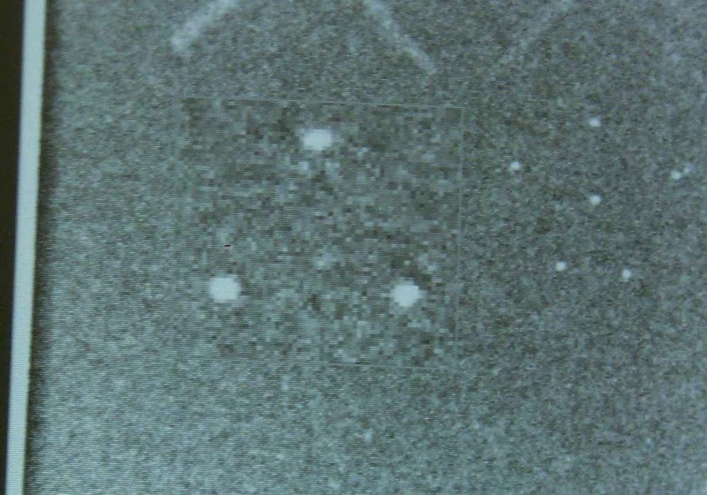
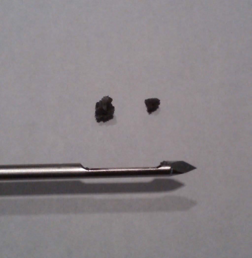
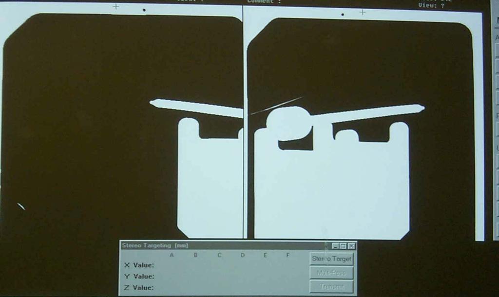
67 11. Localization Accuracy
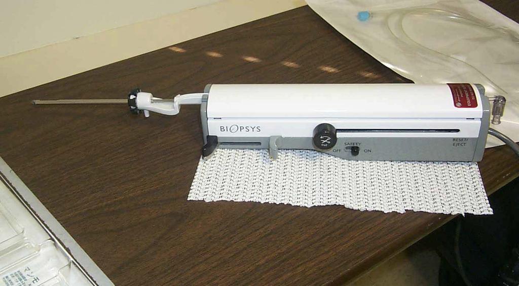
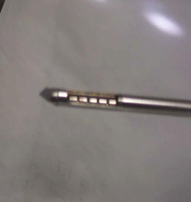
68 Mammotome

69

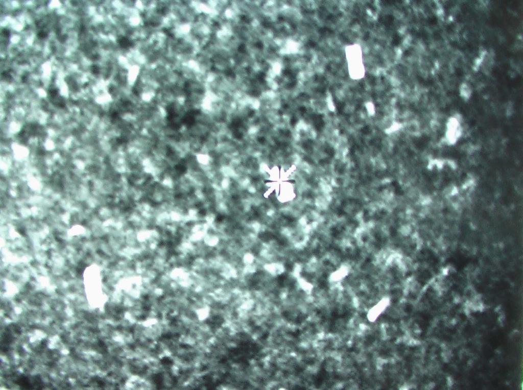
70 Scout Image (0 0 )

71 Stereo Scouts (+15 0, )
72

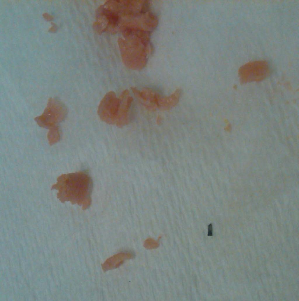
73 Oh Baloney!

74 Thin metal pieces

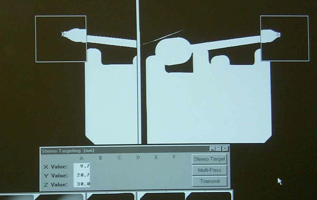
75 Stereo Scouts
76
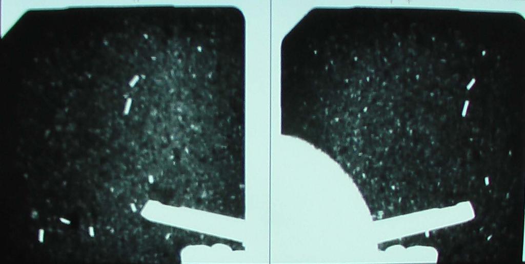
77 Pre-Fire
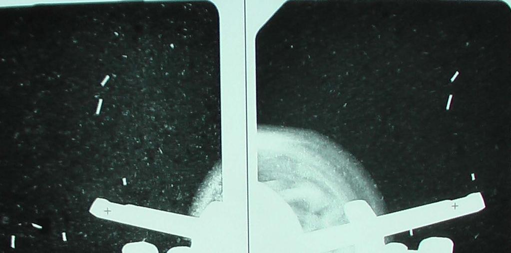
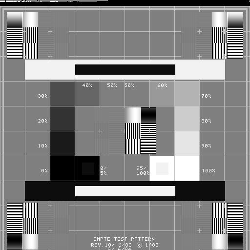
78 Post-Fire
79
80 Technologist s QC Zero Alignment - before each patient Localization Accuracy (XYZ) - each day of use Phantom Imaging - each week of use Visual Checklist - monthly Hardcopy QC - monthly (if applicable) Compression - semiannual Repeat Analysis - semiannual

81 Coordinates Calibration (XYZ)
82
83
84
85 Hardcopy QC (monthly) Print SMPTE pattern from console Print SMPTE from printer or Radiograph a step-wedge and print
86
87
88

89
90 Q6- The localization accuracy (in air) and phantom image quality should be conducted by the technologist: 20% 20% 20% 20% 20% 1. Daily, daily 2. Daily, weekly 3. Each day of use, weekly 4. Each day of use, each week of use 5. Weekly, weekly 10
91 4. Each day of use, each week of use American College of Radiology; Stereotactic Breast Biopsy Quality Control Manual; 1999, pp. 17&21
92
93 SUMMARY SBB-ACR accreditation is voluntary, for now Even though exempt from MQSA testing regimen, dedicated units should be tested routinely by the Medical Physicist, and may be required by state agencies.
Surveying and QC of Stereotactic Breast Biopsy Units for ACR Accreditation
 Surveying and QC of Stereotactic Breast Biopsy Units for ACR Accreditation AAPM Annual Clinical Meeting Indianapolis, IN August 5, 2013 Learning Objectives Become familiar with the recommendations and
Quality Control for Stereotactic Breast Biopsy. Robert J. Pizzutiello, Jr., F.A.C.M.P. Upstate Medical Physics, Inc
 Quality Control for Stereotactic Breast Biopsy Robert J. Pizzutiello, Jr., F.A.C.M.P. Upstate Medical Physics, Inc. 716-924-0350 Methods of Imaging Guided Breast Biopsy Ultrasound guided, hand-held needle
7/20/2014. Outline. Outline. Disclosures. Learning Objectives. SBB: Practical Aspects of ACR Accreditation, QC and ACR On Site Surveys
 Outline SBB: Practical Aspects of ACR Accreditation, QC and ACR On Site Surveys Robert J. Pizzutiello, MS, FACR, FAAPM, FAC Residency Program Director, Upstate Medical Physics, PC Senior Vice President,
Acceptance Testing of a Digital Breast Tomosynthesis Unit
 Acceptance Testing of a Digital Breast Tomosynthesis Unit 2012 AAPM Spring Clinical Meeting Jessica Clements, M.S., DABR Objectives Review of technology and clinical advantages Acceptance Testing Procedures
Practical Aspects of Medical Physics Surveys of Mammography Equipment and Facilities
 Practical Aspects of Medical Physics Surveys of Mammography Equipment and Facilities Melissa Martin, M.S., FAAPM, FACR, FACMP AAPM Annual Meeting - Philadelphia July 19, 2010 MO-B-204C-1 Educational Objectives
Quality Control of Full Field Digital Mammography Units
 Quality Control of Full Field Digital Mammography Units Melissa C. Martin, M.S., FACMP, FACR, FAAPM Melissa@TherapyPhysics.com 310-612-8127 ACMP Annual Meeting Virginia Beach, VA May 2, 2009 History of
Introduction. Digital Mammography QA: Comparing the Manufacturers Recommendations. What is QC and why is it important? Review & compare QC tests
 Slide 1 Digital Mammography QA: Comparing the Manufacturers Recommendations Eric A. Berns, Ph.D. Slide 2 Introduction What is QC and why is it important? Review & compare QC tests Key take home points
Investigation of the line-pair pattern method for evaluating mammographic focal spot performance
 Investigation of the line-pair pattern method for evaluating mammographic focal spot performance Mitchell M. Goodsitt, a) Heang-Ping Chan, and Bob Liu Department of Radiology, University of Michigan, Ann
Nuclear Associates
 Nuclear Associates 07-647 R/F QC Phantom Operators Manual March 2005 Manual No. 07-647-1 Rev. 2 2004, 2005 Fluke Corporation, All rights reserved. All product names are trademarks of their respective companies
Ansur TNT Users Manual. Plug-In
 Ansur TNT 12000 Plug-In Users Manual August 2009, Rev. 2, 12/09 2009 Fluke Corporation. All rights reserved. Specifications are subject to change without notice. All product names are trademarks of their
REQUIREMENTS FOR LICENCE HOLDERS WITH RESPECT TO QUALITY CONTROL TESTS FOR DIAGNOSTIC X-RAY IMAGING SYSTEMS
 REQUIREMENTS FOR LICENCE HOLDERS WITH RESPECT TO QUALITY CONTROL TESTS FOR DIAGNOSTIC X-RAY IMAGING SYSTEMS DEPARTMENT OF HEALTH DIRECTORATE: RADIATION CONTROL Implementation date: 31 March 2009 Contents
NJDEP Medical Physicist s Radiographic QC Survey Registration Number:
 Facility Name NJDEP ID # NJDEP Medical Physicist s Radiographic QC Survey PLEASE PRINT Facility Information Unit Information Manufacturer Model Console Model # Console serial # Tube serial # Location (room)
Breast Tomosynthesis. Bob Liu, Ph.D. Department of Radiology Massachusetts General Hospital And Harvard Medical School
 Breast Tomosynthesis Bob Liu, Ph.D. Department of Radiology Massachusetts General Hospital And Harvard Medical School Outline Physics aspects of breast tomosynthesis Quality control of breast tomosynthesis
Y11-DR Digital Radiography (DR) Image Quality
 Image Quality") Y11-DR Digital Radiography (DR) Image Quality Image quality is stressed for all systems in Safety Code 35. In the relevant sections Health Canada s advice is the manufacturer s recommended test procedures
Y11-DR Digital Radiography (DR) Image Quality Image quality is stressed for all systems in Safety Code 35. In the relevant sections Health Canada s advice is the manufacturer s recommended test procedures
4/19/2016. Quality Control Activities for the RadiologicTechnologist. Objectives. 3D Tomosynthesis QC differences
 Quality Control Activities for the RadiologicTechnologist Quality Control Tests 2D QC Tomosynthesis QC DICOM Printer Quality Control Weekly Detector Flat Field Calibration Weekl Artifact Evaluation Weekly
I. PERFORMANCE OF X-RAY PRODUCTION COMPONENTS FLUOROSCOPIC ACCEPTANCE TESTING: TEST PROCEDURES & PERFORMANCE CRITERIA
 FLUOROSCOPIC ACCEPTANCE TESTING: TEST PROCEDURES & PERFORMANCE CRITERIA EDWARD L. NICKOLOFF DEPARTMENT OF RADIOLOGY COLUMBIA UNIVERSITY NEW YORK, NY ACCEPTANCE TESTING GOALS PRIOR TO 1st CLINICAL USAGE
Overview of Safety Code 35
 Common Quality Control Procedures for All s Quality Control Procedures Film All s Daily Quality Control Tests Equipment Warm-up (D1) According to manufacturers instructions Can include auto calibration(d1)
8/2/2017. Radiologist Responsibilities. Radiologist Responsibilities. Medical Physicist Mammography Equipment Evaluation and Annual Survey
 Implementation of the 2016 ACR Digital Mammography QC Manual Medical Physicist Mammography Equipment Evaluation and Annual Survey Eric A Berns, PhD, FACR Radiologist Responsibilities Radiologist Responsibilities
Aspire HD. Program Manual. 2nd Edition - October 2012
 Quality Control 1 Aspire HD Quality Control Program Manual 2nd Edition - October 2012 Overview Installation of FDR Mammography QC Program Weekly Test 2 3 4 Quarterly Test 5 Semi-annual Test 6 Annual Test
Nuclear Associates
 Nuclear Associates 07-649 CDRH Fluoroscopic Phantom Users Manual March 2005 Manual No. 07-649-1 Rev. 2 2004, 2005 Fluke Corporation, All rights reserved. Printed in U.S.A. All product names are trademarks
FFDM -FCRm QC Requirements- What You REALLY Need to Know
 FFDM -FCRm QC Requirements- What You REALLY Need to Know Melissa C. Martin, M.S., FACR, FAAPM, FACMP AAPM Annual Meeting July 28, 2008 FDA Approval for Mammography Fuji FCRm System approved for Mammography
FFDM in the Field: Physicist's Role in the QC of Mammography Laser Printers May Carl R. Keener, Ph.D., DABMP, DABR
 FFDM in the Field: Physicist's Role in the QC of Mammography Laser Printers May 2010 Carl R. Keener, Ph.D., DABMP, DABR keener@marpinc.com MARP Medical & Radiation Physics, Inc. Physicist's Role in the
Mammography is a radiographic procedure specially designed for detecting breast pathology Approximately 1 woman in 8 will develop breast cancer over
 Mammography is a radiographic procedure specially designed for detecting breast pathology Approximately 1 woman in 8 will develop breast cancer over a lifetime Breast cancer screening programs rely on
Test Equipment for Radiology and CT Quality Control Contents
 Test Equipment for Radiology and CT Quality Control Contents Quality Control Testing...2 Photometers for Digital Clinical Display QC...3 Primary Workstations...3 Secondary Workstations...3 Testing of workstations...3
Facility, Unit and Test Equipment Data
 Facility, Unit and Test Equipment Data Medical hysicist's Tests - SAMLE FORMS Facility Information Facility Name Happy Valley Mammography Address Suite 1 Address 1 Oak Street City, State, Zip Anywhere
TESTING FLAT-PANEL IMAGING SYSTEMS: What the Medical Physicist Needs to Know. JAMES A. TOMLINSON, M.S., D.A.B.R. Diagnostic Radiological Physicist
 TESTING FLAT-PANEL IMAGING SYSTEMS: What the Medical Physicist Needs to Know JAMES A. TOMLINSON, M.S., D.A.B.R. Diagnostic Radiological Physicist Topics Image Uniformity and Artifacts Image Quality - Detail
Exposure Indices and Target Values in Radiography: What Are They and How Can You Use Them?
 Exposure Indices and Target Values in Radiography: What Are They and How Can You Use Them? Definition and Validation of Exposure Indices Ingrid Reiser, PhD DABR Department of Radiology University of Chicago
Mammography: Physics of Imaging
 Mammography: Physics of Imaging Robert G. Gould, Sc.D. Professor and Vice Chair Department of Radiology and Biomedical Imaging University of California San Francisco, California Mammographic Imaging: Uniqueness
MILADY. Product Data. Page 1 of 8
 Page 1 of 8 The MILADY Mammographic Unit offers the best quality-to-price ratio to our customers worldwide. The unit advanced technology together with the application of industrial production standards,
Collimation Assessment Using GAFCHROMIC XR-M2
 Collimation Assessment Using GAFCHROMIC XR-M2 I. Introduction A method of collimation assessment for GE Senographe full-field digital mammography (FFDM) systems is described that uses a self-developing
QC Testing for Computed Tomography (CT) Scanner
 Scanner") QC Testing for Computed Tomography (CT) Scanner QA - Quality Assurance All planned and systematic actions needed to provide confidence on a structure, system or component. all-encompassing program, including
QC Testing for Computed Tomography (CT) Scanner QA - Quality Assurance All planned and systematic actions needed to provide confidence on a structure, system or component. all-encompassing program, including
Ludlum Medical Physics
 Ludlum Medical Physics Medical Imaging Radiology QA Test Tools NEW LUDLUM PRODUCT LINE Medical Physics Products Medical Physics Products What are they? Products used to measure radiation output and to
Features and Weaknesses of Phantoms for CR/DR System Testing
 Physics testing of image detectors Parameters to test Features and Weaknesses of Phantoms for CR/DR System Testing Spatial resolution Contrast resolution Uniformity/geometric distortion Dose response/signal
MAMMOGRAPHY - HIGH LEVEL TROUBLESHOOTING
 MAMMOGRAPHY - HIGH LEVEL TROUBLESHOOTING Maynard High New York Medical College SS2001-M.High 1 Objectives: Review MQSA and ACR annual QC tests as opportunities for troubleshooting before a significant
Quality control for digital mammography: Part II recommendations from the ACRIN DMIST trial
 Quality control for digital mammography: Part II recommendations from the ACRIN DMIST trial Martin J. Yaffe, Aili K. Bloomquist, Gordon E. Mawdsley, Etta D. Pisano, R. Edward Hendrick, Laurie L. Fajardo,
DISC QC/QA Program for Digital Imaging Systems using the DR Radchex Plus Meter
 DISC QC/QA Program for Digital Imaging Systems using the DR Radchex Plus Meter Revision Date: January 5th, 2017 www.disc-imaging.com Table of Contents Section A: Preliminary Setup Requirements... 4 Tools
Published text: Institute of Cancer Research Repository Please direct all s to:
 This is an author produced version of an article that appears in: MEDICAL PHYSICS The internet address for this paper is: https://publications.icr.ac.uk/1316/ Copyright information: http://www.aip.org/pubservs/web_posting_guidelines.html
Beam-Restricting Devices
 Beam-Restricting Devices Three factors contribute to an increase in scatter radiation: Increased kvp Increased Field Size Increased Patient or Body Part Size. X-ray Interactions a some interact with the
Introduction of Computed Radiography in Two Mammography Services: Image Quality and Dose Analysis
 Introduction of Computed Radiography in Two Mammography Services: Image Quality and Dose Analysis Rosangela Requi Jakubiak* a, Humberto Remigio Gamba a, Maria Manuela Ramos a, Gislene Gabrielle Faversani
Half value layer and AEC receptor dose compliance survey in Estonia
 Half value layer and AEC receptor dose compliance survey in Estonia K. Kepler, A. Vladimirov Training Centre of Medical Physics, University of Tartu Testing Centre of the University of Tartu, Estonia E-mail:
Exposure System Selection
 Principles of Imaging Science II (RAD120) Exposure Systems Exposure System Selection Radiographic exposure is a very complex process Best technique systems manipulate one variable while holding others
diagnostic examination
 RADIOLOGICAL PHYSICS 2011 Raphex diagnostic examination Adel A. Mustafa, Ph.D., Editor PUBLISHED FOR: RAMPS (Radiological and Medical Physics Society of New York) preface The RAPHEX Diagnostic exam 2011
Digital Imaging started in the 1972 with Digital subtraction angiography Clinical digital imaging was employed from the 1980 ~ 37 years ago Amount of
 Digital Imaging started in the 1972 with Digital subtraction angiography Clinical digital imaging was employed from the 1980 ~ 37 years ago Amount of radiation to the population due to Medical Imaging
DIAGNOSTIC ACCREDITATION PROGRAM. Radiology and CT Quality Control Procedures Workbook
 DIAGNOSTIC ACCREDITATION PROGRAM Radiology and CT Quality Control Procedures Workbook Quality Control Procedures Radiography/CR/DR Safety Code 35 Summary For more detail about each quality control (QC)
QUALITY CONTROL TESTS IN SOME DIAGNOSTIC X-RAY UNITS IN BANGLADESH
 Bangladesh Journal of Medical Physics Vol. 4, No.1, 2011 QUALITY CONTROL TESTS IN SOME DIAGNOSTIC X-RAY UNITS IN BANGLADESH M. Begum 1, A. S. Mollah 2, M. A. Zaman 3 and A. K. M. M. Rahman 4 1 Health Physics
TOPICS: CT Protocol Optimization over the Range of Patient Age & Size and for Different CT Scanner Types: Recommendations & Misconceptions
 CT Protocol Optimization over the Range of Patient Age & Size and for Different CT Scanner Types: Recommendations & Misconceptions TOPICS: Computed Tomography Quick Overview CT Dosimetry Effects of CT
QC in Diagnostic Radiology. Main steps for a QC survey in Diagnostic Radiology
 EVALUATING X-RAY TUBE AND GENERATOR PERFORMANCE : DEMO for PRACTICAL QUALITY CONTROL (QC) Dr Slavik Tabakov Dept. Medical Eng. & Physics, King's College London slavik.tabakov@kcl.ac.uk QC in Diagnostic
GE Healthcare. Performa. High-performance breast imaging
 GE Healthcare Performa High-performance breast imaging Moving mammography forward. And patients faster. GE Healthcare s unparalleled leadership across mammography begins with a deep understanding of breast
Learning Objectives: What s my motivation? (unknown screen actor) Workshop Overview
 Workshop Overview") Practical Medical Physics Adapting Traditional Clinical Medical Physics to Digital Radiography Charles E. Willis, Ph.D., DABR Associate Professor Department of Imaging Physics The University of Texas M.D.
Practical Medical Physics Adapting Traditional Clinical Medical Physics to Digital Radiography Charles E. Willis, Ph.D., DABR Associate Professor Department of Imaging Physics The University of Texas M.D.
Overview. Professor Roentgen was a Physicist!!! The Physics of Radiation Oncology X-ray Imaging
 The Physics of Radiation Oncology X-ray Imaging Charles E. Willis, Ph.D. DABR Associate Professor Department of Imaging Physics The University of Texas M.D. Anderson Cancer Center Houston, Texas Overview
THE ART OF THE IMAGE: IDENTIFICATION AND REMEDIATION OF IMAGE ARTIFACTS IN MAMMOGRAPHY
 THE ART OF THE IMAGE: IDENTIFICATION AND REMEDIATION OF IMAGE ARTIFACTS IN MAMMOGRAPHY William Geiser, MS DABR Senior Medical Physicist MD Anderson Cancer Center Houston, Texas wgeiser@mdanderson.org INTRODUCTION
TECHNICAL DATA. GIOTTO IMAGE SDL/W is pre-arranged for Full Field Digital Biopsy examination with the patient in prone position.
 Ver. 01/06/07 TECHNICAL DATA GIOTTO IMAGE SDL/W LOW DOSE, FULL FIELD DIGITAL MAMMOGRAPHY UNIT USING AMORPHOUS SELENIUM (a-se) TECHNOLOGY DETECTOR (pre-arranged for stereotactic biopsy with the same digital
Image Display and Perception
 Image Display and Perception J. Anthony Seibert, Ph.D. Department of Radiology UC Davis Medical Center Sacramento, California, USA Image acquisition, display, & interpretation X-rays kvp mas Tube filtration
Digital radiography (DR) post processing techniques for pediatric radiology
 post processing techniques for pediatric radiology") Digital radiography (DR) post processing techniques for pediatric radiology St Jude Children s Research Hospital Samuel Brady, MS PhD DABR samuel.brady@stjude.org Purpose Review common issues and solutions
Digital radiography (DR) post processing techniques for pediatric radiology St Jude Children s Research Hospital Samuel Brady, MS PhD DABR samuel.brady@stjude.org Purpose Review common issues and solutions
Breast Imaging Basics: Module 10 Digital Mammography
 Module 10 Transcript For educational and institutional use. This test bank is licensed for noncommercial, educational inhouse or online educational course use only in educational and corporate institutions.
ACPSEM Position Paper RECOMMENDATIONS FOR A DIGITAL MAMMOGRAPHY QUALITY ASSURANCE PROGRAM V4.0
 Heggie et al ACPSEM Position Paper: Digital Mammography V4.0 ACPSEM Position Paper RECOMMENDATIONS FOR A DIGITAL MAMMOGRAPHY QUALITY ASSURANCE PROGRAM V4.0 JCP Heggie 1, P Barnes 2, L Cartwright 3, J Diffey
Safelight Fog does what to contrast and density on film?
 Terri Jurkiewicz Safelight Fog does what to contrast and density on film? ANSWER INCREASES DENSITY DECREASES CONTRAST Explain how you determine if the focal spot size is within appropriate limits.
Introduction. Chapter 16 Diagnostic Radiology. Primary radiological image. Primary radiological image
 Introduction Chapter 16 Diagnostic Radiology Radiation Dosimetry I Text: H.E Johns and J.R. Cunningham, The physics of radiology, 4 th ed. http://www.utoledo.edu/med/depts/radther In diagnostic radiology
Nuclear Associates
 Nuclear Associates 07-644 Grid Alignment Test Tool Users Manual March 2005 Manual No. 07-644-1 Rev. 2 2004, 2005 Fluke Corporation, All rights reserved. Printed in U.S.A. All product names are trademarks
7/24/2014. Image Quality for the Radiation Oncology Physicist: Review of the Fundamentals and Implementation. Disclosures. Outline
 Image Quality for the Radiation Oncology Physicist: Review of the Fundamentals and Implementation Image Quality Review I: Basics and Image Quality TH-A-16A-1 Thursday 7:30AM - 9:30AM Room: 16A J. Anthony
Unit thickness. Unit area. σ = NΔX = ΔI / I 0
 Unit thickness I 0 ΔI I σ = ΔI I 0 NΔX = ΔI / I 0 NΔX Unit area Δx Average probability of reaction with atom for the incident photons at unit area with the thickness of Delta-X Atom number at unit area
The Evaluation of Collimator Alignment of Diagnostic X-ray Tube Using Computed Radiography System
 The Evaluation of Collimator Alignment of Diagnostic X-ray Tube Using Computed Radiography System The Evaluation of Collimator Alignment of Diagnostic X-ray Tube Using Computed Radiography System Manus
New spectral benefi ts, proven low dose
 New spectral benefi ts, proven low dose Philips MicroDose mammography SI, technical data sheet Philips MicroDose SI with single-shot spectral imaging is a fullfi eld digital mammography solution that delivers
SPECIFICATION. Kilovoltage X-ray calibration system for protection and diagnostic level dosimetry. Prepared by
 SPECIFICATION Kilovoltage X-ray Prepared by Igor Gomola, Technical Officer, Project ECU6023, Date 2015-Oct-06 Revision Date Status Comments 0.1 2015-Oct-06 Draft Igor Gomola Page 1 of 12 1. Scope This
Imaging Technique Optimization of Tungsten Anode FFDM System
 Imaging Technique Optimization of Tungsten Anode FFDM System Biao Chen a*, Andrew P. Smith b, Zhenxue Jing a, Elena Ingal a a Hologic, Inc. 600 Technology Drive, DE 1970 b Hologic, Inc. 35 Crosby Drive,
Image Quality. HTC Grid High Transmission Cellular Grid provides higher contrast images
 B R E A S T I M A G I N G S O L U T I O N S Setting the benchmark for mammography M-IV Series Innovations in breast imaging The Lorad M-IV Series exemplifies Hologic's commitment to developing advanced
Protocol for the Quality Control of the Physical and Technical Aspects of Digital Breast Tomosynthesis Systems
 Protocol for the Quality Control of the Physical and Technical Aspects of Digital Breast Tomosynthesis Systems Draft version 0.10 February 2013 European Reference Organisation for Quality Assured Breast
RAD 150 RADIOLOGIC EXPOSURE TECHNIQUE II
 RAD 150 RADIOLOGIC EXPOSURE TECHNIQUE II APPROVED 12/O2/2011 EFFECTIVE SPRING 2013-14 Prefix & Number RAD 150 Course Title: Radiologic Exposure Technique II & Lab Purpose of this submission: New Change/Updated
of sufficient quality and quantity
 of sufficient quality and quantity The patient s body attenuates the beam as it passes though the body More energy is deposited in organs located near the entry of the beam than near the exit of the beam
LECTURE 1 The Radiographic Image
 LECTURE 1 The Radiographic Image Prepared by:- KAMARUL AMIN ABDULLAH @ ABU BAKAR UiTM Faculty of Health Sciences Medical Imaging Department 11/23/2011 KAMARUL AMIN (C) 1 Lesson Objectives At the end of
KODAK DIRECTVIEW CR Mammography Feature User s Guide
 KODAK DIRECTVIEW CR Mammography Feature User s Guide 17 September 2010 9G3741 Version 1.0 Carestream Health, Inc. 150 Verona Street Rochester, NY 14608 CARESTREAM, DIRECTVIEW, and DRYVIEW are trademarks
Diagnostic x-ray equipment compliance and facility survey
 Canada Health Canada Canada CA9600871 CA9600871 Diagnostic x-ray equipment compliance and facility survey Diagnostic x-ray equipment compliance and facility survey Recommended procedures for equipment
Assessment of Beam Alignment, Collimation and Half Value Layer of Some Selected X-Ray Machines in Plateau State, Nigeria
 International Journal of Innovative Scientific & Engineering Technologies Research 5(4):-5, Oct.-Dec., 07 SEAHI PUBLICATIONS, 07 www.seahipaj.org ISSN: 60-896X Assessment of Beam Alignment, Collimation
ABOVETABLE X-RAY SOURCE FLUOROSCOPIC AND SPOT-FILM SYSTEMS
 PART VI ABOVETABLE X-RAY SOURCE FLUOROSCOPIC AND SPOT-FILM SYSTEMS FORM FDA 3069 REPRINTED April 2000 ROUTINE COMPLIANCE TESTING ABOVETABLE X-RAY SOURCE FLUOROSCOPIC AND SPOT-FILM SYSTEMS (Test Procedure
X-ray Tube and Generator Basic principles and construction
 X-ray Tube and Generator Basic principles and construction Dr Slavik Tabakov - Production of X-rays OBJECTIVES - X-ray tube construction - Anode - types, efficiency - X-ray tube working characteristics
CHAPTER 6 QC Test For Fluoroscopic Equipment. Prepared by:- Kamarul Amin bin Abu Bakar School of Medical Imaging KLMUC
 CHAPTER 6 QC Test For Fluoroscopic Equipment Prepared by:- Kamarul Amin bin Abdullah @ Abu Bakar School of Medical Imaging KLMUC Lesson Outcomes Describe the objectives of each QC test done. Identify QC
History of digital imaging
 CR/QA RADCHEX History of digital imaging Early, crude digital detectors were developed in the 1970 s Image quality was problematic Processing time of digital images was untenable Viewing, transfer and
Dose Reduction and Image Preservation After the Introduction of a 0.1 mm Cu Filter into the LODOX Statscan unit above 110 kvp
 Dose Reduction and Image Preservation After the Introduction of a into the LODOX Statscan unit above 110 kvp Abstract: CJ Trauernicht 1, C Rall 1, T Perks 2, G Maree 1, E Hering 1, S Steiner 3 1) Division
Essentials of Digital Imaging
 Essentials of Digital Imaging Module 7 Transcript 2016 ASRT. All rights reserved. Essentials of Digital Imaging Module 7 Quality 1. ASRT Animation 2. Welcome Welcome to the Essentials of Digital Imaging:
COMPUTED RADIOGRAPHY CHAPTER 4 EFFECTIVE USE OF CR
 This presentation is a professional collaboration of development time prepared by: Rex Christensen Terri Jurkiewicz and Diane Kawamura New Technology https://www.youtube.com/watch?v=ptkzznazb 7U COMPUTED
Calibration of KAP meters
 Calibration of KAP meters Alexandr Malusek! Division of Radiological Sciences Department of Medical and Health Sciences Linköping University! 2014-04-15 1 Outline 1. KAP meter construction 2. Air kerma-area
Image Quality. HTC Grid High Transmission Cellular Grid provides higher contrast images
 B R E A S T I M A G I N G S O L U T I O N S Setting the benchmark for mammography M-IV Series Innovations in breast imaging The Lorad M-IV Series exemplifies Hologic s commitment to developing advanced
Predicted image quality of a CMOS APS X-ray detector across a range of mammographic beam qualities
 Journal of Physics: Conference Series PAPER OPEN ACCESS Predicted image quality of a CMOS APS X-ray detector across a range of mammographic beam qualities Recent citations - Resolution Properties of a
Digital Breast Tomosynthesis
 Digital Breast Tomosynthesis OLIVE PEART MS, RT(R) (M) HTTP://WWW.OPEART.COM 2D Mammography Not 100% effective Limited by tissue superimposition Overlapping tissue can mask tumors False negative Overlapping
GE AMX 4+ Portable X-Ray
 GE AMX 4+ Portable X-Ray Typical Manufacturer s Picture GE Healthcare s AMX-4+ analog X-ray system provides high-performance in a compact, easy-to-maneuver package. The rotating arm and tube simplify positioning
Seminar 8. Radiology S8 1
 Seminar 8 Radiology Medical imaging. X-ray image formation. Energizing and controlling the X-ray tube. Image detectors. The acquisition of analog and digital images. Digital image processing. Selected
Unfors EDD-30 Radiation Protection in Fluoroscopy
 Unfors EDD-30 Radiation Protection in Fluoroscopy Immediate Warning Decrease Your Dose Interventional radiology procedures are considered to be essential to medical diagnosis and treatment. It is recognized,
ODYSSEY HF SERIES. ULTRA High Frequency X-Ray Technology. Precision... Performance... Power. Innovations in Digital Imaging.
 ODYSSEY HF SERIES ULTRA High Frequency X-Ray Technology Precision... Performance... Power Innovations in Digital Imaging. TM STEP 1 Select anatomical region STEP 2 Select anatomical view STEP 3 Ready for
T h e P h a n t o m L a b o r a t o r y
 T h e P h a n t o m L a b o r a t o r y 1 CCT228 ATCM Phantom Manual Copyright 2017 WARRANTY THE PHANTOM LABORATORY INCORPORATED ( Seller ) warrants that this product shall remain in good working order
Nuclear Associates
 Nuclear Associates 07-706 Patient Phantom/Penetrometer System Users Manual March 2005 Manual No. 07-706-1 Rev. 2 2004, 2005 Fluke Corporation, All rights reserved. Printed in U.S.A. All product names are
Radiographic Techniques, Contrast, and Noise in X-Ray Imaging
 Residents Section Physics Minimodule Huda and Abrahams Techniques, Contrast, and Noise in Radiography Residents Section Physics Minimodule Residents inradiology Walter Huda 1 R. Brad Abrahams 2 Huda W,
Title: A COMPARISON OF Cs-137 AND X-RAY SOURCES AS CALIBRATION REFERENCES FOR THERMOLUMINESCENT DOSIMETER CHIPS
 Title: A COMPARISON OF Cs-137 AND X-RAY SOURCES AS CALIBRATION REFERENCES FOR THERMOLUMINESCENT DOSIMETER CHIPS By Aravind Ravichandran arr192@mail.usask.ca University of Saskatchewan Address: 2424 Cumberland
Protocol for the Quality Control of the Physical and Technical Aspects of Digital Breast Tomosynthesis Systems
 Protocol for the Quality Control of the Physical and Technical Aspects of Digital Breast Tomosynthesis Systems Draft version 0.15 January 2014 European Reference Organisation for Quality Assured Breast
Outline. Digital Radiography. Understanding Digital Modalities: Image Quality and Dose. Image Quality. Dose Control
 Understanding Digital Modalities: Image Quality and Dose S. Jeff Shepard, M.S. University of Texas M. D. Anderson Cancer Center Houston, Texas Special Acknowledgement: Stephen K. Thompson, M.S. William
Comparison of computed radiography and filmõscreen combination using a contrast-detail phantom
 JOURNAL OF APPLIED CLINICAL MEDICAL PHYSICS, VOLUME 4, NUMBER 1, WINTER 2003 Comparison of computed radiography and filmõscreen combination using a contrast-detail phantom Z. F. Lu,* E. L. Nickoloff, J.
Mammograph FFDM PRODUCT DATA
 PRODUCT DATA Product data Rev.1 (May 2010) Page Description and Configurations 3 Technical Features 7 Mammography Unit 8 Acquisition Unit 12 Diagnostic Unit (Optional) 12 Size and Dimensions 13 Classifications
FMT18 FLOOR MOUNTED SYSTEM
 mas Time AEC 320 kvp 64 mas 320 ma 320 ma 320 DEN 0.0 mm Cu 17 in X 17 in 72.0 in FMT18 FLOOR MOUNTED SYSTEM with Synchronized Tracking System Overview Clinical Efficiency The FMT18 System was designed
Digital Radiography System
 www.drgem.co.kr GXR-SD SERIES GXR-SD SERIES Digital Radiography System GXR-SD Series www.drgem.co.kr High Performance and Reliability The Optimal System for Digital Solution The GXR-SD Series is a diagnostic
Automated dose control in multi-slice CT. Nicholas Keat Formerly ImPACT, St George's Hospital, London
 Automated dose control in multi-slice CT Nicholas Keat Formerly ImPACT, St George's Hospital, London Introduction to presentation CT contributes ~50+ % of all medical radiation dose Ideally all patients
Teaching Digital Radiography and Fluoroscopic Radiation Protection
 Teaching Digital Radiography and Fluoroscopic Radiation Protection WCEC 20 th Student Educator Radiographer Conference Dennis Bowman, RT(R), CRT (R)(F) Community Hospital of the Monterey Peninsula (CHOMP)