4/19/2016. Quality Control Activities for the RadiologicTechnologist. Objectives. 3D Tomosynthesis QC differences
|
|
|
- Solomon Johns
- 5 years ago
- Views:
Transcription


 5 additional exposures for the Tomosynthesis Gain Calibration")
1 Quality Control Activities for the RadiologicTechnologist Quality Control Tests 2D QC Tomosynthesis QC DICOM Printer Quality Control Weekly Detector Flat Field Calibration Weekl Artifact Evaluation Weekly Phantom Image Weekly Signal-To-Noise and Contrast-To- Noise Measurements weekly Compression Thickness Indicator Biweekly Diagnostic Review Workstation Quality Control Weekly Viewboxes and Viewing Conditions Weekly Visual Checklist Monthly Repeat/Reject Analysis Quarterly Compression Semiannually 1. Detector Flat Field Calibration 2. Geometry Calibration (Tomosynthesis option only) 3. Artifact Evaluation- Detector 4. Phantom Objectives 3D Tomosynthesis QC differences 2D Quality Control Review current 2D required tests QC Differences Identify the changes between 2D and tomosynthesis QC Tomosynthesis Quality Control Discuss what s required, objective, implementation, frequency and criteria Detector Flat-Field Calibration (Gain Calibration) 5 additional exposures for the Tomosynthesis Gain Calibration with Al (aluminum) filter Geometry Calibration 1 exposure Artifact Evaluation 1 additional Tomosynthesis Artifact Evaluation image Phantom Image Quality Evaluation 1 additional Tomosynthesis Phantom image (Combo exposure vs. a 2D exposure) 12 Quality Control Test 3D Tomosynthesis QC for GE MTD is Motorized Tomosynthesis Device 1


2 2


3 3


4 Quality Control Don t forget your technique chart Quality control is the part of the quality assurance program that deals with techniques used in monitoring and maintenance of the technical elements of the systems that affect the quality of the image. Level I Noninvasive and Simple Level II Noninvasive and Complex Level III Invasive and Complex That was then..this is now Old Terms Film screen contact Screen cleaning Darkroom Fog Fixer Rentention New Terms Flat Field Uniformity MTF CNR SNR Flat Field uniformity is an analysis of the homogeneity of the detector field MTF Modulation Transfer Function is a measure of image sharpness. CNR Contrast to noise ratio is a measure of the detectors ability to distinguish between objects in an image and the image noise. SNR Signal to noise Ratio compares the level of the desired signal to the level of background noise. A higher SNR provides a better image. 4


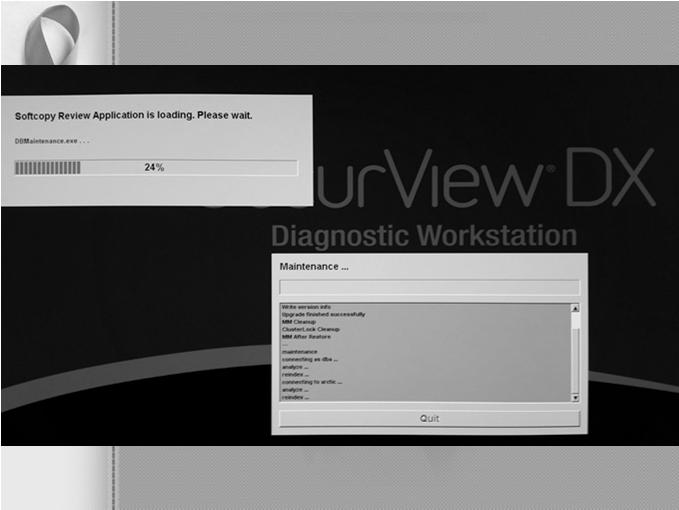
5 Status Detector must go from a Detector warming status to an All Ready status before any image quality test is performed Make sure paddle clamp is out of the way and remove all paddles to start quality control Any steps in the QC test procedures that are specific to digital breast Tomosynthesis are indicated by the wording "Tomosynthesis Option" and the icon on the side of the step. Quality Control Icon Quality Control icon which is accessed via the Admin page which is visible at the top. Green check mark means all ready Once the Quality Control icon is selected, it opens up to display all required Quality Control tests. 5


6 Technologists QC When beginning Quality Control, there are two tabs. One tab is for the Radiologic Technologist, and the other tab is for the Medical Physicist. For test that do not require any image acquisition, the operator has the ability to complete the test and select the Mark Completed button to close the test and update the information. Please note the revert completed tab. This tab is beneficial if a technologist marks a test competed by mistake and wishes to change the status of the completion. QC Report Hologic Proprietary Information for Training Purposes Only MED00012 The QC Report is an optional feature. The report list each test with a completion date and time. It also records the technologist that performed the exam. This report can be exported in two different formats; HTML or a CSV. HTML (hyper text mark-up level) is what they are currently useing. The other one, CSV (comma separated value) is more in the form of an excel spreadsheet. Keep in mind, this is currently not a requirement and is only an optional feature. 6


7 DICOM Printer Quality Control To assure consistency of DICOM printer performance. This procedure is analogous to film processor Quality Control, performed on traditional film processors used to process mammograms. Will recognize your thumb drive and save on it Frequency Weekly or after preventive maintenance, service or software change is performed on the DICOM printer or a Dimensions system. If you have multiple Selenia, Selenia Dimensions or combined systems, you only need to perform this test from a single system each week, preferably the same system every week. Add QC Views Along with the conventional and Tomosynthesis views, there is a tab that allows Technologists to add additional QC views such as Flat fields and the Phantoms, both conventional and Tomosynthesis. In case a test was done incorrectly or did not pass. Suggested Equipment Densitometer SMPTE test pattern stored on the Acquisition Workstation Can add a QC view if need to repeat a test Select the SMPTE pattern as the test pattern. Select the image size: 2560 x Select the DICOM Device printer from the Output list and select 8 x 10 inch or 18 x24cm film Under Option uncheck True Size Printing and also check clinic information tab Select Send to print the SMPTE pattern on the selected printer.. Repeat the test for all other printers used for printing clinical images. Select Back. Select Yes or No to confirm completion of the selected procedure. 7


8 MDMD- Speed, DDDD- Contrast, LDLD- B&F 8
 Frequency: Weekly Objective: To assure the system is calibrated properly.")
9 Calibration Flat field calibration (Gain) calibration - the act of checking or adjusting The words "calibrate" and "calibration" entered the English language during the American Civil War Started with description with Artillery Detector Flat Field Calibration (Gain) Frequency: Weekly Objective: To assure the system is calibrated properly. Changes: 5 additional exposures for Tomosynthesis with the Al (Aluminum) filter. If the calibration procedure fails repeatedly, the source of the problem must be identified and corrective action must be taken before any further patients are done. Detector Flat Field Calibration-Weekly Select Gain Calibration procedure You will make 21 exposures with different filters and focal spot size *** Older verson Tomo Gain 1-5 RH Gain LG-1-4 AG Gain LG-1-4 RH Gain SM-1-4 AG Gain SM-1-4 ***New version 13 exposures are needed with different filters and focal spot size Tomo Gain 1-5 RH Gain LG 1-2 AG Gain LG 1-2 RH Gain SM 1-2 AG Gain SM 1-2 Detector Flat Field Calibration-Weekly Remove any compression paddle from the compression device. Move the compression device at a distance between 5 and 7 cm above the detector platform as indicated by the thickness display. Make sure that both the Flat Field phantom and the surface of the image receptor are clean. Place the Flat Field phantom on top of the image receptor covering its entire surface. After first image is taken, window and level image to see all contrast available. But only the frist image Gain Calibration 9


10 When instructed to install the magnification platform, use the 1.8x insertion points. Do not hit Ok on the monitor until mag stand is installed. You can create artifacts. Review the preview image for foreign objects, gross artifacts other than non-uniformities or collimation interference. Select Accept if the image is clean and the collimation blades do not intrude into the imaging space. Also when done with calibration test hit complete before you take off the mag stand. 10


11 Geometry Calibration (Tomosynthesis Option) Record Forms It is not required to record the execution of this test since the system keeps track of when the test was performed last and prohibits manual removal of the test from the Due test list. However, a Detector Flat Field Calibration form is included in Appendix B in case the facility would like to keep track of when this test was performed. Frequency: Semi-annually Objective: To assure the system is calibrated properly. Procedure Info: Embedded lead beads in each level of the paddle should project to an exact X/Y position in the detector System performs automatic validation Test will fail if lead does not project as expected System inherits and they do not need to be exported Geometry Calibration (Tomosynthesis Option) 11


12 Top of paddle-skin on top of breast Bottom of paddle-skin on bottom of breast Geometry Calibration 12


13 If you have upright stereo attachment After you take the tomo geometry test it will promt you to do the stereo scout and stereo pair for the geometry automatically. So you will do that also If fails reconstruction images would be incorrect the items would not be at correct mm level in breast tissue If it fails you can still do 2D but you cannot do tomo The system performs analysis of the calibration phantom images If you have stereotactic it will cycle to this test and you do a stereo pair 13


14 DICOM Printer Artifact Evaluation It is not required to record the execution of this test since the system keeps track of when the test was performed last and prohibits manual removal of the test from the Due test list. However, a Geometry Calibration form is included in Appendix B in case the facility would like to keep track of when this test was performed If you have multiple Selenia or Selenia Dimensions systems printing to a single printer, you only need to perform this test from a single system, since this test is used to access the printer artifact performance and is equivalent regardless of which system is used to perform this test. It is recommended that System Artifact Evaluation is executed after Detector Flat Field Calibration when possible When performing DICOM printer artifact evaluation, an artificial flat field must be sent to the printer following the procedure steps. As an alternative, you can print a flat field image from the Quality Control menu of the printer, if available. A true flat field acquired on a Selenia or Selenia Dimensions using the Flat Field phantom is not appropriate for this test and must not be used. Just to let you know that the image is not stored in your QC files on the machine. You can retrieve all of the images of QC. Because the geometry calibration test uses a raw image. Select Admin>Test Patterns. Select the Flat Field pattern from the Pattern list as the test pattern. For 8 x 10 inch (18 x 24 cm) printer film a. Select the Image size: 2560 x b. Select the DICOM printer device from the Outputs list and select 8 x 10 inch or 18 x 24 cm film. c. Under Options check True Size Printing if available. d. Select the Send button to print the flat field pattern on the selected printer. For 10 x 12 inch (24 x 30 cm) printer film, if supported a. Select the Image size: 3328x4096. b. Select the DICOM printer device from the Outputs list and select 10 x 12 inch or 24 x 30 cm film. c. Under Options check True Size Printing if available. d. Select the Send button to print the flat field pattern on the selected printer. Repeat the above steps for all other printers used for printing clinical images. Select the Back button to return to the Admin screen. 14


15 System Artifact Evaluation Artifact Evaluation-Weekly- Rhodium Option Send both size flat field test pattern the printer Acrylic on detector Compression paddle off and compression device between 5-7 cm, most use 6 to be consistent. No output or PACS if desired Select Flat field Conv view Set technique for RH exposure (Auto time-28 kvp-rh-lg/fs-aec sensor position 2) Artifact Evaluation-Weekly- Silver Option Objective To assure that the image is free of undesirable artifacts. Frequency Weekly, preferably before Phantom Image Evaluation. Suggested Equipment Flat Field phantom: 4 cm thick uniform attenuation block of acrylic large enough to cover the digital image receptor. The Flat Field phantom is supplied by the manufacturer. All target/filter combinations need to be examined, which include Rh in 2D mode using large focal spot (LFS) Ag in 2D mode using the large focal spot (LFS) Al in Tomo mode using large focal spot (LFS) All images will be taken using Auto Time at 28 kvp, with the AEC sensor set to location 2 except Flat Field Tomo mode is in Auto-Time 30 with AEC sensor set at 2. If you have the standard machine instead of the premium machine you must use 31 kvp. Procedure: Flat Field phantom used (4 cm thick attenuation block of acrylic is used to cover the receptor) It is recommended that the Artifact Evaluation is executed after the Detector Flat Field Calibration when possible. Most common artifacts include streaking, Ghosting, and dead pixels. First one with RH second one with AG-then tomo 15


16 QC differences- One additional exposure for Tomosynthesis with the Aluminum (Al) filter Artifact Evaluation-Weekly Artifacts that are traced to the digital image receptor or the x-ray unit must be eliminated by a qualified service engineer with 30 days of the test date. If artifacts cannot be eliminated, the medical physicist must consult with the radiologist for assistance in evaluating whether any remaining artifacts may interfere with image interpretation or may be tolerable. Artifact Evaluation Actual Pixel button to display 1:1 display mode (1 detector pixel to 1 monitor pixel) Image acquisition Image review Artifact Evaluation-Weekly Artifact Evaluation For Tomosynthesis mode, 15 projections will be acquired, but only the middle projection at zero degrees need to be evaluated. The recommendations and corrective actions specified in the 1999 ACR Mammography Quality Control Manual, Artifact Evaluation section must be followed for DICOM printer artifacts. A qualified service engineer must correct the source of intolerable artifacts on the DICOM printer within 30 days of the test date. Adjust the contrast of the image by setting the window and level in the screen. Use a window width of 500 Level index exposure-0 16


17 17


18 Artifact Evaluation-WeeklyTomosynthesis Option Acquire exposure at 30 Auto time 2 AEC sensor Scroll to the center projection located at 0 and select Actual Pixels button to bring image into full resolution Pan through entire image with patient information turned off Look for bad pixels or sharp line of demarcation Select accept Tomo Scrolls By itself Move to 0 Flat Field Tomo Artifacts that appear on the Flat Field phantom provided by the manufacturer must not be overlooked. Such artifacts will have an impact on detector calibration since the same block is being used during detector calibration. Replacement of the Flat Field phantom must be considered. 18


19 Case Study for Artifact Evaluation 19


20 Performed a flat field test Results, Detector going bad. Had to replace it. It wasn t reading all the pixel information Cannot be 2 or more neighbors of bad pixels 20


21 Phantom Image Frequency: Weekly Objective: To assure the image quality due to the x-ray imaging system, DICOM printer, and film processor are maintained at optimum levels. Also for consistency of the mammography image. 21


 On tomo scroll to score")
22 Phantom Image-Weekly Phantom and disk 18 x 24 compression paddle Select ACR Phantom Conv or ACR Phantom Combo from procedure screen most use ACR Phantom Combo mode Compression thickness no longer determines the acquisition technique but recommended to use same as possible-go by lbs does not give thickness Compress enough to stabilize phantom-does not have to be the same every time but the compression thickness can be higher than 4.2. Output normal for storage of image Acquire phantom image for both modes Auto filter Large FS AEC sensor position 2 AEC Compensation Step set at 0 Acquire phantom image for both modes and score Document technical factors and EI (exposure index) On tomo scroll to score to fine tune 22


, Specks (4.0), Masses (4.0) Tomosynthesis Criteria: Fibers (4.0) Specks (3.0) Masses (3.")
23 Phantom Image Phantom Image Tomo. Criteria and Corrective action: Artifacts associated with the phantom may be identified by repeating the phantom with the phantom slightly rotated. If the score fails, the source of the problem just be identified. If the source is the detector, corrective action must be taken before any further patients can be done. If the source is a diagnostic device, that device must be corrected before its used for image interpretation. (i.e. printer or monitors) Phantom Image Tomo A few seconds after the exposure has ended, the image appears on the image preview display. Switch to the reconstruction icon and scroll to the bring the ACR elements in focus. (usually when you can see the serial number really clear, slice 36 or 37) The phantom can be scored on the preview screen (3mega pixel monitor) It does not have to be sent to the radiologist s display. 2D Criteria: Fibers (5.0), Specks (4.0), Masses (4.0) Tomosynthesis Criteria: Fibers (4.0) Specks (3.0) Masses (3.0) The minimum passing score for Tomosynthesis mode is: 4 fibers 3 speck groups 3 masses Phantom Image Tomo 2 D This does not mean the Tomosynthesis score is lower than the 2D score. The goal of 3D Tomosynthesis is to remove superimposed tissue. If the phantom had tissue analogs, the Tomosynthesis score would be a lot higher than the 2D score. Even with the ACR phantom, the Tomosynthesis score may exceed 5 fibers, 4, speck groups and 4 masses. Whole beam being absorbed to no beam being absorbed 23


24 Tomo option 2D projection 3D 24


25 Hologic Proprietary Information for Training Purposes Only MED SNR and CNR To ensure that the image quality of the system is maintained at optimal levels Typically slice SNR Signal to noise Ratio compares the level of the desired signal to the level of background noise. A higher SNR provides a better image 25
26 Signal-to to-noise ratio (SNR) Uniformity, which is the variation of the SNR over the whole image When the signal-to-noise ratio is large, then noise does not obscure the objects of interest in the image. When the SNR is small, objects and noise can be confused and the objects of interest; for example, masses and calcifications, may be difficult to detect. The Signal-To-Noise test is another measurement related to our ability to detect objects in the image. Signal refers to the average of the numerical values in an area of the image. The signals in the image are the anatomical structures such as glandular tissue, adipose tissue, calcifications, fibers, and masses, which are evaluated in interpreting a mammogram. The SNR is also important because it sets the limit on the amount of contrast enhancement you can use to try to make the objects easier to see. Such enhancement generally increases both the signal and the noise and reduces the SNR. If the initial SNR is not sufficiently high, the enhancement lowers the SNR to the point where the contrast-enhanced noise eventually obscures the objects of interest. Noise refers to the random variation of the signal. This random variation can obscure the clinical information the observer is trying to detect. The signal-to-noise ratio is a measure of the relative strengths of the signal and noise. That is, the signal, or useful image information, divided by the noise, or random information. In digital imaging the relative level of a signal or contrast to the image noise is the more relevant measure of image quality. Therefore, the measure of consistency of CNR is used as a replacement for the measure of consistency of DD. 26

27 Contrast to Noise Define contrast to be the signal difference between two tissues A and B CAB=SA-SB We are assuming that SA > SB so that contrast is always positive. CNR Contrast to noise ratio is a measure of the detectors ability to distinguish between objects in an image and the image noise. Automatic ROI Creation When you use the ACR Phantom view to acquire an image, the system assumes that an ACR Phantom is being imaged and adds a SNR button to the Tools tab window on the Procedure screen. The system automatically acquires and computes the SNR and CNR values. Signal-To-Noise and Contrast-To-Noise Measurements Objective To assure consistency of the digital image receptor by evaluating the signal-to-noise ratio (SNR) and contrast-to-noise ratio (CNR) of the image receptor. Frequency Weekly Suggested Equipment 18 x 24 cm compression paddle ACR Mammographic Accreditation Phantom (i.e., RMI 156 by Radiation Measurement, Inc.; by Nuclear Associates) Acrylic disc, 4.0 mm thick with 1.0 cm diameter, placed on the top of the ACR Mammographic Accreditation Phantom as per the 1999 ACR Mammography Quality Control Manual, Phantom Images section SNR & CNR-Weekly Perform the Procedure Using a Previously Acquired ACR Phantom Image Select the QC tab on the Select Patient screen. Select the previously acquired Phantom Image Qualiity Evaluation exam with the correct completed date and time. Select the Open button. Select the first ACR Phantom Conv (Tomosynthesis Option: ACR Phantom Combo) thumbnail image to display in the Preview screen. A SNR button will be added to the tools tab on the touch screen When chosen the system places two ROI boxes on the image SNR and CNR values automatically computed Record results 27


28 SNR Button Performance Criteria The measured SNR must be equal to or greater than 40. If it is less than 40, repeat the test. The computed CNR must be within ±15% of the value determined by the medical physicist during the equipment evaluation when the image receptor was installed or after a major upgrade. If these criteria are not met, a qualified service engineer must correct the problem before using the system for clinical imaging. 28
 Suggested Equipment ACR Mammographic Accreditation")


29 Compression Thickness Indicator Objective To assure that the indicated compression thickness is within tolerance. IF YOU HAVE STANDARD MACHINE USE PADDLE COMES WITH EQUIPMENT Frequency Biweekly (every two weeks) Suggested Equipment ACR Mammographic Accreditation Phantom 7.5 cm spot contact compression paddle Center the ACR phantom laterally on the image receptor and position it so the chest wall edge of the phantom is aligned with the chest wall side of the image receptor. Install the 7.5 cm spot contact compression paddle in the compression device. Apply Full Automatic Compression of approximately 30 pounds to the ACR phantom. Record the thickness indicated on the compression device on the record form. The compression thickness indicator must always be accurate to ±0.5 cm from the actual thickness. Records Forms Use Compression Thickness Indicator form to track the results. 29

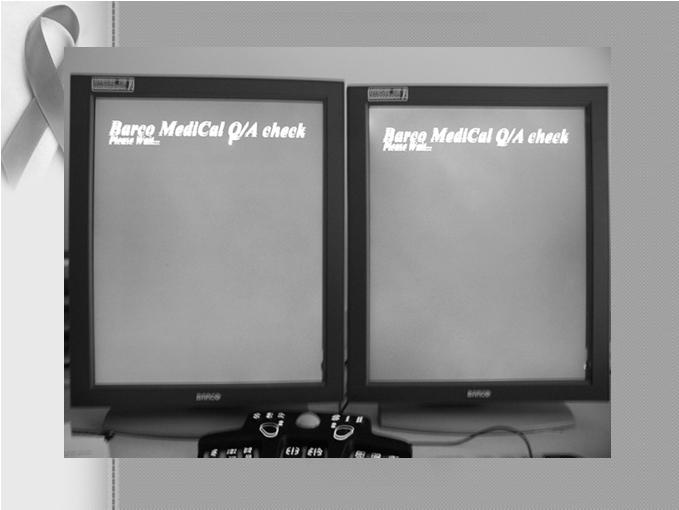
30 Diagnostic Review Workstation Quality Control To assure consistency of the brightness, contrast and image presentation of the radiologist s diagnostic review workstation. Note This diagnostic review workstation Quality Control procedure must be followed only if the workstation manufacturer does not provide an approved Quality Control procedure with their diagnostic review workstation. Frequency Weekly when applicable. Suggested Equipment (Applies to CRT and some LCD displays) Photometer supplied with each diagnostic review workstation Run the display Quality Control software that comes with each diagnostic review workstation.. Measure the display white level for each CRT or LCD display. Measure the display black level for each CRT only display. Measure the DICOM GSDF compliance for each CRT or LCD display. Measure the white level uniformity performance for each CRT display. White Level Performance The operating white level for 5421 LCD display, and 500 cd/m2 for the Barco Nio MDNG-5121 display. The tolerance level for white level performance is ±6%. Done on both monitors at one time. Instructions on screen. Operating levels established during initial calibration by manufacturer. Uses a photometer Computer software analyzes results and indicates if monitors met the pre-programmed control limits. Technologist verifies all tests are completed successfully Internal records for physicist and MQSA inspection 30


31 31


32 Difference in Monitors Dual monitors side by side 5 mega pixel About15 thousand per pair One monitor Many options on set up 10 mega pixel About thousand for one monitor Record Forms Internal logs to the software. Use the Diagnostic Review Workstation Quality Control form in Appendix B to record the results. 32

33 Viewbox and Viewing Conditions Test Checking Monitors for correct Luminance and white levels Frequency: Weekly Objective: To ensure good image review conditions by keeping the view boxes free of dust, finger prints, and other marks and the viewing conditions optimized. Procedure: This test is not unique to digital mammography systems. Follow accepted mammographic QC procedures and action limits to complete this test. Clean viewbox surfaces using window cleaner and soft paper towels. Assure that all marks have been removed. Visually inspect the viewboxes for uniformity of luminance. Assure that all viewbox masking equipment is functioning properly and easily. Visually check the room illumination levels and assure that sources of bright light are not present in the room and are not being reflected from the viewbox surface. Visual Checklist Frequency: Monthly and after any service or maintenance on the mammography system. Objective: To assure that the mammographic x-ray system indicator lights, displays, and mechanical locks and detents are working properly and that the system is mechanically safe. Perform funtiontional test as part of your visual checklist. 33


34 Functional Tests This is part of your monthly Visual checklist. Do this Functional test monthly also At the same time. Functional Test 34

 and the operator Select the Go button to get the")

35 Repeat Analysis Check Frequency: Quarterly. For the repeat rate to be meaningful, an analysis period that yields a patient volume of at least 250 patients or 1,000 exposures is needed. Objective: To determine the number and cause of repeated digital mammograms. Analysis of this data can help identify ways to improve system efficiency and reduce digital retakes and patient exposure. Repeat Analysis Select the Reject Analysis procedure Select the starting date and the ending date then type (reject, repeat or both) and the operator Select the Go button to get the report How is your visual checklist? Action Limit: The overall repeat rate is ideally should be approximately 2 % or less, but a rate of 5% is probably adequate if the radiologist and medical physicist agree. If the total repeat rate changes from the rate determined for the previous analysis period by more than 2.0% of the total exposures included in the analysis, the reasons for the change must be determined. Any corrective actions taken must be recorded and an assessment must be made of their effectiveness. Don t drink and make signs! 35


36 Tomo repeat analysis Combo repeat only counts as one Rejects do not count in repeat rate 36

, and lowering dose Procedure: This test is not unique to digital mammography systems.")
37 Compression Force Test Frequency: Initial installation and semiannually or whenever reduced compression is suspected Objective: To assure that the mammographic system can provide adequate compression in power driven and manual modes and that the equipment does not allow too much compression to be applied. Breast compression is equally important for digital mammography as it is for film screen. It contributes to digital image quality by immobilizing the breast (reduces motion unsharpness), producing a more uniform, thinner tissue (lowers scatter radiation, more even penetration of x-rays, less magnification or geometric blurring, less anatomical superimposition), and lowering dose Procedure: This test is not unique to digital mammography systems. Follow accepted mammographic QC procedures to perform this test. Record the results. Action Limit-Lorad The maximum compression force for the initial power drive must be between 11 and 20 dan (25-45lbs) Upcoming Changes in QC for FFDM New BI-RAD s and lexicon changes New ACR FFDM QC Control Manual New Digital Phantom for FFDM Possibly a new Phantom for DBT 37


38 ACR FFDM QC Manual Project ACR Subcommittee on Quality Assurance Clinical Representatives MITA Representatives ACR Representatives Information written by.et al. Eric Berns, PhD What will be New? Tech Section Enhanced positioning and image quality section New Test: Monitor QC for the Radiologist New Test: Facility QC Review New Format: Corrective Action Log New Documentation: Facility Equipment Inventory Instructions for Mobile Units Eliminating calculations (Yet to be determined) ACR FFDM QC Manual Project The ACR FFDM Phantom 24 X 30 Subcommittee Charge: Design ACR Accreditation Phantom for FFDM Write QC Manual for ACR FFDM Mammography Accreditation Program ACR Digital QC Manual The ACR FFDM Phantom Structure of Manual: Radiologist s Section Clinical Image Quality Section Radiologic Technologist s Section Medical Physicist s Section Educational, Guidance, and Troubleshooting Section Glossary References Index 38

 Minimal training (~ 25,000 Techs")
 Do not need different WW/WL settings")


39 The ACR FFDM Phantom ACR Digital QC Manual Benefits of Phantom Design Provides view of entire detector artifact evaluation W/L optimized for test objects optimizes for artifact eval Finer gradations of test objects Test objects go to smaller sizes AGD measurement & limit same as SFM Meets MQSA Provides single image/exposure for evaluation(s) Minimal training (~ 25,000 Techs currently trained) Provides basis for monitor and laser printer QC ACR Physics Reviewers Can see scores and artifacts on single submitted film (or image) Do not need different WW/WL settings CIRS Model 020 BR3D Mammography Phantom Used on FFDM, Breast Tomo, and Breast CT Internationally Will this be used in U.S.? Design Summary Differences from screen-film phantom Eliminate subtraction for artifacts Add Fail for artifacts Improve specific rules for scoring Change pass/fail criteria from 4,3,3 to 2,3,2 **But, objects are the same (effective) size as SFM phantom Dedicated Breast CT Scanner 39

 slabs made of heterogeneous breast equivalent")

40 Breast CT Scanners John Boone, PhD. has developed a dedicated breast CT scanner at the University of California in It produces 3-D images of the breast to help radiologists detect those hard-to-find tumors. A breast CT scanner has better contrast resolution than mammography. The scanner has an x-ray tube and detector - positioned on opposite sides of a patient. It rotates 360 degrees while sending x-rays through the body at many different angles. National Institute of Biomedical Imaging and Bioengineering (NIBIB CIRS Model 020 BR3D Mammography Phantom The phantom consists of a set of six (6) slabs made of heterogeneous breast equivalent material that exhibits characteristics of real breast tissue and demonstrates how underlying targets can be obscured by varying glandularity. Each slab contains two tissue equivalent materials mimicking 100% adipose and gland tissues swirled together in a approximate 50/50 ratio by weight. One of the slabs contains an assortment of micro-calcifications, fibrils and masses. Dedicated Breast CT Scanner That s enough QC!! Mammo Cats CC view shows 4 mm IDC Coronal view CT shows 12:00 4mm IDC The CIRS Model 020 BR3D Mammography Phantom was designed to assess detectability of various size lesions within a tissue equivalent, complex, heterogeneous background. This phantom provides more realistic challenges for standard screen and FFDM mammography systems as well as Tomosynthesis and breast Computed Tomography. 40
Acceptance Testing of a Digital Breast Tomosynthesis Unit
 Acceptance Testing of a Digital Breast Tomosynthesis Unit 2012 AAPM Spring Clinical Meeting Jessica Clements, M.S., DABR Objectives Review of technology and clinical advantages Acceptance Testing Procedures
Practical Aspects of Medical Physics Surveys of Mammography Equipment and Facilities
 Practical Aspects of Medical Physics Surveys of Mammography Equipment and Facilities Melissa Martin, M.S., FAAPM, FACR, FACMP AAPM Annual Meeting - Philadelphia July 19, 2010 MO-B-204C-1 Educational Objectives
Quality Control of Full Field Digital Mammography Units
 Quality Control of Full Field Digital Mammography Units Melissa C. Martin, M.S., FACMP, FACR, FAAPM Melissa@TherapyPhysics.com 310-612-8127 ACMP Annual Meeting Virginia Beach, VA May 2, 2009 History of
Surveying and QC of Stereotactic Breast Biopsy Units for ACR Accreditation
 Surveying and QC of Stereotactic Breast Biopsy Units for ACR Accreditation AAPM Annual Clinical Meeting Indianapolis, IN August 5, 2013 Learning Objectives Become familiar with the recommendations and
Breast Tomosynthesis. Bob Liu, Ph.D. Department of Radiology Massachusetts General Hospital And Harvard Medical School
 Breast Tomosynthesis Bob Liu, Ph.D. Department of Radiology Massachusetts General Hospital And Harvard Medical School Outline Physics aspects of breast tomosynthesis Quality control of breast tomosynthesis
STEREOTACTIC BREAST BIOPSY EQUIPMENT SURVEYS
 STEREOTACTIC BREAST BIOPSY EQUIPMENT SURVEYS JAMES A. TOMLINSON, M.S. Diagnostic Radiological Physicist American Board of Radiology Certified Medical Physics Consultants, Inc. Bio 28 yrs experience 100%
Quality Control for Stereotactic Breast Biopsy. Robert J. Pizzutiello, Jr., F.A.C.M.P. Upstate Medical Physics, Inc
 Quality Control for Stereotactic Breast Biopsy Robert J. Pizzutiello, Jr., F.A.C.M.P. Upstate Medical Physics, Inc. 716-924-0350 Methods of Imaging Guided Breast Biopsy Ultrasound guided, hand-held needle
Introduction. Digital Mammography QA: Comparing the Manufacturers Recommendations. What is QC and why is it important? Review & compare QC tests
 Slide 1 Digital Mammography QA: Comparing the Manufacturers Recommendations Eric A. Berns, Ph.D. Slide 2 Introduction What is QC and why is it important? Review & compare QC tests Key take home points
THE ART OF THE IMAGE: IDENTIFICATION AND REMEDIATION OF IMAGE ARTIFACTS IN MAMMOGRAPHY
 THE ART OF THE IMAGE: IDENTIFICATION AND REMEDIATION OF IMAGE ARTIFACTS IN MAMMOGRAPHY William Geiser, MS DABR Senior Medical Physicist MD Anderson Cancer Center Houston, Texas wgeiser@mdanderson.org INTRODUCTION
FFDM in the Field: Physicist's Role in the QC of Mammography Laser Printers May Carl R. Keener, Ph.D., DABMP, DABR
 FFDM in the Field: Physicist's Role in the QC of Mammography Laser Printers May 2010 Carl R. Keener, Ph.D., DABMP, DABR keener@marpinc.com MARP Medical & Radiation Physics, Inc. Physicist's Role in the
7/20/2014. Outline. Outline. Disclosures. Learning Objectives. SBB: Practical Aspects of ACR Accreditation, QC and ACR On Site Surveys
 Outline SBB: Practical Aspects of ACR Accreditation, QC and ACR On Site Surveys Robert J. Pizzutiello, MS, FACR, FAAPM, FAC Residency Program Director, Upstate Medical Physics, PC Senior Vice President,
Aspire HD. Program Manual. 2nd Edition - October 2012
 Quality Control 1 Aspire HD Quality Control Program Manual 2nd Edition - October 2012 Overview Installation of FDR Mammography QC Program Weekly Test 2 3 4 Quarterly Test 5 Semi-annual Test 6 Annual Test
Mammography: Physics of Imaging
 Mammography: Physics of Imaging Robert G. Gould, Sc.D. Professor and Vice Chair Department of Radiology and Biomedical Imaging University of California San Francisco, California Mammographic Imaging: Uniqueness
Digital Breast Tomosynthesis
 Digital Breast Tomosynthesis OLIVE PEART MS, RT(R) (M) HTTP://WWW.OPEART.COM 2D Mammography Not 100% effective Limited by tissue superimposition Overlapping tissue can mask tumors False negative Overlapping
MAMMOGRAPHY - HIGH LEVEL TROUBLESHOOTING
 MAMMOGRAPHY - HIGH LEVEL TROUBLESHOOTING Maynard High New York Medical College SS2001-M.High 1 Objectives: Review MQSA and ACR annual QC tests as opportunities for troubleshooting before a significant
8/2/2017. Radiologist Responsibilities. Radiologist Responsibilities. Medical Physicist Mammography Equipment Evaluation and Annual Survey
 Implementation of the 2016 ACR Digital Mammography QC Manual Medical Physicist Mammography Equipment Evaluation and Annual Survey Eric A Berns, PhD, FACR Radiologist Responsibilities Radiologist Responsibilities
Image Quality. HTC Grid High Transmission Cellular Grid provides higher contrast images
 B R E A S T I M A G I N G S O L U T I O N S Setting the benchmark for mammography M-IV Series Innovations in breast imaging The Lorad M-IV Series exemplifies Hologic's commitment to developing advanced
Collimation Assessment Using GAFCHROMIC XR-M2
 Collimation Assessment Using GAFCHROMIC XR-M2 I. Introduction A method of collimation assessment for GE Senographe full-field digital mammography (FFDM) systems is described that uses a self-developing
Image Display and Perception
 Image Display and Perception J. Anthony Seibert, Ph.D. Department of Radiology UC Davis Medical Center Sacramento, California, USA Image acquisition, display, & interpretation X-rays kvp mas Tube filtration
Ansur TNT Users Manual. Plug-In
 Ansur TNT 12000 Plug-In Users Manual August 2009, Rev. 2, 12/09 2009 Fluke Corporation. All rights reserved. Specifications are subject to change without notice. All product names are trademarks of their
Nuclear Associates
 Nuclear Associates 07-647 R/F QC Phantom Operators Manual March 2005 Manual No. 07-647-1 Rev. 2 2004, 2005 Fluke Corporation, All rights reserved. All product names are trademarks of their respective companies
Facility, Unit and Test Equipment Data
 Facility, Unit and Test Equipment Data Medical hysicist's Tests - SAMLE FORMS Facility Information Facility Name Happy Valley Mammography Address Suite 1 Address 1 Oak Street City, State, Zip Anywhere
GE Healthcare. Senographe 2000D Full-field digital mammography system
 GE Healthcare Senographe 2000D Full-field digital mammography system Digital has arrived. The Senographe 2000D Full-Field Digital Mammography (FFDM) system gives you a unique competitive advantage. That
Overview of Safety Code 35
 Common Quality Control Procedures for All s Quality Control Procedures Film All s Daily Quality Control Tests Equipment Warm-up (D1) According to manufacturers instructions Can include auto calibration(d1)
New spectral benefi ts, proven low dose
 New spectral benefi ts, proven low dose Philips MicroDose mammography SI, technical data sheet Philips MicroDose SI with single-shot spectral imaging is a fullfi eld digital mammography solution that delivers
REQUIREMENTS FOR LICENCE HOLDERS WITH RESPECT TO QUALITY CONTROL TESTS FOR DIAGNOSTIC X-RAY IMAGING SYSTEMS
 REQUIREMENTS FOR LICENCE HOLDERS WITH RESPECT TO QUALITY CONTROL TESTS FOR DIAGNOSTIC X-RAY IMAGING SYSTEMS DEPARTMENT OF HEALTH DIRECTORATE: RADIATION CONTROL Implementation date: 31 March 2009 Contents
Image Quality. HTC Grid High Transmission Cellular Grid provides higher contrast images
 B R E A S T I M A G I N G S O L U T I O N S Setting the benchmark for mammography M-IV Series Innovations in breast imaging The Lorad M-IV Series exemplifies Hologic s commitment to developing advanced
ACPSEM Position Paper RECOMMENDATIONS FOR A DIGITAL MAMMOGRAPHY QUALITY ASSURANCE PROGRAM V4.0
 Heggie et al ACPSEM Position Paper: Digital Mammography V4.0 ACPSEM Position Paper RECOMMENDATIONS FOR A DIGITAL MAMMOGRAPHY QUALITY ASSURANCE PROGRAM V4.0 JCP Heggie 1, P Barnes 2, L Cartwright 3, J Diffey
Patient-Assisted Compression Impact on Image Quality and Workflow
 Patient-Assisted Compression Impact on Image Quality and Workflow Senographe Pristina In 2017, GE Healthcare s Senographe Pristina ( Pristina ) was approved by the FDA using the standard technologist-controlled
4.0 How to Turn On the Selenia Dimensions
 Chapter 2 System Controls and Indicators How to Turn On the Selenia Dimensions 4.0 How to Turn On the Selenia Dimensions 4.1 Preparation 1. Reset all three Emergency Off switches. Emergency Off Switches
DISC QC/QA Program for Digital Imaging Systems using the DR Radchex Plus Meter
 DISC QC/QA Program for Digital Imaging Systems using the DR Radchex Plus Meter Revision Date: January 5th, 2017 www.disc-imaging.com Table of Contents Section A: Preliminary Setup Requirements... 4 Tools
Breast Imaging Basics: Module 10 Digital Mammography
 Module 10 Transcript For educational and institutional use. This test bank is licensed for noncommercial, educational inhouse or online educational course use only in educational and corporate institutions.
NJDEP Medical Physicist s Radiographic QC Survey Registration Number:
 Facility Name NJDEP ID # NJDEP Medical Physicist s Radiographic QC Survey PLEASE PRINT Facility Information Unit Information Manufacturer Model Console Model # Console serial # Tube serial # Location (room)
Imaging Technique Optimization of Tungsten Anode FFDM System
 Imaging Technique Optimization of Tungsten Anode FFDM System Biao Chen a*, Andrew P. Smith b, Zhenxue Jing a, Elena Ingal a a Hologic, Inc. 600 Technology Drive, DE 1970 b Hologic, Inc. 35 Crosby Drive,
I. PERFORMANCE OF X-RAY PRODUCTION COMPONENTS FLUOROSCOPIC ACCEPTANCE TESTING: TEST PROCEDURES & PERFORMANCE CRITERIA
 FLUOROSCOPIC ACCEPTANCE TESTING: TEST PROCEDURES & PERFORMANCE CRITERIA EDWARD L. NICKOLOFF DEPARTMENT OF RADIOLOGY COLUMBIA UNIVERSITY NEW YORK, NY ACCEPTANCE TESTING GOALS PRIOR TO 1st CLINICAL USAGE
FFDM -FCRm QC Requirements- What You REALLY Need to Know
 FFDM -FCRm QC Requirements- What You REALLY Need to Know Melissa C. Martin, M.S., FACR, FAAPM, FACMP AAPM Annual Meeting July 28, 2008 FDA Approval for Mammography Fuji FCRm System approved for Mammography
RAD 150 RADIOLOGIC EXPOSURE TECHNIQUE II
 RAD 150 RADIOLOGIC EXPOSURE TECHNIQUE II APPROVED 12/O2/2011 EFFECTIVE SPRING 2013-14 Prefix & Number RAD 150 Course Title: Radiologic Exposure Technique II & Lab Purpose of this submission: New Change/Updated
Mammography Solution. AMULET Innovality. The new leader in the AMULET series. Tomosynthesis, 3D mammography and biopsy are all available.
 Mammography Solution AMULET Innovality The new leader in the AMULET series. Tomosynthesis, 3D mammography and biopsy are all available. FUJIFILM supports the Pink Ribbon Campaign for early detection of
GE Healthcare. Performa. High-performance breast imaging
 GE Healthcare Performa High-performance breast imaging Moving mammography forward. And patients faster. GE Healthcare s unparalleled leadership across mammography begins with a deep understanding of breast
Y11-DR Digital Radiography (DR) Image Quality
 Image Quality") Y11-DR Digital Radiography (DR) Image Quality Image quality is stressed for all systems in Safety Code 35. In the relevant sections Health Canada s advice is the manufacturer s recommended test procedures
Y11-DR Digital Radiography (DR) Image Quality Image quality is stressed for all systems in Safety Code 35. In the relevant sections Health Canada s advice is the manufacturer s recommended test procedures
ADVANCED MEDICAL SYSTEMS PTE LTD Singapore Malaysia India Australia
 Innovative design is combined with cutting-edge technology to yield a definitive diagnosis and never before seen ergonomics GIOTTO CLASS is the result of 25 years of experience in the research and development
Maximizing clinical outcomes
 Maximizing clinical outcomes Digital Tomosynthesis Dual Energy Subtraction Automated Long Length Imaging Improved image quality at a low dose Xray Xray Patented ISS capture technology promotes high sensitivity
DIAGNOSTIC ACCREDITATION PROGRAM. Radiology and CT Quality Control Procedures Workbook
 DIAGNOSTIC ACCREDITATION PROGRAM Radiology and CT Quality Control Procedures Workbook Quality Control Procedures Radiography/CR/DR Safety Code 35 Summary For more detail about each quality control (QC)
Digital Imaging started in the 1972 with Digital subtraction angiography Clinical digital imaging was employed from the 1980 ~ 37 years ago Amount of
 Digital Imaging started in the 1972 with Digital subtraction angiography Clinical digital imaging was employed from the 1980 ~ 37 years ago Amount of radiation to the population due to Medical Imaging
KODAK DIRECTVIEW CR Mammography Feature User s Guide
 KODAK DIRECTVIEW CR Mammography Feature User s Guide 17 September 2010 9G3741 Version 1.0 Carestream Health, Inc. 150 Verona Street Rochester, NY 14608 CARESTREAM, DIRECTVIEW, and DRYVIEW are trademarks
Digital Mammography Quality Control for the Mammographic Technologist
 Ontario Breast Screening Program Digital Mammography Quality Control for the Mammographic Technologist Authors: G.E. Mawdsley, A.K. Bloomquist, M.J. Yaffe October 2011 Revision 3.1 Mammographic Physics
of sufficient quality and quantity
 of sufficient quality and quantity The patient s body attenuates the beam as it passes though the body More energy is deposited in organs located near the entry of the beam than near the exit of the beam
2 nd generation TOMOSYNTHESIS
 2 nd generation TOMOSYNTHESIS 2 nd generation DBT true innovation in breast imaging synthesis graphy Combo mode Stereotactic Biopsy Works in progress: Advanced Technology, simplicity and ergonomics Raffaello
Tomosynthesis and Motion
 Tomosynthesis (3D) Motion Unsharpness Occurs at about the same frequency as conventional mammography (2D) Presents the same issues as 2D motion, EXCEPT that motion may go undetected Most common patient-related
Protocol for the Quality Control of the Physical and Technical Aspects of Digital Breast Tomosynthesis Systems
 Protocol for the Quality Control of the Physical and Technical Aspects of Digital Breast Tomosynthesis Systems Draft version 0.10 February 2013 European Reference Organisation for Quality Assured Breast
Mammography is a radiographic procedure specially designed for detecting breast pathology Approximately 1 woman in 8 will develop breast cancer over
 Mammography is a radiographic procedure specially designed for detecting breast pathology Approximately 1 woman in 8 will develop breast cancer over a lifetime Breast cancer screening programs rely on
Test Equipment for Radiology and CT Quality Control Contents
 Test Equipment for Radiology and CT Quality Control Contents Quality Control Testing...2 Photometers for Digital Clinical Display QC...3 Primary Workstations...3 Secondary Workstations...3 Testing of workstations...3
Performance and care. all in one
 Performance and care all in one INNOVATION IS WHAT DRIVES US THINKING ABOUT THE FUTURE Preventive diagnostics remains an essential weapon in defeating breast cancer. Metaltronica s forward-thinking design
TECHNICAL DATA. GIOTTO IMAGE SDL/W is pre-arranged for Full Field Digital Biopsy examination with the patient in prone position.
 Ver. 01/06/07 TECHNICAL DATA GIOTTO IMAGE SDL/W LOW DOSE, FULL FIELD DIGITAL MAMMOGRAPHY UNIT USING AMORPHOUS SELENIUM (a-se) TECHNOLOGY DETECTOR (pre-arranged for stereotactic biopsy with the same digital
Protocol for the Quality Control of the Physical and Technical Aspects of Digital Breast Tomosynthesis Systems
 Protocol for the Quality Control of the Physical and Technical Aspects of Digital Breast Tomosynthesis Systems Draft version 0.15 January 2014 European Reference Organisation for Quality Assured Breast
Digital radiography (DR) post processing techniques for pediatric radiology
 post processing techniques for pediatric radiology") Digital radiography (DR) post processing techniques for pediatric radiology St Jude Children s Research Hospital Samuel Brady, MS PhD DABR samuel.brady@stjude.org Purpose Review common issues and solutions
Digital radiography (DR) post processing techniques for pediatric radiology St Jude Children s Research Hospital Samuel Brady, MS PhD DABR samuel.brady@stjude.org Purpose Review common issues and solutions
COMPUTED RADIOGRAPHY CHAPTER 4 EFFECTIVE USE OF CR
 This presentation is a professional collaboration of development time prepared by: Rex Christensen Terri Jurkiewicz and Diane Kawamura New Technology https://www.youtube.com/watch?v=ptkzznazb 7U COMPUTED
Digital Mammography Quality Control for the Mammographic Physicist
 Ontario Breast Screening Program Digital Mammography Quality Control for the Mammographic Physicist Authors: G.E. Mawdsley, A.K. Bloomquist, M.J. Yaffe March 2014 Revision 3.2 Mammographic Physics Consulting
1.1.Clinical Artefacts
 1.1.Clinical Artefacts While the incidence of artefact on digital mammographic images 1 is typically less than with film based mammography, artefacts can be produced on digital systems. This section provides
Investigation of the line-pair pattern method for evaluating mammographic focal spot performance
 Investigation of the line-pair pattern method for evaluating mammographic focal spot performance Mitchell M. Goodsitt, a) Heang-Ping Chan, and Bob Liu Department of Radiology, University of Michigan, Ann
Published text: Institute of Cancer Research Repository Please direct all s to:
 This is an author produced version of an article that appears in: MEDICAL PHYSICS The internet address for this paper is: https://publications.icr.ac.uk/1316/ Copyright information: http://www.aip.org/pubservs/web_posting_guidelines.html
Slide 1. Slide 2. Slide 3 ACR CT Accreditation. Multi-Slice CT Artifacts and Quality Control. What are the rules or recommendations for CT QC?
 Slide 1 Multi-Slice CT Artifacts and Quality Control Dianna Cody, Ph.D. Chief, Radiologic Physics UT MD Anderson Cancer Center Houston, TX Slide 2 What are the rules or recommendations for CT QC? AAPM
CR Basics and FAQ. Overview. Historical Perspective
 Page: 1 of 6 CR Basics and FAQ Overview Computed Radiography is a term used to describe a system that electronically records a radiographic image. Computed Radiographic systems use unique image receptors
Nuclear Associates
 Nuclear Associates 07-649 CDRH Fluoroscopic Phantom Users Manual March 2005 Manual No. 07-649-1 Rev. 2 2004, 2005 Fluke Corporation, All rights reserved. Printed in U.S.A. All product names are trademarks
TOPICS: CT Protocol Optimization over the Range of Patient Age & Size and for Different CT Scanner Types: Recommendations & Misconceptions
 CT Protocol Optimization over the Range of Patient Age & Size and for Different CT Scanner Types: Recommendations & Misconceptions TOPICS: Computed Tomography Quick Overview CT Dosimetry Effects of CT
A Practical Overview of the Clinical and Operational Impact of Computed Radiography(CR) Implementations. Shirley Weddle, RT(R)(M), CIIP, BBA
 Implementations. Shirley Weddle, RT(R)(M), CIIP, BBA") A Practical Overview of the Clinical and Operational Impact of Computed Radiography(CR) Implementations Shirley Weddle, RT(R)(M), CIIP, BBA OBJECTIVES Define Computed Radiography (CR) Discuss CR vendor
A Practical Overview of the Clinical and Operational Impact of Computed Radiography(CR) Implementations Shirley Weddle, RT(R)(M), CIIP, BBA OBJECTIVES Define Computed Radiography (CR) Discuss CR vendor
Quality control for digital mammography: Part II recommendations from the ACRIN DMIST trial
 Quality control for digital mammography: Part II recommendations from the ACRIN DMIST trial Martin J. Yaffe, Aili K. Bloomquist, Gordon E. Mawdsley, Etta D. Pisano, R. Edward Hendrick, Laurie L. Fajardo,
diagnostic examination
 RADIOLOGICAL PHYSICS 2011 Raphex diagnostic examination Adel A. Mustafa, Ph.D., Editor PUBLISHED FOR: RAMPS (Radiological and Medical Physics Society of New York) preface The RAPHEX Diagnostic exam 2011
Tomophan TSP004 Manual
 T h e P h a n t o m L a b o r a t o r y 1 Tomophan TSP004 Manual Copyright 2016 WARRANTY THE PHANTOM LABORATORY INCORPORATED ( Seller ) warrants that this product shall remain in good working order and
Ludlum Medical Physics
 Ludlum Medical Physics Medical Imaging Radiology QA Test Tools NEW LUDLUM PRODUCT LINE Medical Physics Products Medical Physics Products What are they? Products used to measure radiation output and to
QC Testing for Computed Tomography (CT) Scanner
 Scanner") QC Testing for Computed Tomography (CT) Scanner QA - Quality Assurance All planned and systematic actions needed to provide confidence on a structure, system or component. all-encompassing program, including
QC Testing for Computed Tomography (CT) Scanner QA - Quality Assurance All planned and systematic actions needed to provide confidence on a structure, system or component. all-encompassing program, including
7/24/2014. Image Quality for the Radiation Oncology Physicist: Review of the Fundamentals and Implementation. Disclosures. Outline
 Image Quality for the Radiation Oncology Physicist: Review of the Fundamentals and Implementation Image Quality Review I: Basics and Image Quality TH-A-16A-1 Thursday 7:30AM - 9:30AM Room: 16A J. Anthony
Nuclear Associates
 Nuclear Associates 07-644 Grid Alignment Test Tool Users Manual March 2005 Manual No. 07-644-1 Rev. 2 2004, 2005 Fluke Corporation, All rights reserved. Printed in U.S.A. All product names are trademarks
GE Healthcare. Essential for life. Senographe Essential Full-Field Digital Mammography system
 GE Healthcare Essential for life Senographe Essential Full-Field Digital Mammography system Excellence in FFDM is a process. An ongoing quest, fueled by our continuing breakthroughs in breast cancer detection
Learning Objectives: What s my motivation? (unknown screen actor) Workshop Overview
 Workshop Overview") Practical Medical Physics Adapting Traditional Clinical Medical Physics to Digital Radiography Charles E. Willis, Ph.D., DABR Associate Professor Department of Imaging Physics The University of Texas M.D.
Practical Medical Physics Adapting Traditional Clinical Medical Physics to Digital Radiography Charles E. Willis, Ph.D., DABR Associate Professor Department of Imaging Physics The University of Texas M.D.
MILADY. Product Data. Page 1 of 8
 Page 1 of 8 The MILADY Mammographic Unit offers the best quality-to-price ratio to our customers worldwide. The unit advanced technology together with the application of industrial production standards,
Essentials of Digital Imaging
 Essentials of Digital Imaging Module 7 Transcript 2016 ASRT. All rights reserved. Essentials of Digital Imaging Module 7 Quality 1. ASRT Animation 2. Welcome Welcome to the Essentials of Digital Imaging:
Features and Weaknesses of Phantoms for CR/DR System Testing
 Physics testing of image detectors Parameters to test Features and Weaknesses of Phantoms for CR/DR System Testing Spatial resolution Contrast resolution Uniformity/geometric distortion Dose response/signal
Outline. Digital Radiography. Understanding Digital Modalities: Image Quality and Dose. Image Quality. Dose Control
 Understanding Digital Modalities: Image Quality and Dose S. Jeff Shepard, M.S. University of Texas M. D. Anderson Cancer Center Houston, Texas Special Acknowledgement: Stephen K. Thompson, M.S. William
Teaching Digital Radiography and Fluoroscopic Radiation Protection
 Teaching Digital Radiography and Fluoroscopic Radiation Protection WCEC 20 th Student Educator Radiographer Conference Dennis Bowman, RT(R), CRT (R)(F) Community Hospital of the Monterey Peninsula (CHOMP)
Automated dose control in multi-slice CT. Nicholas Keat Formerly ImPACT, St George's Hospital, London
 Automated dose control in multi-slice CT Nicholas Keat Formerly ImPACT, St George's Hospital, London Introduction to presentation CT contributes ~50+ % of all medical radiation dose Ideally all patients
3/31/2011. Objectives. Emory University. Historical Development. Historical Development. Historical Development
 Teaching Radiographic Technique in a Digital Imaging Paradigm Objectives 1. Discuss the historical development of digital imaging. Dawn Couch Moore, M.M.Sc., RT(R) Assistant Professor and Director Emory
Digital Radiography : Flat Panel
 Digital Radiography : Flat Panel Flat panels performances & operation How does it work? - what is a sensor? - ideal sensor Flat panels limits and solutions - offset calibration - gain calibration - non
Improved Tomosynthesis Reconstruction using Super-resolution and Iterative Techniques
 Improved Tomosynthesis Reconstruction using Super-resolution and Iterative Techniques Wataru FUKUDA* Junya MORITA* and Masahiko YAMADA* Abstract Tomosynthesis is a three-dimensional imaging technology
Acquisition, Processing and Display
 Acquisition, Processing and Display Terri L. Fauber, R.T. (R)(M) Department of Radiation Sciences School of Allied Health Professions Virginia Commonwealth University Topics Image Characteristics Image
Optimization of Digital Mammography Resolution Using Magnification Technique in Computed Radiography 1
 Optimization of Digital Mammography Resolution Using Magnification Technique in Computed Radiography 1 Gham Hur, M.D., Yoon Joon Hwang, M.D., Soon Joo Cha, M.D., Su Young Kim, M.D., Yong Hoon Kim, M.D.
Disclosures. Outline 7/31/2017. Current Implementation Status of IEC Standard : Exposure Index (EI) for Digital Radiography
 for Digital Radiography") Current Implementation Status of IEC Standard 62494-1: Exposure Index (EI) for Digital Radiography July 31, 2017 Ryan Fisher, PhD, DABR Katie Hulme, MS, DABR None Disclosures Outline Review of IEC Standard
Current Implementation Status of IEC Standard 62494-1: Exposure Index (EI) for Digital Radiography July 31, 2017 Ryan Fisher, PhD, DABR Katie Hulme, MS, DABR None Disclosures Outline Review of IEC Standard
SYLLABUS. TITLE: Equipment Operation I. DEPARTMENT: Radiologic Technology
 CODE: RADT 156 INSTITUTE: Health Science TITLE: Equipment Operation I DEPARTMENT: Radiologic Technology COURSE DESCRIPTION: This course covers the principles of equipment operation and maintenance of radiographic
COST EFFECTIVE FLAT PANEL DIGITAL RADIOGRAPHY UPGRADE SOLUTIONS
 COST EFFECTIVE FLAT PANEL DIGITAL RADIOGRAPHY UPGRADE SOLUTIONS DRive is a digital imaging DR hardware & Software solution designed for General Radiography of anatomy. It intended to replace film/screen
ACR AAPM SIIM Practice Guideline for Determinants of Image Quality in Digital Mammography
 J Digit Imaging (2013) 26:10 25 DOI 10.1007/s10278-012-9521-3 EDITORIAL ACR AAPM SIIM Practice Guideline for Determinants of Image Quality in Digital Mammography Kalpana M. Kanal & Elizabeth Krupinski
GE AMX 4+ Portable X-Ray
 GE AMX 4+ Portable X-Ray Typical Manufacturer s Picture GE Healthcare s AMX-4+ analog X-ray system provides high-performance in a compact, easy-to-maneuver package. The rotating arm and tube simplify positioning
Exposure Indices and Target Values in Radiography: What Are They and How Can You Use Them?
 Exposure Indices and Target Values in Radiography: What Are They and How Can You Use Them? Definition and Validation of Exposure Indices Ingrid Reiser, PhD DABR Department of Radiology University of Chicago
X-ray Imaging. PHYS Lecture. Carlos Vinhais. Departamento de Física Instituto Superior de Engenharia do Porto
 X-ray Imaging PHYS Lecture Carlos Vinhais Departamento de Física Instituto Superior de Engenharia do Porto cav@isep.ipp.pt Overview Projection Radiography Anode Angle Focal Spot Magnification Blurring
Learning Objectives. Outline. Getting Started with CR. Converting the Radiology Department from Film-Screen to Digital: Making the Transition
 Converting the Radiology Department from Film-Screen to Digital: Making the Transition S. Jeff Shepard, MS, DABR University of Texas M. D. Anderson Cancer Center Houston, Texas jshepard@di.mdacc.tmc.edu
PRACTICE GUIDELINE FOR DETERMINANTS OF IMAGE QUALITY IN DIGITAL MAMMOGRAPHY
 The American College of Radiology, with more than 30,000 members, is the principal organization of radiologists, radiation oncologists, and clinical medical physicists in the United States. The College
Beam-Restricting Devices
 Beam-Restricting Devices Three factors contribute to an increase in scatter radiation: Increased kvp Increased Field Size Increased Patient or Body Part Size. X-ray Interactions a some interact with the
Redefining Ergonomics
 Samsung Electronics Co., Ltd. inspires the world and shapes the future with transformative ideas and technologies, redefining the worlds of TVs, smartphones, wearable devices, tablets, cameras, digital
INNOVATION BY DESIGN. Toshiba A History of Leadership REMOTE CONTROL R/F SYSTEM
 INNOVATION BY DESIGN For over 130 years, Toshiba has led the world in developing technology to improve the quality of life. This Made for Life TM commitment is reflected in our family of leading-edge imaging
Mammograph FFDM PRODUCT DATA
 PRODUCT DATA Product data Rev.1 (May 2010) Page Description and Configurations 3 Technical Features 7 Mammography Unit 8 Acquisition Unit 12 Diagnostic Unit (Optional) 12 Size and Dimensions 13 Classifications
MUSICA Nerve Center. Artificial Intelligence. Intelligent tools for your Digital Radiography workflow. Fluoroscopy. Workflow Optimization
 Image Quality Bariatric Abdomen Pediatric Imaging Diagnostic Confidence Fluoroscopy Neonatal Imaging Scatter Suppression Dental Full Leg Full Spine Exposure Control Index Artificial Intelligence General