AERIAL PHOTOGRAPHS CHAPTER 8
|
|
|
- Rafe Higgins
- 6 years ago
- Views:
Transcription
1 CHAPTER 8 AERIAL PHOTOGRAPHS An aerial photograph is any photograph taken from an airborne vehicle (aircraft, drones, balloons) satellites, and so forth). The aerial photograph has many uses in military operations; however, for the purpose of this manual, it will be considered primarily as a map supplement or map substitute COMPARISON WITH MAPS A topographic map may be obsolete because it was compiled many years ago. A recent aerial photograph shows any changes that have taken place since the map was made. For this reason, maps and aerial photographs complement each other. More information can be gained by using the two together than by using either alone. a. Advantages. An aerial photograph has the following advantages over a map: (1) It provides a current pictorial view of the ground that no map can equal. (2) It is more readily obtained. The photograph may be in the hands of the user within a few hours after it is taken; a map may take months to prepare. (3) It may be made for places that are inaccessible to ground soldiers. (4) It shows military features that do not appear on maps. (5) It can provide a day-to-day comparison of selected areas, permitting evaluations to be made of enemy activity. (6) It provides a permanent and objective record of the day-to-day changes with the area. b. Disadvantages. The aerial photograph has the following disadvantages as compared to a map: (1) Ground features are difficult to identify or interpret without symbols and are often obscured by other ground detail as, for example, buildings in wooded areas. (2) Position location and scale are only approximate. (3) Detailed variations in the terrain features are not readily apparent without overlapping photography and a stereoscopic viewing instrument. (4) Because of a lack of contrasting colors and tone, a photograph is difficult to use in poor light. (5) It lacks marginal data. (6) It requires more training to interpret than a map TYPES Aerial photography most commonly used by military personnel may be divided into two mayor types, the vertical and the oblique. Each type depends upon the attitude of the camera with respect to the earth's surface when the photograph is taken. 8-1
 line to the camera axis. The result is coincident with the camera axis.")
2 a. Vertical. A vertical photograph is taken with the camera pointed as straight down as possible (Figures 8-1 and 8-2). Allowable tolerance is usually + 3 from the perpendicular (plumb) line to the camera axis. The result is coincident with the camera axis. A vertical photograph has the following characteristics: (1) The lens axis is perpendicular to the surface of the earth. (2) It covers a relatively small area. (3) The shape of the ground area covered on a single vertical photo closely approximates a square or rectangle. (4) Being a view from above, it gives an unfamiliar view of the ground. (5) Distance and directions may approach the accuracy of maps if taken over flat terrain. (6) Relief is not readily apparent. Figure 8-1. Relationship of the vertical aerial photograph with the ground. Figure 8-2. Vertical photograph. 8-2
 It is used to study an area before an attack, to substitute for a reconnaissance, to substitute for a map, or to supplement a map. A low oblique has the following characteristics: Figure 8-3.")
3 b. Low Oblique. This is a photograph taken with the camera inclined about 30 from the vertical (Figure 8-3 and 8-4.) It is used to study an area before an attack, to substitute for a reconnaissance, to substitute for a map, or to supplement a map. A low oblique has the following characteristics: Figure 8-3. Relationship of low oblique photograph to the ground. (1) It covers a relatively small area. (2) The ground area covered is a trapezoid, although the photo is square or rectangular. (3) The objects have a more familiar view, comparable to viewing from the top of a high hill or tall building. (4) No scale is applicable to the entire photograph, and distance cannot be measured. Parallel lines on the ground are not parallel on this photograph; therefore, direction (azimuth) cannot be measured. (5) Relief is discernible but distorted. (6) It does not show the horizon. Figure 8-4. Low oblique photograph. 8-3

4 c. High Oblique. The high oblique is a photograph taken with the camera inclined about 60 from the vertical (Figures 8-5 and 8-6). It has a limited military application; it is used primarily in the making of aeronautical charts. However, it may be the only photography available. A high oblique has the following characteristics: (1) It covers a very large area (not all usable). (2) The ground area covered is a trapezoid, but the photograph is square or rectangular. (3) The view vanes from the very familiar to unfamiliar, depending on the height at which the photograph is taken. (4) Distances and directions are not measured on this photograph for the same reasons that they are not measured on the low oblique. (5) Relief may be quite discernible but distorted as in any oblique view. The relief is not apparent in a high altitude, high oblique. (6) The horizon is always visible. Figure 8-5. Relationship of high oblique photograph to the ground. Figure 8-6. High oblique photograph. 8-4
5 d. Trimetrogon. This is an assemblage of three photographs taken at the same time, one vertical and two high obliques, in a direction at right angle to the line of flight. The obliques, taken at an angle of 61) from the vertical, sidelap the vertical photography, producing composites from horizon to horizon (Figure 8-7). Figure 8-7. Relationship of cameras to ground for trimetrogon photography (three cameras). e. Multiple Lens Photography. These are composite photographs taken with one camera having two or more lenses, or by two or more cameras. The photographs are combinations of two, four, or eight obliques around a vertical. The obliques are rectified to permit assembly as verticals on a common plane. f. Convergent Photography. These are done with a single twin-lens, wide-angle camera, or with two single-lens, wide-angle cameras coupled rigidly in the same mount so that each camera axis converges when intentionally tilted a prescribed amount (usually 15 or 20 )from the vertical. Again, the cameras are exposed at the same time. For precision mapping, the optical axes of the cameras are parallel to the line of flight, and for reconnaissance photography, the camera axes are at high angles to the line of flight. g. Panoramic. The development and increasing use of panoramic photography in aerial reconnaissance has resulted from the need to cover in greater detail more and more areas of the world. (1) To cover the large areas involved, and to resolve the desired ground detail, present-day reconnaissance systems must operate at extremely high resolution levels. Unfortunately, high-resolution levels and wide-angular coverage are basically contradicting requirements. (2) A panoramic camera is a scanning type of camera that sweeps the terrain of interest from side to side across the direction of flight. This permits the panoramic camera to record a much wider area of ground than either frame or strip cameras. As in the case of the frame cameras, continuous cover is obtained by properly spaced exposures timed to give sufficient overlap between frames. Panoramic cameras are most advantageous for applications requiring the resolution of small ground detail from high altitudes TYPES OF FILM Types of film generally used in aerial photography include panchromatic, infrared, and color. Camouflage detection film is also available. a. Panchromatic. This is the same type of film that is used in the average hand-held small camera. It records 8-5
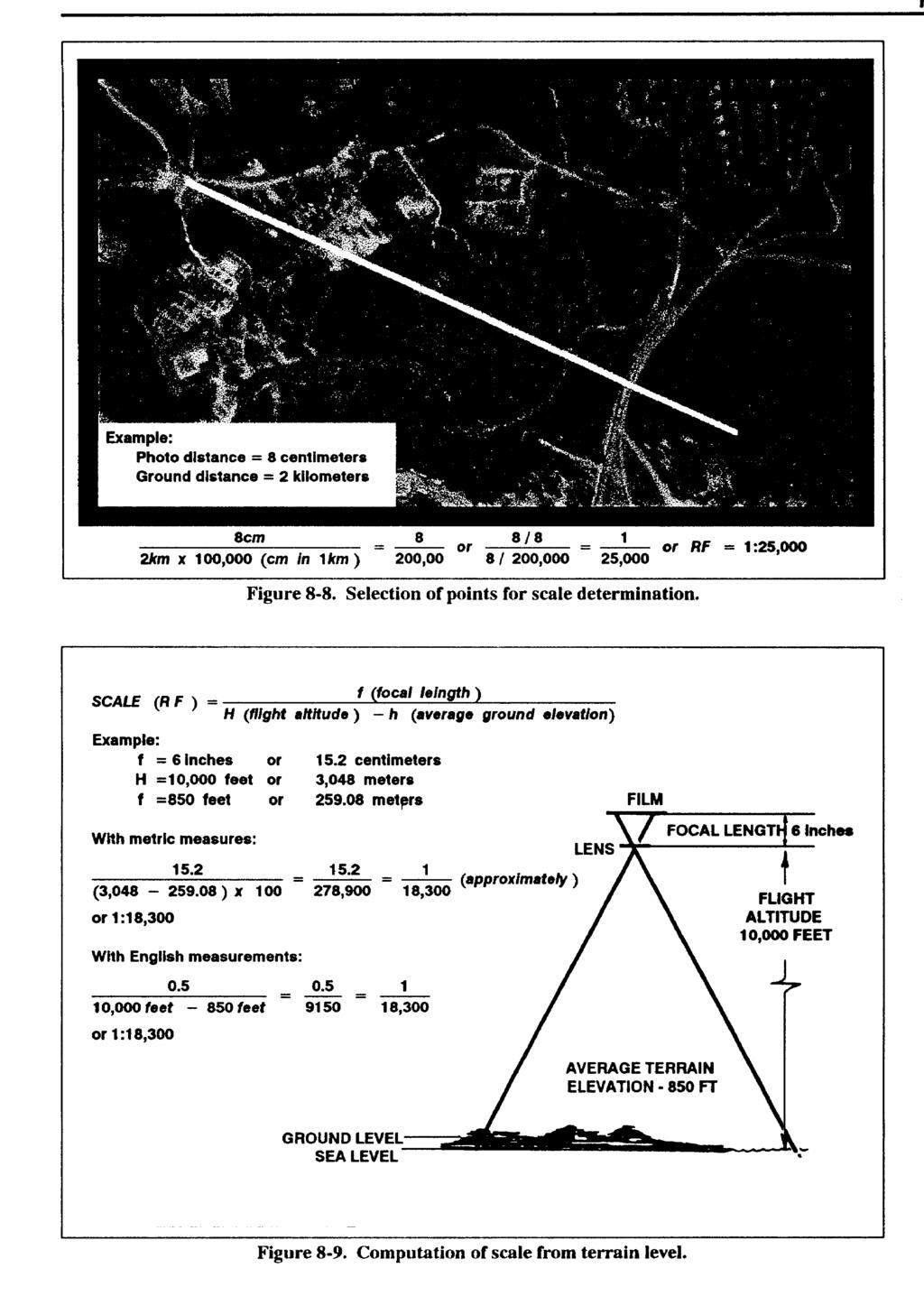
6 the amount of light reflected from objects in tones of gray running from white to black. Most aerial photography is taken with panchromatic film. b. Infrared. This is a black-and-white film that is sensitive to infrared waves. It can be used to detect artificial camouflage materials and to take photographs at night if there is a source of infrared radiation. c. Color. This film is the same as that used in the average hand-held camera. It is limited in its use because of the time required to process it and its need for clear, sunny weather. d. Camouflage Detection. This film is a special type that records natural vegetation in a reddish color. When artificial camouflage materials are photographed, they appear bluish or purplish. The name of this film indicates its primary use NUMBERING AND TITLING INFORMATION Each aerial photograph contains in its margin important information for the photo user. The arrangement, type, and amount of this information is standardized; however, the rapid development of cameras, film, and aeronautical technology since World War II has caused numerous changes in the numbering and titling of aerial photographs. As a result, the photo user may find that the marginal information on older photographs varies somewhat from the standard current practice. With certain camera systems, some of the data are automatically recorded on each exposure, while other systems require that all titling data be added to the film after processing. a. Standard titling data for aerial photography prepared for the use of the Department of Defense are as follows. For reconnaissance and charting photography, items 2 through 14 and item 19 are lettered on the beginning and end of each roll of film. Items 1 through 9 and item 19 are lettered on each exposure. For surveying and mapping photography, items 2 through 19 are lettered on the beginning and end of each roll of film, and items 1, 2, 3, 5, 6, 7, 8, 9, 13, and 19 are lettered on each exposure. (1) Negative number. (2) Camera position. (3) Taking unit. (4) Service. (5) Sortie/mission number. (6) Date (followed by a double hyphen [=]) (7) Time group and zone letter (GMT). (8) Focal length. (9) Altitude. (10) Kind of photography or imagery. (11) Geographic coordinates. (12) Descriptive title. (13) Project number and or name. (14) Camera type and serial number. (15) Cone serial number (if any). (16) Lens type and serial number. (17) Magazine type and serial number. (18) Type of photographic filter used. (19) Security classification. b. Automatically recorded data may differ somewhat in arrangement from the sequence listed above, but the same information is available to the photo user. A detailed explanation of the titling items and the codes used to indicate them may be found in TM SCALE DETERMINATION Before a photograph can be used as a map supplement or substitute, it is necessary to know its scale. On a map, the scale is printed as a representative fraction that expresses the ratio of map distance to ground distance, a. Comparison Method. The scale of a vertical aerial photograph is determined by comparing the meas- MD RF =. On a photograph, the scale is also expressed GD as a ratio, but is the ratio of the photo distance,(pd) to ground distance, RF = PD. The approximate scale GD or average scale (RF) of a vertical aerial photograph is determined by either of two methods; the comparison method or the focal length-flight altitude method. ured distance between two points on the photograph with the measured ground distance between the same two points. The ground distance is determined by actual measurement on the ground or by the use of the scale on a map of SCALE (RF ) = Photo Distance Ground Distance the same area. The points selected on the photograph must be identifiable on the ground or map of the same area and should be spaced in such a manner that a line connecting them will pass through or nearly through the center of the photograph (Figure 8-8). b. Focal Length-Flight Altitude Method. When the marginal information of a photograph includes the focal length and the flight altitude, the scale of the photo is determined using the following formula (Figure 8-9). When the ground elevation is at sea level, H becomes zero, and the formular is as shown in figure 8-10, page
7 8-7
 requires location on the map of the exact point corresponding to each corner of the photo.")
8 Figure Basic computation of scale from sea level INDEXING When aerial photos are taken of an area, it is convenient to have a record of the extent of coverage of each photo. A map on which the area covered by each photo is outlined and numbered or indexed to correspond to the photo is called an index map. There are two methods of preparing index maps. a. The four-corner method (Figures 8-11 and 8-12) requires location on the map of the exact point corresponding to each corner of the photo. If a recognizable object such as a house or road junction can be found exactly at one of the corners, this point may be used on the map as the corner of the photo. If recognizable objects cannot be found at the corners, then the edges of the photo should be outlined on the map by lining up two or more identifiable objects along each edge; the points where the edges intersect should be the exact corners of the photo. If the photo is not a perfect vertical, the area outlined on the map will not be a perfect square or rectangle. After the four sides are drawn on the map, the number of the photograph is written in the enclosed area for identification. This number should be placed in the same corner as it is on the photo. Figure Four-corner method (selection of points). 8-8
 is cut to fit the average area the photos cover on the index map. It is used to outline the individual area covered by each photo.")
9 b. The template method is used when a large number of photos are to be indexed, and the exact area covered by each is not as important as approximate area and location. In this case, a template (cardboard pattern or guide) is cut to fit the average area the photos cover on the index map. It is used to outline the individual area covered by each photo. To construct a template, find the average map dimensions covered by the photos to be indexed as follows. Multiply the average length of the photos by the denominator of the average scale of the photos; multiply this by the scale of the map. Do the same for the width of the photos. This gives the average length and width of the area each photo covers on the map or the size to which the template should be cut (Figure 8-13, page 8-10). Figure Plotting, using the four-corner method. 8-9


10 Figure Constructing a template. c. To index the map, select the general area covered by the first photo and orient the photo to the map. Place the template over the area on the map and adjust it until it covers the area as completely and accurately as possible. Draw lines around the edges of the template. Remove the rectangle and proceed to the next photo (Figure 8-14). Figure Indexing with a template. 8-10

11 d. After all photos have been plotted, write on the map sufficient information to identify the mission or sortie. If more than one sortie is plotted on one map or overlay, use a different color for each sortie. e. In most cases, when a unit orders aerial photography, an index is included to give the basic information. Instead of being annotated on a map of the area, it appears on an overlay and is keyed to a map ORIENTING OF PHOTOGRAPH Orienting the photograph is important because it is of very little value as a map supplement or substitute if its location and direction are not known by the user. a. If a map of the same area as the photograph is available, the photograph is oriented to the map by comparing features common to both and then transferring a direction line from the map to the photograph. b. If no map is available, the shadows on a photograph may be used to get an approximate true-north line. This method is not recommended in the torrid zone (Figure 8-15). (1) North temperate zone. The sun moves from the east in the morning through south at noon to west in the afternoon. Conversely, shadow fall varies from west through north to east. Before noon, therefore, north is to the right of the direction of shadow fall; at noon, north is the direction of shadow fall; and after noon, north is to the left of shadow fall. On an average, the amount of variation in shadow fall per hour is 15 degrees. From marginal information, determine the number of hours from noon that the photo was taken and multiply that number by 15. With a protractor, measure an angle of that amount in the proper direction (right to left) from a clear, distinct shadow, and north is obtained. For photographs taken within three hours of noon, a reasonable accurate north direction can be obtained. Beyond these limits, the 15 must be corrected, depending on time of year and latitude. (2) South temperate zone. The sun moves from east through north at noon to west. Shadows then vary from west through south to east. Before noon, south is to the left of shadow fall; at noon, south is shadow fall; Figure Using shadows on a photograph to find north. 8-11
 Orient the photograph by inspection.")
12 and after noon, south is to the right of shadow fall. Proceed as in (1) above to determine the direction of south. c. On a photograph that can be oriented to the surrounding ground features by inspection, a magnetic north line can be established using a compass. (1) Orient the photograph by inspection. (2) Open the compass and place it on the photograph. (3) Without moving the photograph, rotate the compass until the north arrow is under the stationary black line. (4) Draw a line along the straight edge of the compass. This is a magnetic-north line POINT DESIGNATION GRID Since aerial photographs are seldom exactly the same scale as a map of the same area, it is not feasible to print military grids on them. A special grid is used for the designation of points on photographs (Figure 8-16). This grid, known as the point designation grid, has no relation to the scale of the photo, to any direction, or to the grid used on any other photograph or map. It has only one purpose, to designate points on photographs. a. The point designation grid is rarely printed on photographs; therefore, it becomes the responsibility of each user to construct the grid on the photograph. All users must construct the grid in exactly the same way. Before the grid can be constructed or used, the photograph must be held so that the marginal information, Figure Point designation grid. 8-12
 Draw lines across the photograph joining opposite reference marks at the center of each photograph (fiducial marks).")
13 regardless of where it is located, is in the normal reading position (Figure 8-17, step 1). (1) Draw lines across the photograph joining opposite reference marks at the center of each photograph (fiducial marks). If there are no fiducial marks, the center of each side of the photograph is assumed to be the location of the marks (Figure 8-17, step 2). (2) Space grid lines, starting with the center line, 4 centimeters (1.575 inches) apart (a distance equal to 1,000 meters at a scale of 1:25,000). The 1:25,000 map coordinate scale can be used for this dimension and to accurately designate points on the photograph, but this does not mean that distance can be scaled from the photograph. Extend the grid past the margins of the photograph so that a horizontal and vertical grid line fall outside the picture area (Figure 8-17, step 3). (3) Number each center line "50" and give numerical values to the remaining horizontal and vertical lines so that they increase to the right and up (Figure 8-17, step 4). b. The point designation grid is used, once the photograph is oriented, in the same manner as the grid on a map (Figure 8-18), read right and up. The coordinate scale used with the UTM grid on maps at the scale of Figure Constructing a point designation grid. 8-13

14 1:25,000 may be used to subdivide the grid square in the same manner as on a map. However, because the same point designation grid is used on all photographs, the coordinates of a point on the photograph must be prefixed by the identifying marginal information of the photograph. Figure Reading point designation grid coordinates. 8-14

15 Figure Locating the grid coordinate on a point designation grid. c. A grid coordinate using the point designation grid (Figure 8-19) consists of three parts: (1) The letters "PDG" to indicate an aerial photograph rather than a map grid coordinate. (2)The mission and photo negative number to identify which photograph is being used. (3) The six numerical digits to locate the actual point on the photograph IDENTIFICATION OF PHOTOGRAPH FEATURES The identification of features on a photograph is not difficult if the following facts are remembered. The view that is presented by the aerial photograph is from above and, as a result, objects do not look familiar. Objects that are greatly reduced in size appear distorted. Most aerial photography is black and white, and all colors appear on the photograph in shades of gray. Generally speaking, the darker the natural color, the darker it will appear on the photograph. a. The identification of features on aerial photographs depends upon a careful application of five factors of recognition. No one factor will give a positive identification; it requires the use of all five. (1) Size. The size of unknown objects on a photograph, as determined from the scale of the photograph or a comparison with known objects of known size, gives a clue to their identity. For example, in a built-up area the smaller buildings are usually dwellings, and the larger buildings are commercial or community buildings. (2) Shape (pattern). Many features possess characteristic shapes that readily identify the features. Manmade features appear as straight or smooth curved lines, while natural features usually appear to be irregular. Some of the most prominent man-made features are highways, railroads, bridges, canals, and buildings. Compare the regular shapes of these to the irregular shapes of such natural features as streams and timber lines. (3) Shadows. Shadows are very helpful in identifying features since they show the familiar side view of the object. Some excellent examples are the shadows of water towers or smoke stacks. As viewed directly from above, only a round circle or dot is seen, whereas the shadow shows the profile and helps to identify the object. Relative lengths of shadows also usually give a good indication of relative heights of objects. (4) Shade (tone or texture). Of the many different types of photographic film in use today, the film used for most aerial photography, except for special purposes, is panchromatic film. Panchromatic film is sensitive to all the colors of the spectrum; it registers them as shades of gray, ranging from white to black. This lighter or darker shade of features on aerial photographs is known as the tone. The tone is also dependent on the texture of the features; a paved highway has a smooth texture and produces an even tone on the photograph, while a recently plowed field or a marsh has a rough, choppy texture and results in a rough or grainy tone. It is also important to remember that similar features may have different tones on different photographs, depending on the reflection of sunlight. For example, a river or body of water appears light if it is ref1ecting sunlight directly toward the camera, but appears dark otherwise. Its texture may be smooth or rough, depending on the surface of the water itself. As long as the variables are kept in mind, tone and texture may be used to great advantage. (5) Surrounding objects. Quite often an object not easily recognized by itself may be identified by its 8-15
16 relative position to surrounding objects. Large buildings located beside railroads or railroad sidings are usually factories or warehouses. Schools may be identified by the baseball or football fields. It would be hard to tell the difference between a water tower next to a railroad station and a silo next to a barn, unless the surrounding objects such as the railroad tracks or cultivated fields were considered. b. Before a vertical photograph can be studied or used for identification of features, it must be oriented. This orienting is different from the orienting required for the construction or use of the point designation grid. Orienting for study consists of rotating the photograph so that the shadows on the photograph point toward yourself. You then face a source of light. This places the source of light, an object, and its shadow in a natural relationship. Failure to orient a photograph properly may cause the height or depth of an object to appear reversed. For example, a mine or quarry may appear to be a hill instead of a depression STEREOVISION One of the limitations of the vertical aerial photograph is the lack of apparent relief. Stereoscopic vision (or as it is more commonly known, stereovision or depth perception) is the ability to see three-dimensionally or to see length, width, and depth (distance) at the same time. This requires two views of a single object from two slightly different positions. Most people have the ability to see three-dimensionally. Whenever an object is viewed, it is seen twice once with the left eye and once with the right eye. The fusion or blending together of these two images in the brain permits the judgment of depth or distance. a. In taking aerial photographs, it is rare for only a single picture to be taken. Generally, the aircraft flies over the area to be photographed taking a series of pictures, each of which overlaps the photograph preceding it and the photograph following it so that an unbroken coverage of the area is obtained (Figure 8-20). The amount of overlap is usually 56 percent, which means that 56 percent of the Figure Photographic overlap. 8-16
.")
17 ground detail appearing on one photo also appears on the next photograph. When a single flight does not give the necessary coverage of an area, additional flights must be made. These additional flights are parallel to the first and must have an overlap between them. This overlap between flights is known as side lap and usually is between 15 and 20 percent (Figure 8-21). Figure Side lap. 8-17
18 Figure Pocket stereoscope. Figure Mirror stereoscope. b. The requirement for stereovision can be satisfied by overlapping photographs if one eye sees the object on one photograph and the other eye sees the same object on another photograph. While this can be done after practice with the eyes alone, it is much easier if an optical aid is used. These optical aids are known as stereoscopes. There are many types of stereoscopes, but only the two most commonly used are discussed in this manual. (1) Pocket stereoscope. The pocket stereoscope (Figure 8-22), sometimes known as a lens stereoscope, consists of two magnifying lenses mounted in a metal frame. Because of its simplicity and ease of carrying, it is the type used most frequently by military personnel. (2) Mirror stereoscope. The mirror stereoscope (Figure 8-23) is larger, heavier, and more subject to damage than the pocket stereoscope. It consists of four mirrors mounted in a metal frame. c. A method to orient a pair of aerial photographs for best three-dimensional viewing is outlined below: (1) Arrange the selected pair of photos in such a way that the shadows on them generally appear to fal3 toward the viewer. It is also desirable that the light source during the study of the photography enter the side away from the observer (Figure 8-24). (2) Place the pair of photographs on a flat surface so that the detail on one photograph is directly over the same detail on the other photograph. (3) Place the stereoscope over the photographs so that the left lens is over the left photograph and the right lens is over the right photograph (Figure 8-24). (4) Separate the photographs along the line of flight until a piece of detail appearing in the overlap area of the left photograph is directly under the left lens and the same piece of detail on the right photo is directly under the right lens. (5) With the photograph and stereoscope in this position, a three-dimensional image should be seen. A few minor adjustments may be necessary, such as adjusting the aerial photographs of the stereoscope to obtain the correct position for your eyes. The hills appear to rise and the valleys sink so that 8-18
 The identification of features on photographs is much easier and more accurate with this three-dimensional view.")
19 Figure Placement of stereoscope over stereopair. there is the impression of being in an aircraft looking down at the ground. (6) The identification of features on photographs is much easier and more accurate with this three-dimensional view. The same five factors of recognition (size, shape, shadow, tone, and surrounding objects) must still be applied, but now, with the addition of relief, a more natural view is seen. 8-19
CHAPTER 8 AERIAL PHOTOGRAPHS
 CHAPTER 8 AERIAL PHOTOGRAPHS An aerial photograph is any photograph taken from an airborne vehicle (aircraft, drones, balloons, satellites, and so forth). The aerial photograph has many uses in military
Basics of Photogrammetry Note#6
 Basics of Photogrammetry Note#6 Photogrammetry Art and science of making accurate measurements by means of aerial photography Analog: visual and manual analysis of aerial photographs in hard-copy format
Sample Copy. Not For Distribution.
 Photogrammetry, GIS & Remote Sensing Quick Reference Book i EDUCREATION PUBLISHING Shubham Vihar, Mangla, Bilaspur, Chhattisgarh - 495001 Website: www.educreation.in Copyright, 2017, S.S. Manugula, V.
Volume 1 - Module 6 Geometry of Aerial Photography. I. Classification of Photographs. Vertical
 RSCC Volume 1 Introduction to Photo Interpretation and Photogrammetry Table of Contents Module 1 Module 2 Module 3.1 Module 3.2 Module 4 Module 5 Module 6 Module 7 Module 8 Labs Volume 1 - Module 6 Geometry
not to be republished NCERT Introduction To Aerial Photographs Chapter 6
 Chapter 6 Introduction To Aerial Photographs Figure 6.1 Terrestrial photograph of Mussorrie town of similar features, then we have to place ourselves somewhere in the air. When we do so and look down,
Introduction to Photogeology
 Geological Mapping 1 Academic Year 2016/2017 Introduction to Photogeology Igor Vlahović igor.vlahovic@rgn.hr Today we will say a little about basic photogeological analysis of terrain: about aerial photographs,
PHOTOGRAMMETRY STEREOSCOPY FLIGHT PLANNING PHOTOGRAMMETRIC DEFINITIONS GROUND CONTROL INTRODUCTION
 PHOTOGRAMMETRY STEREOSCOPY FLIGHT PLANNING PHOTOGRAMMETRIC DEFINITIONS GROUND CONTROL INTRODUCTION Before aerial photography and photogrammetry became a reliable mapping tool, planimetric and topographic
Land Navigation / Map Reading
 Land Navigation / Map Reading What is the Field Manual for map reading and land navigation? FM 3-25.26 What are the basic colors of a map, and what does each color represent? Black - Indicates cultural
Geometry of Aerial Photographs
 Geometry of Aerial Photographs Aerial Cameras Aerial cameras must be (details in lectures): Geometrically stable Have fast and efficient shutters Have high geometric and optical quality lenses They can
NREM 345 Week 2, Material covered this week contributes to the accomplishment of the following course goal:
 NREM 345 Week 2, 2010 Reading assignment: Chapter. 4 and Sec. 5.1 to 5.2.4 Material covered this week contributes to the accomplishment of the following course goal: Goal 1: Develop the understanding and
CHAPTER 3 MARGINAL INFORMATION AND SYMBOLS
 CHAPTER 3 MARGINAL INFORMATION AND SYMBOLS A map could be compared to any piece of equipment, in that before it is placed into operation the user must read the instructions. It is important that you, as
11/25/2009 CHAPTER THREE INTRODUCTION INTRODUCTION (CONT D) THE AERIAL CAMERA: LENS PHOTOGRAPHIC SENSORS
 THE AERIAL CAMERA: LENS PHOTOGRAPHIC SENSORS") INTRODUCTION CHAPTER THREE IC SENSORS Photography means to write with light Today s meaning is often expanded to include radiation just outside the visible spectrum, i. e. ultraviolet and near infrared
INTRODUCTION CHAPTER THREE IC SENSORS Photography means to write with light Today s meaning is often expanded to include radiation just outside the visible spectrum, i. e. ultraviolet and near infrared
Following are the geometrical elements of the aerial photographs:
 Geometrical elements/characteristics of aerial photograph: An aerial photograph is a central or perspective projection, where the bundles of perspective rays meet at a point of origin called perspective
Photo Scale The photo scale and representative fraction may be calculated as follows: PS = f / H Variables: PS - Photo Scale, f - camera focal
 Scale Scale is the ratio of a distance on an aerial photograph to that same distance on the ground in the real world. It can be expressed in unit equivalents like 1 inch = 1,000 feet (or 12,000 inches)
CHAPTER 5. Image Interpretation
 CHAPTER 5 Image Interpretation Introduction To translate images into information, we must apply a specialized knowlage, image interpretation, which we can apply to derive useful information from the raw
UNITED STATES MARINE CORPS FIELD MEDICAL TRAINING BATTALION Camp Lejeune, NC
 UNITED STATES MARINE CORPS FIELD MEDICAL TRAINING BATTALION Camp Lejeune, NC 28542-0042 FMST 206 Land Navigation TERMINAL LEARNING OBJECTIVE 1. Given a military topographic map, protractor, and objective,
Exploring the Earth with Remote Sensing: Tucson
 Exploring the Earth with Remote Sensing: Tucson Project ASTRO Chile March 2006 1. Introduction In this laboratory you will explore Tucson and its surroundings with remote sensing. Remote sensing is the
Photogrammetry. Lecture 4 September 7, 2005
 Photogrammetry Lecture 4 September 7, 2005 What is Photogrammetry Photogrammetry is the art and science of making accurate measurements by means of aerial photography: Analog photogrammetry (using films:
Acquisition of Aerial Photographs and/or Satellite Imagery
 Acquisition of Aerial Photographs and/or Satellite Imagery Acquisition of Aerial Photographs and/or Imagery From time to time there is considerable interest in the purchase of special-purpose photography
Lesson 12. Stereoscopy and Photo Preparation. Steven J. Steinberg
 Lesson 12 Stereoscopy and Photo Preparation Steven J. Steinberg Description: The lessons in this section focus on stereoscopy and photo preparation. We begin with a discussion of the principles of stereoscopy.
Acquisition of Aerial Photographs and/or Imagery
 Acquisition of Aerial Photographs and/or Imagery Acquisition of Aerial Photographs and/or Imagery From time to time there is considerable interest in the purchase of special-purpose photography contracted
Copyrighted Material. Copyrighted Material. Copyrighted. Copyrighted. Material
 Engineering Graphics ORTHOGRAPHIC PROJECTION People who work with drawings develop the ability to look at lines on paper or on a computer screen and "see" the shapes of the objects the lines represent.
Important Questions. Surveying Unit-II. Surveying & Leveling. Syllabus
 Surveying Unit-II Important Questions Define Surveying and Leveling Differentiate between Surveying and Leveling. Explain fundamental Principles of Surveying. Explain Plain and Diagonal Scale. What is
The Elements and Principles of Design. The Building Blocks of Art
 The Elements and Principles of Design The Building Blocks of Art 1 Line An element of art that is used to define shape, contours, and outlines, also to suggest mass and volume. It may be a continuous mark
UNIT 5a STANDARD ORTHOGRAPHIC VIEW DRAWINGS
 UNIT 5a STANDARD ORTHOGRAPHIC VIEW DRAWINGS 5.1 Introduction Orthographic views are 2D images of a 3D object obtained by viewing it from different orthogonal directions. Six principal views are possible
Isometric Drawing Chapter 26
 Isometric Drawing Chapter 26 Sacramento City College EDT 310 EDT 310 - Chapter 26 - Isometric Drawing 1 Drawing Types Pictorial Drawing types: Perspective Orthographic Isometric Oblique Pictorial - like
10.2 Images Formed by Lenses SUMMARY. Refraction in Lenses. Section 10.1 Questions
 10.2 SUMMARY Refraction in Lenses Converging lenses bring parallel rays together after they are refracted. Diverging lenses cause parallel rays to move apart after they are refracted. Rays are refracted
High Resolution Sensor Test Comparison with SPOT, KFA1000, KVR1000, IRS-1C and DPA in Lower Saxony
 High Resolution Sensor Test Comparison with SPOT, KFA1000, KVR1000, IRS-1C and DPA in Lower Saxony K. Jacobsen, G. Konecny, H. Wegmann Abstract The Institute for Photogrammetry and Engineering Surveys
SS 0507 PRINCIPLES OF PHOTOGRAPHY
 SUBCOURSE SS 0507 PRINCIPLES OF PHOTOGRAPHY EDITION 6 Lesson 4/Learning Event 1 LESSON 4 APPLY THE BASICS OF COMPOSITION TASK Define and state the theory and application of composing the elements of a
EXAMPLES OF TOPOGRAPHIC MAPS PRODUCED FROM SPACE AND ACHIEVED ACCURACY CARAVAN Workshop on Mapping from Space, Phnom Penh, June 2000
 EXAMPLES OF TOPOGRAPHIC MAPS PRODUCED FROM SPACE AND ACHIEVED ACCURACY CARAVAN Workshop on Mapping from Space, Phnom Penh, June 2000 Jacobsen, Karsten University of Hannover Email: karsten@ipi.uni-hannover.de
Photographic Interpretation Handbook, United States Forces: Section 09 Height and Depth Finding from Parallax
 University of Nebraska - Lincoln DigitalCommons@University of Nebraska - Lincoln DOD Military Intelligence U.S. Department of Defense 4-1944 Photographic Interpretation Handbook, United States Forces:
COPYRIGHTED MATERIAL. Overview
 In normal experience, our eyes are constantly in motion, roving over and around objects and through ever-changing environments. Through this constant scanning, we build up experience data, which is manipulated
Aerial Photo Interpretation
 Aerial Photo Interpretation Aerial Photo Interpretation To date, course has focused on skills of photogrammetry Scale Distance Direction Area Height There s another side to Aerial Photography: Interpretation
Lesson 4: Photogrammetry
 This work by the National Information Security and Geospatial Technologies Consortium (NISGTC), and except where otherwise Development was funded by the Department of Labor (DOL) Trade Adjustment Assistance
COPYRIGHTED MATERIAL OVERVIEW 1
 OVERVIEW 1 In normal experience, our eyes are constantly in motion, roving over and around objects and through ever-changing environments. Through this constant scanning, we build up experiential data,
Introduction to Aerial Photographs and Topographic maps (Chapter 3)
") GEOLOGY 306 Laboratory Instructor: TERRY J. BOROUGHS NAME: Introduction to Aerial Photographs and Topographic maps (Chapter 3) For this assignment you will require: a calculator and metric ruler. Objectives:
GEOLOGY 306 Laboratory Instructor: TERRY J. BOROUGHS NAME: Introduction to Aerial Photographs and Topographic maps (Chapter 3) For this assignment you will require: a calculator and metric ruler. Objectives:
Surveying & Measurement. Detail Survey Topographic Surveying
 Surveying & Measurement Detail Survey Topographic Surveying Introduction Mapping surveys are made to determine the relief of the earth s surface and locate critical points on it. to determine the locations
Mapping The Study Area
 While on the beach you will need to take some measurements to show where the study area is relative to the rest of the world and to show what is inside the study area. Once the measurements have been taken,
MONITORING RUBBLE-MOUND COASTAL STRUCTURES WITH PHOTOGRAMMETRY
 ,. CETN-III-21 2/84 MONITORING RUBBLE-MOUND COASTAL STRUCTURES WITH PHOTOGRAMMETRY INTRODUCTION: Monitoring coastal projects usually involves repeated surveys of coastal structures and/or beach profiles.
Introduction to Remote Sensing
 Introduction to Remote Sensing 1 Outline Remote Sensing Defined Electromagnetic Energy (EMR) Resolution Interpretation 2 Remote Sensing Defined Remote Sensing is: The art and science of obtaining information
Suveying Lectures for CE 498
 Suveying Lectures for CE 498 SURVEYING CLASSIFICATIONS Surveying work can be classified as follows: 1- Preliminary Surveying In this surveying the detailed data are collected by determining its locations
COPYRIGHTED MATERIAL. Contours and Form DEFINITION
 1 DEFINITION A clear understanding of what a contour represents is fundamental to the grading process. Technically defined, a contour is an imaginary line that connects all points of equal elevation above
elements of design worksheet
 elements of design worksheet Line Line: An element of art that is used to define shape, contours, and outlines, also to suggest mass and volume. It may be a continuous mark made on a surface with a pointed
MINNESOTA DEPARTMENT OF TRANSPORTATION OFFICE OF LAND MANAGEMENT SURVEYING AND MAPPING SECTION PHOTOGRAMMETRY UNIT
 SEP. 2011 MINNESOTA DEPARTMENT OF TRANSPORTATION OFFICE OF LAND MANAGEMENT SURVEYING AND MAPPING SECTION PHOTOGRAMMETRY UNIT SPECIAL PROVISIONS FOR: GROUP 1: AERIAL PHOTOGRAPHY/PHOTOGRAMMETRIC LAB SERVICES
Outline Remote Sensing Defined Resolution Electromagnetic Energy (EMR) Types Interpretation Applications
 Types Interpretation Applications") Introduction to Remote Sensing Outline Remote Sensing Defined Resolution Electromagnetic Energy (EMR) Types Interpretation Applications Remote Sensing Defined Remote Sensing is: The art and science of
Introduction to Remote Sensing Outline Remote Sensing Defined Resolution Electromagnetic Energy (EMR) Types Interpretation Applications Remote Sensing Defined Remote Sensing is: The art and science of
Photo Grid Analysis. Concept
 Photo Grid Analysis Concept Changes in vegetation, soil, fuel loading, streambanks, or other photographed items can be monitored by outlining the items on a clear plastic sheet that is then placed over
Outline Remote Sensing Defined Resolution Electromagnetic Energy (EMR) Types Interpretation Applications 2
 Types Interpretation Applications 2") Introduction to Remote Sensing 1 Outline Remote Sensing Defined Resolution Electromagnetic Energy (EMR) Types Interpretation Applications 2 Remote Sensing Defined Remote Sensing is: The art and science
Introduction to Remote Sensing 1 Outline Remote Sensing Defined Resolution Electromagnetic Energy (EMR) Types Interpretation Applications 2 Remote Sensing Defined Remote Sensing is: The art and science
Line Line Characteristic of Line are: Width Length Direction Focus Feeling Types of Line: Outlines Contour Lines Gesture Lines Sketch Lines
 Line Line: An element of art that is used to define shape, contours, and outlines, also to suggest mass and volume. It may be a continuous mark made on a surface with a pointed tool or implied by the edges
Target Range Analysis for the LOFTI Triple Field-of-View Camera
 Critical Imaging LLC Tele: 315.732.1544 2306 Bleecker St. www.criticalimaging.net Utica, NY 13501 info@criticalimaging.net Introduction Target Range Analysis for the LOFTI Triple Field-of-View Camera The
ORTHOGRAPHIC PROJECTION
 ORTHOGRAPHIC PROJECTION C H A P T E R S I X OBJECTIVES 1. Recognize and the symbol for third-angle projection. 2. List the six principal views of projection. 3. Understand which views show depth in a drawing
Student Name: Teacher: Date: District: Rowan. Assessment: 9_12 T and I IC61 - Drafting I Test 1. Description: Unit C - Sketching - Test 2.
 Student Name: Teacher: Date: District: Rowan Assessment: 9_12 T and I IC61 - Drafting I Test 1 Description: Unit C - Sketching - Test 2 Form: 501 1. The most often used combination of views includes the:
COMPARISON OF INFORMATION CONTENTS OF HIGH RESOLUTION SPACE IMAGES
 COMPARISON OF INFORMATION CONTENTS OF HIGH RESOLUTION SPACE IMAGES H. Topan*, G. Büyüksalih*, K. Jacobsen ** * Karaelmas University Zonguldak, Turkey ** University of Hannover, Germany htopan@karaelmas.edu.tr,
This histogram represents the +½ stop exposure from the bracket illustrated on the first page.
 Washtenaw Community College Digital M edia Arts Photo http://courses.wccnet.edu/~donw Don W erthm ann GM300BB 973-3586 donw@wccnet.edu Exposure Strategies for Digital Capture Regardless of the media choice
2019 NYSAPLS Conf> Fundamentals of Photogrammetry for Land Surveyors
 2019 NYSAPLS Conf> Fundamentals of Photogrammetry for Land Surveyors George Southard GSKS Associates LLC Introduction George Southard: Master s Degree in Photogrammetry and Cartography 40 years working
BACKGROUND INFORMATION
 Build an Island INTRODUCTION For this assignment, you will be creating a topographic map and three-dimensional model of a fictional island that you have designed. You will start by exploring some basic
TECHNICAL INFORMATION Traffic Template Catalog No. TT1
 Copyright 2016 by SIRCHIE All Rights Reserved. TECHNICAL INFORMATION Traffic Template Catalog No. TT1 INTRODUCTION Your SIRCHIE Traffic Template is a versatile police tool designed to make even the most
Name: Period: THE ELEMENTS OF ART
 Name: Period: THE ELEMENTS OF ART Name: Period: An element of art that is used to define shape, contours, and outlines, also to suggest mass and volume. It may be a continuous mark made on a surface with
Module 4, Investigation 2: Log 1 What features do archaeologists look for on an image?
 What are the seven elements used by geoarchaeologists to analyze and interpret remotely sensed images? Geoarchaeologists face several issues when using remotely sensed images. They must determine the location
technical drawing
 technical drawing school of art, design and architecture nust spring 2011 http://www.youtube.com/watch?v=q6mk9hpxwvo http://www.youtube.com/watch?v=bnu2gb7w4qs Objective abstraction - axonometric view
.VP CREATING AN INVENTED ONE POINT PERSPECTIVE SPACE
 PAGE ONE Organize an invented 1 point perspective drawing in the following order: 1 Establish an eye level 2 Establish a Center Line Vision eye level vision Remember that the vanishing point () in one
LAB 2: AERIAL PHOTOGRAPHY AND PHOTOGRAMMETRY PART 1: INTERPRETATION OF AERIAL PHOTOGRAPHY
 E&ES 328 Remote Sensing Laboratory LAB 2: AERIAL PHOTOGRAPHY AND PHOTOGRAMMETRY Due February 22, 2012 PART 1: INTERPRETATION OF AERIAL PHOTOGRAPHY Some of the first aerial photography, employed during
MSB Imagery Program FAQ v1
 MSB Imagery Program FAQ v1 (F)requently (A)sked (Q)uestions 9/22/2016 This document is intended to answer commonly asked questions related to the MSB Recurring Aerial Imagery Program. Table of Contents
11/12/2015 CHAPTER 7. Axonometric Drawings (cont.) Axonometric Drawings (cont.) Isometric Projections (cont.) 1) Axonometric Drawings
 Axonometric Drawings (cont.) Isometric Projections (cont.) 1) Axonometric Drawings") CHAPTER 7 1) Axonometric Drawings 1) Introduction Isometric & Oblique Projection Axonometric projection is a parallel projection technique used to create a pictorial drawing of an object by rotating the
CHAPTER 7 1) Axonometric Drawings 1) Introduction Isometric & Oblique Projection Axonometric projection is a parallel projection technique used to create a pictorial drawing of an object by rotating the
Introduction to Aerial Photographs and Topographic maps (Chapter 7, 9 th edition) or (chapter 3, 8 th edition)
 or (chapter 3, 8 th edition)") GEOLOGY 306 Laboratory Instructor: TERRY J. BOROUGHS NAME: Introduction to Aerial Photographs and Topographic maps (Chapter 7, 9 th edition) or (chapter 3, 8 th edition) For this assignment you will require:
GEOLOGY 306 Laboratory Instructor: TERRY J. BOROUGHS NAME: Introduction to Aerial Photographs and Topographic maps (Chapter 7, 9 th edition) or (chapter 3, 8 th edition) For this assignment you will require:
FOR 474: Forest Inventory. FOR 474: Forest Inventory. Why do we Care About Forest Sampling?
 FOR 474: Forest Inventory 1. Advanced Forest Inventory The Need for Forest Sampling Brief Intro to Remote Sensing and GIS Readings: FOR 474: Forest Inventory Related Courses! FOR 274: Forest Measurements
Century focus and test chart instructions
 Century focus and test chart instructions INTENTIONALLY LEFT BLANK Page 2 Table of Contents TABLE OF CONTENTS Introduction Page 4 System Contents Page 4 Resolution: A note from Schneider Optics Page 6
Black Dot shows actual Point location
 207 Plate 1 Use of scanned archive aerial photographs, digital photogrammetry and GIS to plot river channel erosion along the Afon Trannon, Wales (part of the study by Mount et al 2000, 2003). Plate 2
Relief Displacement of Vertical Features
 G 210 Lab. Relief Displacement of Vertical Features An increase in the elevation of a feature causes its position on the photograph to be displaced radially outward from the principle point. Hence, when
Content Reviewer (CR) Swati Katiyar Senior Research Fellow, Birla Institute of Scientific Research, Jaipur Language Editor (LE)
 Swati Katiyar Senior Research Fellow, Birla Institute of Scientific Research, Jaipur Language Editor (LE)") Component-I(A) - Personal Details Role Name Affiliation Principal Investigator Prof.MasoodAhsanSiddiqui Department of Geography, JamiaMilliaIslamia, New Delhi Paper Coordinator, if any Dr. M P Punia Head,
Component-I(A) - Personal Details Role Name Affiliation Principal Investigator Prof.MasoodAhsanSiddiqui Department of Geography, JamiaMilliaIslamia, New Delhi Paper Coordinator, if any Dr. M P Punia Head,
Radar Imagery for Forest Cover Mapping
 Purdue University Purdue e-pubs LARS Symposia Laboratory for Applications of Remote Sensing 1-1-1981 Radar magery for Forest Cover Mapping D. J. Knowlton R. M. Hoffer Follow this and additional works at:
Multi-View Drawing Review
 Multi-View Drawing Review Sacramento City College EDT 300/ENGR 306 EDT 300 / ENGR 306 - Chapter 5 1 Objectives Identify and select the various views of an object. Determine the number of views needed to
Lab #4 Topographic Maps and Aerial Photographs
 Lab #4 Topographic Maps and Aerial Photographs Purpose To familiarize you with using topographic maps. Visualizing the shape of landforms from topographic maps is an essential skill in geology. Proficiency
Abstract Quickbird Vs Aerial photos in identifying man-made objects
 Abstract Quickbird Vs Aerial s in identifying man-made objects Abdullah Mah abdullah.mah@aramco.com Remote Sensing Group, emap Division Integrated Solutions Services Department (ISSD) Saudi Aramco, Dhahran
Geometric Dimensioning and Tolerancing
 Geometric dimensioning and tolerancing (GDT) is Geometric Dimensioning and Tolerancing o a method of defining parts based on how they function, using standard ASME/ANSI symbols; o a system of specifying
Atmospheric interactions; Aerial Photography; Imaging systems; Intro to Spectroscopy Week #3: September 12, 2018
 GEOL 1460/2461 Ramsey Introduction/Advanced Remote Sensing Fall, 2018 Atmospheric interactions; Aerial Photography; Imaging systems; Intro to Spectroscopy Week #3: September 12, 2018 I. Quick Review from
CAMERA BASICS. Stops of light
 CAMERA BASICS Stops of light A stop of light isn t a quantifiable measurement it s a relative measurement. A stop of light is defined as a doubling or halving of any quantity of light. The word stop is
Appendix III Graphs in the Introductory Physics Laboratory
 Appendix III Graphs in the Introductory Physics Laboratory 1. Introduction One of the purposes of the introductory physics laboratory is to train the student in the presentation and analysis of experimental
CHAPTER. Line and Shape
 CHAPTER 4 Line and Shape Lines are everywhere in the real world. For example, doorways have two vertical lines, and a volleyball has one curved line. The real world is also full of shapes. A door is a
Beginning Engineering Graphics 3 rd Week Lecture Notes Instructor: Edward N. Locke Topic: The Coordinate System, Types of Drawings and Orthographic
 Beginning Engineering Graphics 3 rd Week Lecture Notes Instructor: Edward N. Locke Topic: The Coordinate System, Types of Drawings and Orthographic 1 st Subject: The Cartesian Coordinate System The Cartesian
Chapter 2 Threat FM 20-3
 Chapter 2 Threat The enemy uses a variety of sensors to detect and identify US soldiers, equipment, and supporting installations. These sensors use visual, ultraviolet (W), infared (IR), radar, acoustic,
Drawing Goats. Proceedings of the 28th Annual Goat Field Day, Langston University, April 27, 2013
 Drawing Goats Mr. Kenneth Williams Science Illustrator Science Graphics and Design Drawing goats or any other subject depends on accurate observation and correct proportional placement of shapes and lines.
Chapter 3: Assorted notions: navigational plots, and the measurement of areas and non-linear distances
 : navigational plots, and the measurement of areas and non-linear distances Introduction Before we leave the basic elements of maps to explore other topics it will be useful to consider briefly two further
Large Scale Photogrammetric Maps for Land Planning
 Large Scale Photogrammetric Maps for Land Planning A lva F. W arren Clyde E. Williams & Associates, Inc. South Bend, Indiana Introduction It is my purpose to give a brief explanation of the method of making
746A27 Remote Sensing and GIS
 746A27 Remote Sensing and GIS Lecture 1 Concepts of remote sensing and Basic principle of Photogrammetry Chandan Roy Guest Lecturer Department of Computer and Information Science Linköping University What
VERTICAL AERIAL PHOTOGRAPHY
 VERTICAL AERIAL PHOTOGRAPHY Mike Craig Cooperative Research Centre for Landscape Environments and Mineral Exploration, Geoscience Australia. PO Box 378, Canberra, ACT 2601. E-mail: mike.craig@ga.gov.au
KODAK VISION Expression 500T Color Negative Film / 5284, 7284
 TECHNICAL INFORMATION DATA SHEET TI2556 Issued 01-01 Copyright, Eastman Kodak Company, 2000 1) Description is a high-speed tungsten-balanced color negative camera film with color saturation and low contrast
Image interpretation I and II
 Image interpretation I and II Looking at satellite image, identifying different objects, according to scale and associated information and to communicate this information to others is what we call as IMAGE
Lecture # 7 Coordinate systems and georeferencing
 Lecture # 7 Coordinate systems and georeferencing Coordinate Systems Coordinate reference on a plane Coordinate reference on a sphere Coordinate reference on a plane Coordinates are a convenient way of
Civil Engineering Drawing
 Civil Engineering Drawing Third Angle Projection In third angle projection, front view is always drawn at the bottom, top view just above the front view, and end view, is drawn on that side of the front
An Introduction to Geomatics. Prepared by: Dr. Maher A. El-Hallaq خاص بطلبة مساق مقدمة في علم. Associate Professor of Surveying IUG
 An Introduction to Geomatics خاص بطلبة مساق مقدمة في علم الجيوماتكس Prepared by: Dr. Maher A. El-Hallaq Associate Professor of Surveying IUG 1 Airborne Imagery Dr. Maher A. El-Hallaq Associate Professor
Chapter 6 Navigation and Field Mapping
 Chapter 6 Navigation and Field Mapping In this chapter you will learn about: Orienting maps Measuring a bearing on a map Plotting points on a map using latitude/longitude Plotting points on a map using
Remote Sensing Platforms
 Types of Platforms Lighter-than-air Remote Sensing Platforms Free floating balloons Restricted by atmospheric conditions Used to acquire meteorological/atmospheric data Blimps/dirigibles Major role - news
Engineering Graphics, Class 8 Orthographic Projection. Mohammad I. Kilani. Mechanical Engineering Department University of Jordan
 Engineering Graphics, Class 8 Orthographic Projection Mohammad I. Kilani Mechanical Engineering Department University of Jordan Multi view drawings Multi view drawings provide accurate shape descriptions
Chapters 1 & 2. Definitions and applications Conceptual basis of photogrammetric processing
 Chapters 1 & 2 Chapter 1: Photogrammetry Definitions and applications Conceptual basis of photogrammetric processing Transition from two-dimensional imagery to three-dimensional information Automation
Light and Applications of Optics
 UNIT 4 Light and Applications of Optics Topic 4.1: What is light and how is it produced? Topic 4.6: What are lenses and what are some of their applications? Topic 4.2 : How does light interact with objects
Problem of the Month: Between the Lines
 Problem of the Month: Between the Lines Overview: In the Problem of the Month Between the Lines, students use polygons to solve problems involving area. The mathematical topics that underlie this POM are
The Putora Sharpness Indicator Instructions
 264 Morris Avenue Mountain Lakes, NJ 07046 973-335-4460 The Professionals Choice sales@zgc.com www.zgc.com About the Sharpness Indicator. The Putora Sharpness Indicator Instructions Description The Sharpness
Teacher s Resource. 2. The student will see the images reversed left to right.
 Teacher s Resource Answer Booklet Reflection of Light With a Plane (Flat) Mirror Trace a Star Page 16 1. The individual students will complete the activity with varying degrees of difficulty. 2. The student
Panoramic imaging. Ixyzϕθλt. 45 degrees FOV (normal view)
") Camera projections Recall the plenoptic function: Panoramic imaging Ixyzϕθλt (,,,,,, ) At any point xyz,, in space, there is a full sphere of possible incidence directions ϕ, θ, covered by 0 ϕ 2π, 0 θ
Camera projections Recall the plenoptic function: Panoramic imaging Ixyzϕθλt (,,,,,, ) At any point xyz,, in space, there is a full sphere of possible incidence directions ϕ, θ, covered by 0 ϕ 2π, 0 θ
Image Fusion. Pan Sharpening. Pan Sharpening. Pan Sharpening: ENVI. Multi-spectral and PAN. Magsud Mehdiyev Geoinfomatics Center, AIT
 1 Image Fusion Sensor Merging Magsud Mehdiyev Geoinfomatics Center, AIT Image Fusion is a combination of two or more different images to form a new image by using certain algorithms. ( Pohl et al 1998)