Geometry of Aerial Photographs
|
|
|
- Ashlyn Haynes
- 6 years ago
- Views:
Transcription
1 Geometry of Aerial Photographs

2 Aerial Cameras Aerial cameras must be (details in lectures): Geometrically stable Have fast and efficient shutters Have high geometric and optical quality lenses They can be classified according to type of frame: Single lens Frame Multiple frame Strip Frame Panoramic They can also be either film or digital cameras. THIS COURSE WILL DISCUSS ONLY SINGLE FRAME CAMERAS
3

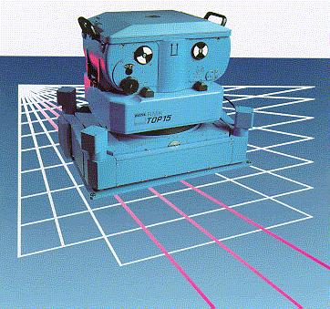
4 Aerial camera with viewfinder and electronic control

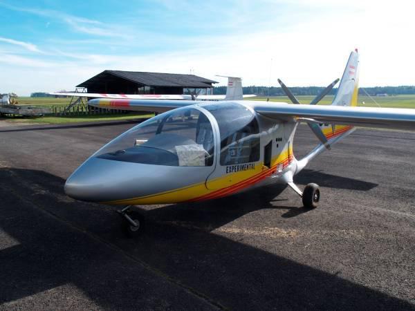
5 Aerial Camera in action
6 Single lens Frame Cameras Standard is 9 (23 cm) frame size and 6 (15.24 cm) focal length( f). They can be classified, as mentioned before, according to the field of view to: Normal angle ( up to 75 ) Wide angle (up to 75 ) Super-wide angle (greater than to 75 )
7 Components of a single frame film camera. Three main parts: 1. Magazine 2. Body 3. Lens cone assembly Components and notes to be discussed din lecture

8
9

10 Components of a single frame film camera. Fiducial Marks A vertical Photograph

11 Components of a single frame film camera. Example of a corner Fiducial Mark under Magnification
12

13 Airborne and Spaceborne Imagery
14 Geometry of aerial cameras Principal Point (P.P) L:
15 Geometry of aerial cameras Identify the following: - L: perspective center. - Fiducial Center F.C. - Principal Point (P.P) or O: the point where the perpendicular from the perspective center intersects the photograph. Usually deviates from the F.C by a very small distance. - Principal axis: the line perpendicular from the principal center on the plane of the photograph (negative). - f the focal length, equals the Principal Distance.
16 Types of Photographs (by tilt) Aerial Photos are: 1- Vertical or tilted Vertical photos are taken with the optical axis (Principal Line) vertical or tilted by no more than 2 Tilted: if the optical axis is tilted by no more than 3

17 Types of Photographs (by tilt) 2- Oblique Photos If the optical axis is intentionally strongly tilted to increase coverage, they are: Low oblique: if the tilt is not enough to show the horizon, usually 3 to 30 Low Oblique Photo

18 Types of Photographs (by tilt) 2- Oblique Photos Low oblique High oblique: if the horizon is shown on the photograph High oblique Low oblique

19 High Oblique Vertical Photograph y x

20 Example of vertical, high, and low oblique photos

21 Types of Photographs (by tilt) 3- Convergent Photographs Low oblique photos in which camera axis converge toward one another Low Oblique Photo
22 Comparison between vertical and Coverage Geometry Low cloud? oblique photos View: issues with tall features and views of sides of features. Others

23 Photo Coordinates (film) We use positives for ease of geometry and familiarity of feature shapes, negatives may be used in certain applications Lines connecting middle fiducials ON THE POSITIVE define a photo coordinate system, in which x is in the direction of flight, A RIGHT-HAND coordinate system Measurements can be as accurate as 1 micron = 1/1000 mm y x

24 Photo Coordinates (digital) Pixels in a digital image represent coordinates of rows and columns.
25
26
27

28 Geometry of a vertical photographs The line LoO, the optical axis is assumed truly vertical Direction of flight
29

30 Geometry of a digital frame camera Similar geometry is assumed in case of a digital camera Uses a two dimensional array of CCD elements mounted at the focal plane of the camera. The image is a grid of picture elements (pixels)
31 Similar geometry is assumed in case of a digital camera Uses a two dimensional array of CCD elements mounted at the focal plane of the camera. The image is a grid of picture elements (pixels) The size of pixels in one image represent the resolution of the image, the smaller the pixel, the higher (better) the resolution. A mega (million) pixel image includes one million pixel Number of pixels can be as low as 500X500 = 250,000 pixels, or megas of pixels for commercial cameras, or gegapixels in classified cameras. What is the size of image of a camera that includes a CCD frame sensor, that is 1024 X1024 elements, if the size of a pixels is 5? How many megapixels are there? Answer: image size = 1024 X = 5.12 mm, No of pixels = 1024X1024= 1 mega pixel

32 Digital image resolution

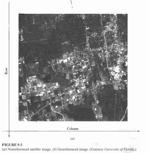
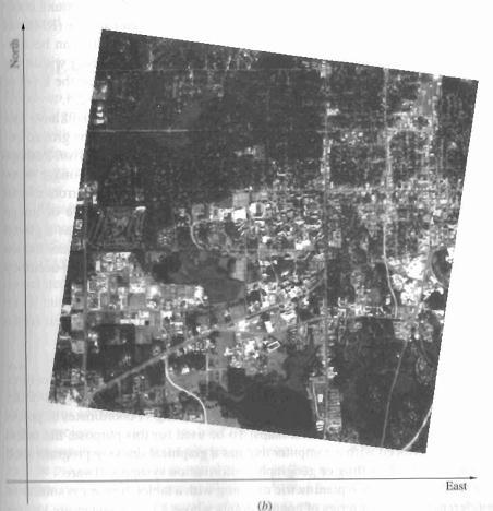
33 image taken from a firstgeneration Landsat satellite over Milwaukee, Wisconsin.

34 1-m resolution image obtained from the IKONOS satellite showing San Francisco.

35 Concept of image pyramids
36
37
38 linear array sensors A linear CCD scans the ground at a given time. The vehicle advances a distance equals to one array and capture the next line. Will the entire image be scanned at the same time?
39 Flying spot scanner: The geometry is such that the after a row is finished being scanned, the vehicle advanced to the beginning of the next row. Which digital system is suitable for what purpose?? Why??
40 Image coordinate corrections Our goal is to measure photo coordinates and relate them to ground coordinates by equations to obtain ground coordinates. Once you have ground coordinates, you can draw a map, establish cross section, etc. Measured photo coordinates need to be corrected prior to substation in equations, for the following: Film shrinkage Principal point location Lens distortions Atmospheric refraction Earth curvature Which of the corrections inapplicable for digital images??
41 Effect of Earth Curvature
42 Atmospheric Refraction
43 Vertical Photographs
44 Scale of a Vertical Photograph Scale of a photograph is the ratio of a distance on a photo to the same distance on the ground. Photographs are not maps, why? Scale of a map and scale of a photograph. Orthphotos (orthophoto maps), what are they? Scale (s) at any point: S = f H - h Average scale of a photograph: S avg = f H - h avg If the f, H, and h are not available, but a map is available then: Photo Scale = photo distance X map scale map distance
45

46 Scale of a vertical photograph.
47 Ground Coordinates from a Single Vertical Photograph With image coordinate system defined, we may define an arbitrary ground coordinate system parallel to (x,y) origin at nadir. That ground system could be used to compute distances and azimuths. Coordinates can also be transformed to any system In that ground system: X a = x a * (photograph scale at a) Y a = y a * (photograph scale at a)
48
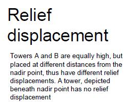
49 Relief Displacement on a Vertical Photograph The shift of an image from its theoretical datum location caused by the object s relief. Two points on a vertical line will appear as one line on a map, but two points, usually, on a photograph. The displacement is from the photgraphic nadir point. In a vertical photo, the displacement is from the principal point, which is the nadir in this case. Photographic Nadir point is where the vertical from the Exposure Station intersects the photograph.
50

51 Relief displacement from Nadir (enlarged)

52 Relief displacement from Nadir (Center )
 then; (r b * H) (r a *H) = r b h d = r b - r a = r b *h b /H Now, what about b and c? What would d c wrt b equals?")
53 r a /R = f/h Or: r a *H = R * f ----(1) r b /R = f/(h-h) Or: r b * (H-h) =R * f ---(2) Then from (1) and (2); r a *H = r b * (H-h) then; (r b * H) (r a *H) = r b h d = r b - r a = r b *h b /H Now, what about b and c? What would d c wrt b equals?
54 Relief displacement (d) of a point wrt a point on the datum : d = r h H where: r: is the radial distance on the photo to the high point h : elevation of the high point, and H is flying height above datum Assuming that the datum is at the bottom of vertical object, H is the flying height above ground, the value h will compute the object height.
55 Or, in general: Assume that point C is vertically above B, they are shown on the photograph as (c) and (b). Measured radial distances from the center to points c and b (r c and r b ), then d c = r c - r b and; d c = (r c * ht c ) / (flying height above ground = H h b ) Answer: d = r h/ H, then H = = 276 m H =
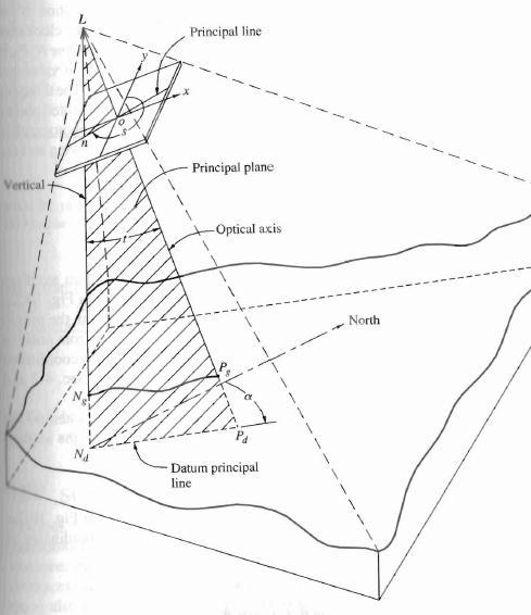
56 Tilted Photographs
57 Basic elements of a tilted photographs The optical axis is tilted from the vertical Identify the following: - t = angle of tilt between the plumb line and the optical axis L0
58
59
60
61 i m i
62 What and why an auxiliary coordinate system? A step to relate photo coordinates to ground, because the photograph is tilted. Thus, photo and ground coordinates are not parallel any more. You need a system in between as a step to transfer photo coordinates to ground, specially that tilt is variable.
63 Transformation from photo coordinates (x, y) to an auxiliary coordinate system (x, y ) y y x S Note that = S x
64
65 Relationship between Photo and Auxiliary coordinate system
66 Scale of a tilted Photograph The tilt of a photograph occurs around the axis of tilt in the direction of the principal line. L y n i o x
67 Scale of a tilted Photograph Scale = horizontal distance on the photo / horizontal distance on the ground = ka / KA = Lk / LK
 (y sin t), and t n t y f")
68 S = Lk / LK, but: Lk = Ln nk = (f /cost t) (y sin t), and t n t y f t
69 Also, LK = H - h A = flying height above ground Then: H h A Scale of a tilted photograph S A = f(sec t) y sin t / (H-h A )
70 Example
71
72 Ground Coordinates from a tilted photograph Coordinates of point A in a ground coordinate system X, Y where: X, Y are parallel to x and y (auxiliary system) Ground Nadir N is the origin of the ground system Note that in the auxiliary coordinate system, lines parallel to x are horizontal, thus x on the photo is horizontal and directly related to ground X by the scale, or X A =x /S A
73 t y But in the auxiliary system, y is in the direction of maximum tilt and not horizontal, the scale is ratio between horizontal projections. Ka: Horizontal projection of y = y cos t Then, Y = y cos t / S n
74 Example
75
Volume 1 - Module 6 Geometry of Aerial Photography. I. Classification of Photographs. Vertical
 RSCC Volume 1 Introduction to Photo Interpretation and Photogrammetry Table of Contents Module 1 Module 2 Module 3.1 Module 3.2 Module 4 Module 5 Module 6 Module 7 Module 8 Labs Volume 1 - Module 6 Geometry
Following are the geometrical elements of the aerial photographs:
 Geometrical elements/characteristics of aerial photograph: An aerial photograph is a central or perspective projection, where the bundles of perspective rays meet at a point of origin called perspective
Sample Copy. Not For Distribution.
 Photogrammetry, GIS & Remote Sensing Quick Reference Book i EDUCREATION PUBLISHING Shubham Vihar, Mangla, Bilaspur, Chhattisgarh - 495001 Website: www.educreation.in Copyright, 2017, S.S. Manugula, V.
not to be republished NCERT Introduction To Aerial Photographs Chapter 6
 Chapter 6 Introduction To Aerial Photographs Figure 6.1 Terrestrial photograph of Mussorrie town of similar features, then we have to place ourselves somewhere in the air. When we do so and look down,
Aerial photography: Principles. Frame capture sensors: Analog film and digital cameras
 Aerial photography: Principles Frame capture sensors: Analog film and digital cameras Overview Introduction Frame vs scanning sensors Cameras (film and digital) Photogrammetry Orthophotos Air photos are
11/25/2009 CHAPTER THREE INTRODUCTION INTRODUCTION (CONT D) THE AERIAL CAMERA: LENS PHOTOGRAPHIC SENSORS
 THE AERIAL CAMERA: LENS PHOTOGRAPHIC SENSORS") INTRODUCTION CHAPTER THREE IC SENSORS Photography means to write with light Today s meaning is often expanded to include radiation just outside the visible spectrum, i. e. ultraviolet and near infrared
INTRODUCTION CHAPTER THREE IC SENSORS Photography means to write with light Today s meaning is often expanded to include radiation just outside the visible spectrum, i. e. ultraviolet and near infrared
Chapters 1 & 2. Definitions and applications Conceptual basis of photogrammetric processing
 Chapters 1 & 2 Chapter 1: Photogrammetry Definitions and applications Conceptual basis of photogrammetric processing Transition from two-dimensional imagery to three-dimensional information Automation
Basics of Photogrammetry Note#6
 Basics of Photogrammetry Note#6 Photogrammetry Art and science of making accurate measurements by means of aerial photography Analog: visual and manual analysis of aerial photographs in hard-copy format
Photogrammetry. Lecture 4 September 7, 2005
 Photogrammetry Lecture 4 September 7, 2005 What is Photogrammetry Photogrammetry is the art and science of making accurate measurements by means of aerial photography: Analog photogrammetry (using films:
EXAMPLES OF TOPOGRAPHIC MAPS PRODUCED FROM SPACE AND ACHIEVED ACCURACY CARAVAN Workshop on Mapping from Space, Phnom Penh, June 2000
 EXAMPLES OF TOPOGRAPHIC MAPS PRODUCED FROM SPACE AND ACHIEVED ACCURACY CARAVAN Workshop on Mapping from Space, Phnom Penh, June 2000 Jacobsen, Karsten University of Hannover Email: karsten@ipi.uni-hannover.de
High Resolution Sensor Test Comparison with SPOT, KFA1000, KVR1000, IRS-1C and DPA in Lower Saxony
 High Resolution Sensor Test Comparison with SPOT, KFA1000, KVR1000, IRS-1C and DPA in Lower Saxony K. Jacobsen, G. Konecny, H. Wegmann Abstract The Institute for Photogrammetry and Engineering Surveys
CEE 6100 / CSS 6600 Remote Sensing Fundamentals 1 Topic 4: Photogrammetry
 CEE 6100 / CSS 6600 Remote Sensing Fundamentals 1 PHOTOGRAMMETRY DEFINITION (adapted from Manual of Photographic Interpretation, 2 nd edition, Warren Philipson, 1997) Photogrammetry and Remote Sensing:
Relief Displacement of Vertical Features
 G 210 Lab. Relief Displacement of Vertical Features An increase in the elevation of a feature causes its position on the photograph to be displaced radially outward from the principle point. Hence, when
Chapters 1-3. Chapter 1: Introduction and applications of photogrammetry Chapter 2: Electro-magnetic radiation. Chapter 3: Basic optics
 Chapters 1-3 Chapter 1: Introduction and applications of photogrammetry Chapter 2: Electro-magnetic radiation Radiation sources Classification of remote sensing systems (passive & active) Electromagnetic
Introduction to Photogeology
 Geological Mapping 1 Academic Year 2016/2017 Introduction to Photogeology Igor Vlahović igor.vlahovic@rgn.hr Today we will say a little about basic photogeological analysis of terrain: about aerial photographs,
Lab #10 Digital Orthophoto Creation (Using Leica Photogrammetry Suite)
") Lab #10 Digital Orthophoto Creation (Using Leica Photogrammetry Suite) References: Leica Photogrammetry Suite Project Manager: Users Guide, Leica Geosystems LLC. Leica Photogrammetry Suite 9.2 Introduction:
Lab #10 Digital Orthophoto Creation (Using Leica Photogrammetry Suite) References: Leica Photogrammetry Suite Project Manager: Users Guide, Leica Geosystems LLC. Leica Photogrammetry Suite 9.2 Introduction:
NRMT 2270, Photogrammetry/Remote Sensing. Lecture 4
 NRMT 2270, Photogrammetry/Remote Sensing Lecture 4 Cameras. Lenses. Photo Scale. Principles of Aerial Photography. Principle and Conjugate Principal Points. Vertical and Oblique Aerial photos. Stereo Viewing.
CHAPTER 8 AERIAL PHOTOGRAPHS
 CHAPTER 8 AERIAL PHOTOGRAPHS An aerial photograph is any photograph taken from an airborne vehicle (aircraft, drones, balloons, satellites, and so forth). The aerial photograph has many uses in military
CALIBRATION OF IMAGING SATELLITE SENSORS
 CALIBRATION OF IMAGING SATELLITE SENSORS Jacobsen, K. Institute of Photogrammetry and GeoInformation, University of Hannover jacobsen@ipi.uni-hannover.de KEY WORDS: imaging satellites, geometry, calibration
Assignment X Light. Reflection and refraction of light. (a) Angle of incidence (b) Angle of reflection (c) principle axis
 Angle of incidence (b) Angle of reflection (c) principle axis") Assignment X Light Reflection of Light: Reflection and refraction of light. 1. What is light and define the duality of light? 2. Write five characteristics of light. 3. Explain the following terms (a)
Assignment X Light Reflection of Light: Reflection and refraction of light. 1. What is light and define the duality of light? 2. Write five characteristics of light. 3. Explain the following terms (a)
LECTURE NOTES 2016 CONTENTS. Sensors and Platforms for Acquisition of Aerial and Satellite Image Data
 LECTURE NOTES 2016 Prof. John TRINDER School of Civil and Environmental Engineering Telephone: (02) 9 385 5020 Fax: (02) 9 313 7493 j.trinder@unsw.edu.au CONTENTS Chapter 1 Chapter 2 Sensors and Platforms
1. Introduction 2. Tectonics of NE Iceland Krafla rifting crisis (constraints from spy image matching)
") 1. Introduction 2. Tectonics of NE Iceland 3. 1975-1984 Krafla rifting crisis (constraints from spy image matching) 4. 1975-1984 Krafla rifting crisis (constraints from aerial photos) 5. Conclusions Tuesday
1. Introduction 2. Tectonics of NE Iceland 3. 1975-1984 Krafla rifting crisis (constraints from spy image matching) 4. 1975-1984 Krafla rifting crisis (constraints from aerial photos) 5. Conclusions Tuesday
Phase One 190MP Aerial System
 White Paper Phase One 190MP Aerial System Introduction Phase One Industrial s 100MP medium format aerial camera systems have earned a worldwide reputation for its high performance. They are commonly used
Chapter 23. Mirrors and Lenses
 Chapter 23 Mirrors and Lenses Notation for Mirrors and Lenses The object distance is the distance from the object to the mirror or lens Denoted by p The image distance is the distance from the image to
NREM 345 Week 2, Material covered this week contributes to the accomplishment of the following course goal:
 NREM 345 Week 2, 2010 Reading assignment: Chapter. 4 and Sec. 5.1 to 5.2.4 Material covered this week contributes to the accomplishment of the following course goal: Goal 1: Develop the understanding and
Waves & Oscillations
 Physics 42200 Waves & Oscillations Lecture 33 Geometric Optics Spring 2013 Semester Matthew Jones Aberrations We have continued to make approximations: Paraxial rays Spherical lenses Index of refraction
Chapter 23. Mirrors and Lenses
 Chapter 23 Mirrors and Lenses Mirrors and Lenses The development of mirrors and lenses aided the progress of science. It led to the microscopes and telescopes. Allowed the study of objects from microbes
PHOTOGRAMMETRY STEREOSCOPY FLIGHT PLANNING PHOTOGRAMMETRIC DEFINITIONS GROUND CONTROL INTRODUCTION
 PHOTOGRAMMETRY STEREOSCOPY FLIGHT PLANNING PHOTOGRAMMETRIC DEFINITIONS GROUND CONTROL INTRODUCTION Before aerial photography and photogrammetry became a reliable mapping tool, planimetric and topographic
CALIBRATION OF OPTICAL SATELLITE SENSORS
 CALIBRATION OF OPTICAL SATELLITE SENSORS KARSTEN JACOBSEN University of Hannover Institute of Photogrammetry and Geoinformation Nienburger Str. 1, D-30167 Hannover, Germany jacobsen@ipi.uni-hannover.de
PROPERTY OF THE LARGE FORMAT DIGITAL AERIAL CAMERA DMC II
 PROPERTY OF THE LARGE FORMAT DIGITAL AERIAL CAMERA II K. Jacobsen a, K. Neumann b a Institute of Photogrammetry and GeoInformation, Leibniz University Hannover, Germany jacobsen@ipi.uni-hannover.de b Z/I
Chapter 18 Optical Elements
 Chapter 18 Optical Elements GOALS When you have mastered the content of this chapter, you will be able to achieve the following goals: Definitions Define each of the following terms and use it in an operational
LENSES. INEL 6088 Computer Vision
 LENSES INEL 6088 Computer Vision Digital camera A digital camera replaces film with a sensor array Each cell in the array is a Charge Coupled Device light-sensitive diode that converts photons to electrons
Lecture 4: Geometrical Optics 2. Optical Systems. Images and Pupils. Rays. Wavefronts. Aberrations. Outline
 Lecture 4: Geometrical Optics 2 Outline 1 Optical Systems 2 Images and Pupils 3 Rays 4 Wavefronts 5 Aberrations Christoph U. Keller, Leiden University, keller@strw.leidenuniv.nl Lecture 4: Geometrical
Waves & Oscillations
 Physics 42200 Waves & Oscillations Lecture 27 Geometric Optics Spring 205 Semester Matthew Jones Sign Conventions > + = Convex surface: is positive for objects on the incident-light side is positive for
Converging Lenses. Parallel rays are brought to a focus by a converging lens (one that is thicker in the center than it is at the edge).
.") Chapter 30: Lenses Types of Lenses Piece of glass or transparent material that bends parallel rays of light so they cross and form an image Two types: Converging Diverging Converging Lenses Parallel rays
Chapter 30: Lenses Types of Lenses Piece of glass or transparent material that bends parallel rays of light so they cross and form an image Two types: Converging Diverging Converging Lenses Parallel rays
Chapters 1-3. Chapter 1: Introduction and applications of photogrammetry Chapter 2: Electro-magnetic radiation. Chapter 3: Basic optics
 Chapters 1-3 Chapter 1: Introduction and applications of photogrammetry Chapter 2: Electro-magnetic radiation Radiation sources Classification of remote sensing systems (passive & active) Electromagnetic
Mapping Cameras. Chapter Three Introduction
 Chapter Three Mapping Cameras 3.1. Introduction This chapter introduces sensors used for acquiring aerial photographs. Although cameras are the oldest form of remote sensing instrument, they have changed
RADIOMETRIC AND GEOMETRIC CHARACTERISTICS OF PLEIADES IMAGES
 RADIOMETRIC AND GEOMETRIC CHARACTERISTICS OF PLEIADES IMAGES K. Jacobsen a, H. Topan b, A.Cam b, M. Özendi b, M. Oruc b a Leibniz University Hannover, Institute of Photogrammetry and Geoinformation, Germany;
2019 NYSAPLS Conf> Fundamentals of Photogrammetry for Land Surveyors
 2019 NYSAPLS Conf> Fundamentals of Photogrammetry for Land Surveyors George Southard GSKS Associates LLC Introduction George Southard: Master s Degree in Photogrammetry and Cartography 40 years working
LENSES. A lens is any glass, plastic or transparent refractive medium with two opposite faces, and at least one of the faces must be curved.
 1 LENSES A lens is any glass, plastic or transparent refractive medium with two opposite faces, and at least one of the faces must be curved. Types of Lenses There are two types of basic lenses: Converging/
Atmospheric interactions; Aerial Photography; Imaging systems; Intro to Spectroscopy Week #3: September 12, 2018
 GEOL 1460/2461 Ramsey Introduction/Advanced Remote Sensing Fall, 2018 Atmospheric interactions; Aerial Photography; Imaging systems; Intro to Spectroscopy Week #3: September 12, 2018 I. Quick Review from
Chapter 23. Mirrors and Lenses
 Chapter 23 Mirrors and Lenses Notation for Mirrors and Lenses The object distance is the distance from the object to the mirror or lens Denoted by p The image distance is the distance from the image to
Lenses. A lens is any glass, plastic or transparent refractive medium with two opposite faces, and at least one of the faces must be curved.
 PHYSICS NOTES ON A lens is any glass, plastic or transparent refractive medium with two opposite faces, and at least one of the faces must be curved. Types of There are two types of basic lenses. (1.)
AERIAL PHOTOGRAPHS CHAPTER 8
 CHAPTER 8 AERIAL PHOTOGRAPHS An aerial photograph is any photograph taken from an airborne vehicle (aircraft, drones, balloons) satellites, and so forth). The aerial photograph has many uses in military
Notation for Mirrors and Lenses. Chapter 23. Types of Images for Mirrors and Lenses. More About Images
 Notation for Mirrors and Lenses Chapter 23 Mirrors and Lenses Sections: 4, 6 Problems:, 8, 2, 25, 27, 32 The object distance is the distance from the object to the mirror or lens Denoted by p The image
Optical Components for Laser Applications. Günter Toesko - Laserseminar BLZ im Dezember
 Günter Toesko - Laserseminar BLZ im Dezember 2009 1 Aberrations An optical aberration is a distortion in the image formed by an optical system compared to the original. It can arise for a number of reasons
Spherical Mirrors. Concave Mirror, Notation. Spherical Aberration. Image Formed by a Concave Mirror. Image Formed by a Concave Mirror 4/11/2014
 Notation for Mirrors and Lenses Chapter 23 Mirrors and Lenses The object distance is the distance from the object to the mirror or lens Denoted by p The image distance is the distance from the image to
Class-X Assignment (Chapter-10) Light-Reflection & Refraction
 Light-Reflection & Refraction") Class-X Assignment (Chapter-10) Light-Reflection & Refraction Q 1. How does light enable us to see an object? Q 2. What is a concave mirror? Q 3. What is the relationship between focal length and radius
Class-X Assignment (Chapter-10) Light-Reflection & Refraction Q 1. How does light enable us to see an object? Q 2. What is a concave mirror? Q 3. What is the relationship between focal length and radius
Cameras. CSE 455, Winter 2010 January 25, 2010
 Cameras CSE 455, Winter 2010 January 25, 2010 Announcements New Lecturer! Neel Joshi, Ph.D. Post-Doctoral Researcher Microsoft Research neel@cs Project 1b (seam carving) was due on Friday the 22 nd Project
Lenses. Images. Difference between Real and Virtual Images
 Linear Magnification (m) This is the factor by which the size of the object has been magnified by the lens in a direction which is perpendicular to the axis of the lens. Linear magnification can be calculated
Remote Sensing. Ch. 3 Microwaves (Part 1 of 2)
") Remote Sensing Ch. 3 Microwaves (Part 1 of 2) 3.1 Introduction 3.2 Radar Basics 3.3 Viewing Geometry and Spatial Resolution 3.4 Radar Image Distortions 3.1 Introduction Microwave (1cm to 1m in wavelength)
Remote Sensing Ch. 3 Microwaves (Part 1 of 2) 3.1 Introduction 3.2 Radar Basics 3.3 Viewing Geometry and Spatial Resolution 3.4 Radar Image Distortions 3.1 Introduction Microwave (1cm to 1m in wavelength)
10.2 Images Formed by Lenses SUMMARY. Refraction in Lenses. Section 10.1 Questions
 10.2 SUMMARY Refraction in Lenses Converging lenses bring parallel rays together after they are refracted. Diverging lenses cause parallel rays to move apart after they are refracted. Rays are refracted
E X P E R I M E N T 12
 E X P E R I M E N T 12 Mirrors and Lenses Produced by the Physics Staff at Collin College Copyright Collin College Physics Department. All Rights Reserved. University Physics II, Exp 12: Mirrors and Lenses
Airborne or Spaceborne Images for Topographic Mapping?
 Advances in Geosciences Konstantinos Perakis, Editor EARSeL, 2012 Airborne or Spaceborne Images for Topographic Mapping? Karsten Jacobsen Leibniz University Hannover, Institute of Photogrammetry and Geoinformation,
OPTICAL SYSTEMS OBJECTIVES
 101 L7 OPTICAL SYSTEMS OBJECTIVES Aims Your aim here should be to acquire a working knowledge of the basic components of optical systems and understand their purpose, function and limitations in terms
Remote Sensing. Measuring an object from a distance. For GIS, that means using photographic or satellite images to gather spatial data
 Remote Sensing Measuring an object from a distance For GIS, that means using photographic or satellite images to gather spatial data Remote Sensing measures electromagnetic energy reflected or emitted
Jens Kremer ISPRS Hannover Workshop 2017,
 Jens Kremer ISPRS Hannover Workshop 2017, 8.06.2017 Modular aerial camera-systems The IGI UrbanMapper 2-in1 concept System Layout The DigiCAM-100 module The IGI UrbanMapper Sensor geometry & stitching
Complete the diagram to show what happens to the rays. ... (1) What word can be used to describe this type of lens? ... (1)
 What word can be used to describe this type of lens? ... (1)") Q1. (a) The diagram shows two parallel rays of light, a lens and its axis. Complete the diagram to show what happens to the rays. (2) Name the point where the rays come together. (iii) What word can be
Q1. (a) The diagram shows two parallel rays of light, a lens and its axis. Complete the diagram to show what happens to the rays. (2) Name the point where the rays come together. (iii) What word can be
VisionMap Sensors and Processing Roadmap
 Vilan, Gozes 51 VisionMap Sensors and Processing Roadmap YARON VILAN, ADI GOZES, Tel-Aviv ABSTRACT The A3 is a family of digital aerial mapping cameras and photogrammetric processing systems, which is
RPAS Photogrammetric Mapping Workflow and Accuracy
 RPAS Photogrammetric Mapping Workflow and Accuracy Dr Yincai Zhou & Dr Craig Roberts Surveying and Geospatial Engineering School of Civil and Environmental Engineering, UNSW Background RPAS category and
Colorado School of Mines. Computer Vision. Professor William Hoff Dept of Electrical Engineering &Computer Science.
 Professor William Hoff Dept of Electrical Engineering &Computer Science http://inside.mines.edu/~whoff/ 1 Sensors and Image Formation Imaging sensors and models of image formation Coordinate systems Digital
Computer Vision. The Pinhole Camera Model
 Computer Vision The Pinhole Camera Model Filippo Bergamasco (filippo.bergamasco@unive.it) http://www.dais.unive.it/~bergamasco DAIS, Ca Foscari University of Venice Academic year 2017/2018 Imaging device
Dr F. Cuzzolin 1. September 29, 2015
 P00407 Principles of Computer Vision 1 1 Department of Computing and Communication Technologies Oxford Brookes University, UK September 29, 2015 September 29, 2015 1 / 73 Outline of the Lecture 1 2 Basics
HIGH RESOLUTION COLOR IMAGERY FOR ORTHOMAPS AND REMOTE SENSING. Author: Peter Fricker Director Product Management Image Sensors
 HIGH RESOLUTION COLOR IMAGERY FOR ORTHOMAPS AND REMOTE SENSING Author: Peter Fricker Director Product Management Image Sensors Co-Author: Tauno Saks Product Manager Airborne Data Acquisition Leica Geosystems
Camera Calibration Certificate No: DMC III 27542
 Calibration DMC III Camera Calibration Certificate No: DMC III 27542 For Peregrine Aerial Surveys, Inc. #201 1255 Townline Road Abbotsford, B.C. V2T 6E1 Canada Calib_DMCIII_27542.docx Document Version
TELLS THE NUMBER OF PIXELS THE TRUTH? EFFECTIVE RESOLUTION OF LARGE SIZE DIGITAL FRAME CAMERAS
 TELLS THE NUMBER OF PIXELS THE TRUTH? EFFECTIVE RESOLUTION OF LARGE SIZE DIGITAL FRAME CAMERAS Karsten Jacobsen Leibniz University Hannover Nienburger Str. 1 D-30167 Hannover, Germany jacobsen@ipi.uni-hannover.de
IMAGE FORMATION. Light source properties. Sensor characteristics Surface. Surface reflectance properties. Optics
 IMAGE FORMATION Light source properties Sensor characteristics Surface Exposure shape Optics Surface reflectance properties ANALOG IMAGES An image can be understood as a 2D light intensity function f(x,y)
University Of Lübeck ISNM Presented by: Omar A. Hanoun
 University Of Lübeck ISNM 12.11.2003 Presented by: Omar A. Hanoun What Is CCD? Image Sensor: solid-state device used in digital cameras to capture and store an image. Photosites: photosensitive diodes
The Z/I Imaging Digital Aerial Camera System
 Hinz 109 The Z/I Imaging Digital Aerial Camera System ALEXANDER HINZ, Oberkochen ABSTRACT With the availability of a digital camera, it is possible to completely close the digital chain from image recording
Unit 1: Image Formation
 Unit 1: Image Formation 1. Geometry 2. Optics 3. Photometry 4. Sensor Readings Szeliski 2.1-2.3 & 6.3.5 1 Physical parameters of image formation Geometric Type of projection Camera pose Optical Sensor
Lab 11: Lenses and Ray Tracing
 Name: Lab 11: Lenses and Ray Tracing Group Members: Date: TA s Name: Materials: Ray box, two different converging lenses, one diverging lens, screen, lighted object, three stands, meter stick, two letter
REFLECTION THROUGH LENS
 REFLECTION THROUGH LENS A lens is a piece of transparent optical material with one or two curved surfaces to refract light rays. It may converge or diverge light rays to form an image. Lenses are mostly
CSI: Rombalds Moor Photogrammetry Photography
 Photogrammetry Photography Photogrammetry Training 26 th March 10:00 Welcome Presentation image capture Practice 12:30 13:15 Lunch More practice 16:00 (ish) Finish or earlier What is photogrammetry 'photo'
Camera Calibration Certificate No: DMC II
 Calibration DMC II 230 015 Camera Calibration Certificate No: DMC II 230 015 For Air Photographics, Inc. 2115 Kelly Island Road MARTINSBURG WV 25405 USA Calib_DMCII230-015_2014.docx Document Version 3.0
Lecture 2: Geometrical Optics. Geometrical Approximation. Lenses. Mirrors. Optical Systems. Images and Pupils. Aberrations.
 Lecture 2: Geometrical Optics Outline 1 Geometrical Approximation 2 Lenses 3 Mirrors 4 Optical Systems 5 Images and Pupils 6 Aberrations Christoph U. Keller, Leiden Observatory, keller@strw.leidenuniv.nl
Lens Principal and Nodal Points
 Lens Principal and Nodal Points Douglas A. Kerr, P.E. Issue 3 January 21, 2004 ABSTRACT In discussions of photographic lenses, we often hear of the importance of the principal points and nodal points of
LIGHT REFLECTION AND REFRACTION
 LIGHT REFLECTION AND REFRACTION 1. List four properties of the image formed by a plane mirror. Properties of image formed by a plane mirror: 1. It is always virtual and erect. 2. Its size is equal to that
Gaussian Ray Tracing Technique
 Gaussian Ray Tracing Technique Positive Lenses. A positive lens has two focal points one on each side of the lens; both are at the same focal distance f from the lens. Parallel rays of light coming from
Chapter 36. Image Formation
 Chapter 36 Image Formation Image of Formation Images can result when light rays encounter flat or curved surfaces between two media. Images can be formed either by reflection or refraction due to these
Consumer digital CCD cameras
 CAMERAS Consumer digital CCD cameras Leica RC-30 Aerial Cameras Zeiss RMK Zeiss RMK in aircraft Vexcel UltraCam Digital (note multiple apertures Lenses for Leica RC-30. Many elements needed to minimize
What is Photogrammetry
 Photogrammetry What is Photogrammetry Photogrammetry is the art and science of making accurate measurements by means of aerial photography: Analog photogrammetry (using films: hard-copy photos) Digital
Lecture 3: Geometrical Optics 1. Spherical Waves. From Waves to Rays. Lenses. Chromatic Aberrations. Mirrors. Outline
 Lecture 3: Geometrical Optics 1 Outline 1 Spherical Waves 2 From Waves to Rays 3 Lenses 4 Chromatic Aberrations 5 Mirrors Christoph U. Keller, Leiden Observatory, keller@strw.leidenuniv.nl Lecture 3: Geometrical
EVALUATION OF PLEIADES-1A TRIPLET ON TRENTO TESTFIELD
 EVALUATION OF PLEIADES-1A TRIPLET ON TRENTO TESTFIELD D. Poli a, F. Remondino b, E. Angiuli c, G. Agugiaro b a Terra Messflug GmbH, Austria b 3D Optical Metrology Unit, Fondazione Bruno Kessler, Trento,
Principles of Photogrammetry
 Winter 2014 1 Instructor: Contact Information. Office: Room # ENE 229C. Tel: (403) 220-7105. E-mail: ahabib@ucalgary.ca Lectures (SB 148): Monday, Wednesday& Friday (10:00 a.m. 10:50 a.m.). Office Hours:
Chapter 36. Image Formation
 Chapter 36 Image Formation Notation for Mirrors and Lenses The object distance is the distance from the object to the mirror or lens Denoted by p The image distance is the distance from the image to the
Opto Engineering S.r.l.
 TUTORIAL #1 Telecentric Lenses: basic information and working principles On line dimensional control is one of the most challenging and difficult applications of vision systems. On the other hand, besides
Figure 1 - The Main Screen of the e-foto Photogrammetric Project Creation and Management
 Introduction The Rio de Janeiro State University - UERJ After executing the integrated version of the e-foto, you will see the opening screen of the software, as shown in Figure 1 below. The main menu
Algebra Based Physics. Reflection. Slide 1 / 66 Slide 2 / 66. Slide 3 / 66. Slide 4 / 66. Slide 5 / 66. Slide 6 / 66.
 Slide 1 / 66 Slide 2 / 66 Algebra Based Physics Geometric Optics 2015-12-01 www.njctl.org Slide 3 / 66 Slide 4 / 66 Table of ontents lick on the topic to go to that section Reflection Refraction and Snell's
Chapter 23. Geometrical Optics: Mirrors and Lenses and other Instruments
 Chapter 23 Geometrical Optics: Mirrors and Lenses and other Instruments HITT 1 You stand two feet away from a plane mirror. How far is it from you to your image? a. 2.0 ft b. 3.0 ft c. 4.0 ft d. 5.0 ft
Image and Multidimensional Signal Processing
 Image and Multidimensional Signal Processing Professor William Hoff Dept of Electrical Engineering &Computer Science http://inside.mines.edu/~whoff/ Digital Image Fundamentals 2 Digital Image Fundamentals
Lesson 12. Stereoscopy and Photo Preparation. Steven J. Steinberg
 Lesson 12 Stereoscopy and Photo Preparation Steven J. Steinberg Description: The lessons in this section focus on stereoscopy and photo preparation. We begin with a discussion of the principles of stereoscopy.
CHARACTERISTICS OF VERY HIGH RESOLUTION OPTICAL SATELLITES FOR TOPOGRAPHIC MAPPING
 CHARACTERISTICS OF VERY HIGH RESOLUTION OPTICAL SATELLITES FOR TOPOGRAPHIC MAPPING K. Jacobsen Leibniz University Hannover, Institute of Photogrammetry and Geoinformation jacobsen@ipi.uni-hannover.de Commission
Calibration Certificate
 Calibration Certificate Digital Mapping Camera (DMC) DMC Serial Number: DMC01-0053 CBU Serial Number: 0100053 For MPPG AERO Sp. z. o. o., ul. Kaczkowskiego 6 33-100 Tarnow Poland System Overview Flight
ACTIVE SENSORS RADAR
 ACTIVE SENSORS RADAR RADAR LiDAR: Light Detection And Ranging RADAR: RAdio Detection And Ranging SONAR: SOund Navigation And Ranging Used to image the ocean floor (produce bathymetic maps) and detect objects
Phys 531 Lecture 9 30 September 2004 Ray Optics II. + 1 s i. = 1 f
 Phys 531 Lecture 9 30 September 2004 Ray Optics II Last time, developed idea of ray optics approximation to wave theory Introduced paraxial approximation: rays with θ 1 Will continue to use Started disussing
Experimental aerial photogrammetry with professional non metric camera Canon EOS 5D
 Experimental aerial photogrammetry with professional non metric camera Canon EOS 5D Ante Sladojević, Goran Mrvoš Galileo Geo Sustavi, Croatia 1. Introduction With this project we wanted to test professional
Lecture 2: Geometrical Optics. Geometrical Approximation. Lenses. Mirrors. Optical Systems. Images and Pupils. Aberrations.
 Lecture 2: Geometrical Optics Outline 1 Geometrical Approximation 2 Lenses 3 Mirrors 4 Optical Systems 5 Images and Pupils 6 Aberrations Christoph U. Keller, Leiden Observatory, keller@strw.leidenuniv.nl
Lesson 4: Photogrammetry
 This work by the National Information Security and Geospatial Technologies Consortium (NISGTC), and except where otherwise Development was funded by the Department of Labor (DOL) Trade Adjustment Assistance
Philpot & Philipson: Remote Sensing Fundamentals Scanners 8.1 W.D. Philpot, Cornell University, Fall 2015
 Philpot & Philipson: Remote Sensing Fundamentals Scanners 8.1 8. SCANNERS 8.1 General Scanners are scanning radiometers which, when operated from an airborne or spaceborne platform, image the terrain in
Phase One ixu-rs1000 Accuracy Assessment Report Yu. Raizman, PhaseOne.Industrial, Israel
 17 th International Scientific and Technical Conference FROM IMAGERY TO DIGITAL REALITY: ERS & Photogrammetry Phase One ixu-rs1000 Accuracy Assessment Report Yu. Raizman, PhaseOne.Industrial, Israel 1.