Amplifiers and Feedback Theory. Alessandro Spinelli Phone: ( ) 4001 home.deib.polimi.
|
|
|
- Vivien Ryan
- 5 years ago
- Views:
Transcription
1 Amplifiers and Feedback Theory Phone: ( ) 4001 home.deib.polimi.it/spinelli
2 Slides are supplementary material and are NOT a replacement for textbooks and/or lecture notes
3 Outline Review: equivalent circuits Amplifiers Negative feedback Operational amplifiers


4 The origin Hermann von Helmholtz ( ) Lèon Charles Thévenin ( ) Hans Ferdinand Mayer ( ) Edward Lawry Norton ( ) From [1]
5 Equivalent circuits Every linear network «seen» between any pair of terminals behaves as if composed by a source and an impedance only Thévenin equivalent circuit: voltage source with impedance in series Norton equivalent circuit: current source with impedance in parallel
6 Equivalent circuits Sources and linear elements II VV Same ZZ eeee ZZ eeee II VV ZZ eeee II VV VV eeee II eeee Equivalence is only from the viewpoint of the external load. Power dissipation, for example, is not equal
7 Element calculations VV eeee is the open-circuit voltage at the terminals II eeee is the short-circuit current through the terminals ZZ eeee = VV eeee /II eeee, or equivalently ZZ eeee is the impedance between the terminals when voltage sources are replaced by short-circuits current sources are replaced by open circuits
8 Outline Review: equivalent circuits Amplifiers Negative feedback Operational amplifiers
9 Amplifiers We consider a «black box» approach with equivalent circuits Four kinds can be identified: In Out Type V V Voltage ampl. I I Current ampl. V I Transconductance ampl. I V Transresistance ampl.
10 Voltage/current amplifiers RR II ii II oo oo RR oo VV ii RR ii VV oo RR ii AA VV VV ii AA II II ii Voltage-controlled voltage source (VCVS) Current-controlled current source (CCCS) One-directional amplifiers (no reverse transfer from output to input) Resistors will be considered for simplicity, though complex impedances can be assumed
11 Source and load resistors (VA) RR ss RR ii VV ss AA VV VV ii RR oo RR LL VV oo VV ii VV ii = VV SS RR ii RR ii + RR SS VV oo = AA VV VV ii RR LL RR oo + RR LL
12 Voltage gain VV oo VV SS = AA VV RR LL RR oo + RR LL RR ii RR ii + RR SS Total gain is less than AA VV Gain is dependent on RR SS and RR LL To avoid these drawbacks, a voltage amplifier should have RR ii = (very high input impedance) RR oo = 0 (very low output impedance)
13 Source and load resistors (CA) RR ss II ii RR oo II oo II ss RR ii RRLL AA II II ii II ii = II SS RR SS RR ii + RR SS II oo = AA II II ii RR oo RR oo + RR LL
14 Current gain II oo II SS = AA II RR oo RR oo + RR LL RR SS RR ii + RR SS Total gain is less than AA II Gain is dependent on RR SS and RR LL To avoid these drawbacks a current amplifier should have RR ii = 0 (very low input impedance) RR oo = (very high output impedance)
15 Summary Type RR ii RR oo Voltage amplifier 0 Current amplifier 0 Transconductance ampl. Transresistance ampl. 0 0
16 Outline Review: equivalent circuits Amplifiers Negative feedback Operational amplifiers
17 American telephone lines First transcontinental telephone line built in 1914 (announced 1915), upgraded in 1921 to three channels and using twelve amplifiers Second line built in 1923 with four channels and twenty amplifiers A further increase in the number of channels was very, very challenging
18 The amplifier problem Signal is attenuated as it propagates along the wires and must be regenerated Gain of vacuum-tube amplifiers changes with plate voltage, temperature, aging, Non-linearity creates intermodulation distorsion in multi-channel systems
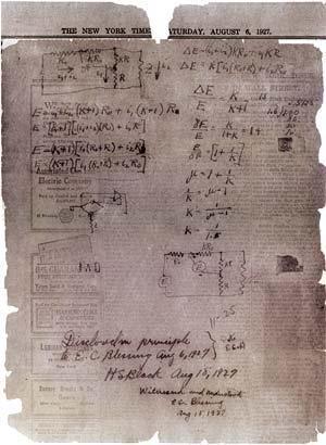
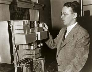
19 Negative-feedback concept Harold S. Black ( ) From [2]
20 The theory SS iiii + - εε GG OOOO SS oooooo FFSS oooooo FF εε = SS iiii FFSS oooooo SS oooooo = GG OOOO εε SS oooooo SS iiii = GG = GG OOOO 1 + GG OOOO FF
21 Closed-loop gain GG OOOO FF 1 GG = GG OOOO 1 + GG OOOO FF ~GG OOOO Open-loop gain, no feedback GG OOOO FF 1 GG = GG OOOO 1 + GG OOOO FF ~ 1 FF = GG iiii Ideal gain, independent of GG OOOO
22 Loop gain calculation SS tttttttt - GG OOOO FFSS tttttttt GG OOOO FF GG OOOO SS tttttttt GG llllllll = GG OOOO FF measures the strength of the feedback A good feedback system has GG llllllll < 0 and GG llllllll 1
23 GG = Loop gain interpretation GG OOOO 1 + GG OOOO FF = 1/FF 1 + 1/GG OOOO FF = GG iiii 1 1/GG llllllll 1/ GG llllllll is the error between GG and GG iiii : Ex: GG OOOO = 10 5, FF = 10 2 GG llllllll = 1000, GG iiii = 100, GG = 99.9 εε = = 1/ GG llllllll In fact, the error signal εε = SS iiii FFSS oooooo is εε = 1 FFGG = GG iiii GG 1 = ~ 1 SS iiii GG iiii 1 GG llllllll GG llllllll
24 Sensitivity to GG OOOO dddd ddgg OOOO = GG OOOO FF 2 = GG 1 GG OOOO 1 GG lllloooo dddd GG = ddgg OOOO 1 <<1 GG OOOO 1 GG llllllll GG OOOO = 10 5, FF = 0.01 GG = 99.9 GG OOOO = , FF = 0.01 GG = 99.95
25 Sensitivity to FF dddd ddff = dddd GG = ddff FF 2 GG OOOO 1 + GG OOOO FF 2 = GG2 GG llllllll 1 GG llllllll -1 GG OOOO = 10 5, FF = 0.01 GG = 99.9 GG OOOO = 10 5, FF = GG = 49.98
26 Interpretation SS iiii + - εε FFSSoooooo GG OOOO FF SS oooooo Changes in GG OOOO are nulled by the feedback loop SS iiii + - εε FFSSoooooo GG OOOO FF SS oooooo Changes in FF cannot be compensated
27 Outline Review: equivalent circuits Amplifiers Negative feedback Operational amplifiers
28 Feedback amplifier design Forward (open-loop) block GG OOOO must have high gain, to ensure that GG llllllll 1. All active elements are placed here even if gain is not stable their fluctuations are reduced by 1/GG llllllll Feedback block FF must be stable, to ensure a stable closed-loop gain. Usually made with passives
29 Operational amplifiers (OAs) Integrated voltage amplifiers used as forward gain blocks in feedback circuits The ideal OA has AA = ( ) RR ii = ( Ω) RR oo = 0 ( 100 Ω) VV + VV + - εε AA + _ VV oo = AA(VV + VV )
30 Typical circuit arrangements + _ 0 + _ FF FF In ideal feedback loops εε = 0 ideal OAs keep VV + VV = 0 VV + = VV
31 References /2005Summer/timecapsule.html
Diode Circuits Recent GATE Problems
 Diode Circuits Recent GATE Problems 1. The diodes and capacitors in the circuit shown are ideal. The voltage v(t) across the diode DD 1 is CC 1 DD 2 cos(ωωωω) AC DD 1 CC 1 (a) cos(ωωωω) 1 (b) sin(ωωωω)
Homework Assignment Consider the circuit shown. Assume ideal op-amp behavior. Which statement below is true?
 Question 1 (2 points each unless noted otherwise) Homework Assignment 03 1. Consider the circuit shown. Assume ideal op-amp behavior. Which statement below is true? (a) V = VV + = 5 V (op-amp operation)
EE434 ASIC & Digital Systems
 EE434 ASIC & Digital Systems Partha Pande School of EECS Washington State University pande@eecs.wsu.edu Spring 2015 Dae Hyun Kim daehyun@eecs.wsu.edu 1 Lecture 4 More on CMOS Gates Ref: Textbook chapter
Basic Operational Amplifier Circuits
 Basic Operational Amplifier Circuits Comparators A comparator is a specialized nonlinear op-amp circuit that compares two input voltages and produces an output state that indicates which one is greater.
ELEC273 Lecture Notes Set 4, Mesh Analysis
 ELEC273 Lecture Notes Set 4, Mesh Analysis The course web site is: http://users.encs.concordia.ca/~trueman/web_page_273.htm The list of homework problems is in the course outline. For this week: Do these
An electronic unit that behaves like a voltagecontrolled
 1 An electronic unit that behaves like a voltagecontrolled voltage source. An active circuit element that amplifies, sums, subtracts, multiply, divide, differentiate or integrates a signal 2 A typical
Chapter #12: Feedback. Eng.Mohammed S. Abuwarda. Fall Semester_2017
 Chapter #12: Feedback Eng.Mohammed S. Abuwarda Fall Semester_2017 10.1. The General Feedback Structure Figure 10.1. shows the basic structure of a feedback amplifier signal-flow diagram. Open-loop amplifier
Homework Assignment 09
 Question 1 (2 points each unless noted otherwise) Homework Assignment 09 1. For SPICE, Explain very briefly the difference between the multiplier M and Meg, as in a resistor has value 2M versus a resistor
Physical Structure of CMOS Integrated Circuits
 Physical Structure of CMOS Integrated Circuits Dae Hyun Kim EECS Washington State University References John P. Uyemura, Introduction to VLSI Circuits and Systems, 2002. Chapter 3 Neil H. Weste and David
Ohm s Law. What You ll Need A computer that can run JAVA applets Calculator Paper & Pencil for calculations.
 Ohm s Law What You ll Need A computer that can run JAVA applets Calculator Paper & Pencil for calculations. Ohm s Law, shown below, is a very important in the analysis of electrical phenomena and is especially
MEMS Clocks: the next big little thing? Giorgio Mussi November 14 th, 2017
 MEMS Clocks: the next big little thing? Giorgio Mussi giorgio.mussi@polimi.it November 14 th, 2017 About me 2 Giorgio Mussi BSc+MSc in Electronics Engineering PhD with Prof. Langfelder I m in my 2 nd year
Special-Purpose Operational Amplifier Circuits
 Special-Purpose Operational Amplifier Circuits Instrumentation Amplifier An instrumentation amplifier (IA) is a differential voltagegain device that amplifies the difference between the voltages existing
or Op Amps for short
 or Op Amps for short Objective of Lecture Describe how an ideal operational amplifier (op amp) behaves. Chapter 14.1 Electrical Engineering: Principles and Applications Chapter 5.1-5.3 Fundamentals of
ECET DAQ & Control Systems
 1 Electrical Engineering Technology ECET 17700 DAQ & Control Systems Lecture # 11 Inverting Amplifier & Summer Professors Robert Herrick & J. Michael Jacob Purdue University ECET 17700 DAQ & Systems Control
CDS 101/110: Lecture 9.1 Frequency DomainLoop Shaping
 CDS /: Lecture 9. Frequency DomainLoop Shaping November 3, 6 Goals: Review Basic Loop Shaping Concepts Work through example(s) Reading: Åström and Murray, Feedback Systems -e, Section.,.-.4,.6 I.e., we
ELC 131 CIRCUIT ANALYSIS I
 ELC 131 CIRCUIT ANALYSIS I COURSE DESCRIPTION: Prerequisites: None Corequisites: MAT 121 This course introduces DC and AC electricity with emphasis on circuit analysis, measurements, and operation of test
Chapter 2. Operational Amplifiers
 Chapter 2. Operational Amplifiers Tong In Oh 1 Objective Terminal characteristics of the ideal op amp How to analyze op amp circuits How to use op amps to design amplifiers How to design more sophisticated
Analog Circuits Part 3 Operational Amplifiers
 Introductory Medical Device Prototyping Analog Circuits Part 3 Operational Amplifiers, http://saliterman.umn.edu/ Department of Biomedical Engineering, University of Minnesota Concepts to be Reviewed Operational
Analog Circuits Part 2 Semiconductors
 Introductory Medical Device Prototyping Analog Circuits Part 2 Semiconductors, http://saliterman.umn.edu/ Department of Biomedical Engineering, University of Minnesota Concepts to be Covered Semiconductors
Differential Amplifier : input. resistance. Differential amplifiers are widely used in engineering instrumentation
 Differential Amplifier : input resistance Differential amplifiers are widely used in engineering instrumentation Differential Amplifier : input resistance v 2 v 1 ir 1 ir 1 2iR 1 R in v 2 i v 1 2R 1 Differential
What s an Analog Signal?
 What s an Analog Signal? Derived from the word analogous (analogous to the original signal) Our most powerful electronic systems are digital systems, e.g. computers, however, analog signals are required
ELEC351 Lecture Notes Set 1
 ELEC351 Lecture Notes Set 1 There is a tutorial on Monday September 10! You will do the first workshop problem in the tutorial. Bring a calculator. The course web site is: www.ece.concordia.ca/~trueman/web_page_351.htm
RF Amplifier with Mirror Frequency Filter
 Radio Project ETI 041 RF Amplifier with Mirror Frequency Filter Qiran Zhou 07SOC Lunds tekniska högskola Supervisor: Göran Jönsson Abstract When using traditional RF filter, we usually need 7 to 8 orders
EE5310/EE3002: Analog Circuits. on 18th Sep. 2014
 EE5310/EE3002: Analog Circuits EC201-ANALOG CIRCUITS Tutorial 3 : PROBLEM SET 3 Due shanthi@ee.iitm.ac.in on 18th Sep. 2014 Problem 1 The MOSFET in Fig. 1 has V T = 0.7 V, and μ n C ox = 500 μa/v 2. The
ENGR 201 Homework, Fall 2018
 Chapter 1 Voltage, Current, Circuit Laws (Selected contents from Chapter 1-3 in the text book) 1. What are the following instruments? Draw lines to match them to their cables: Fig. 1-1 2. Complete the
CDS 101/110: Lecture 8.2 PID Control
 CDS 11/11: Lecture 8.2 PID Control November 16, 216 Goals: Nyquist Example Introduce and review PID control. Show how to use loop shaping using PID to achieve a performance specification Discuss the use
Lecture 2: Non-Ideal Amps and Op-Amps
 Lecture 2: Non-Ideal Amps and Op-Amps Prof. Ali M. Niknejad Department of EECS University of California, Berkeley Practical Op-Amps Linear Imperfections: Finite open-loop gain (A 0 < ) Finite input resistance
55:141 Advanced Circuit Techniques Switching Regulators
 55:141 Advanced Circuit Techniques Switching Regulators Material: ecture Notes, Handouts, and Sections of Chapter 11 of Franco A. Kruger 55:141: Advanced Circuit Techniques The University of Iowa Switching
Lab #2: Electrical Measurements II AC Circuits and Capacitors, Inductors, Oscillators and Filters
 Lab #2: Electrical Measurements II AC Circuits and Capacitors, Inductors, Oscillators and Filters Goal: In circuits with a time-varying voltage, the relationship between current and voltage is more complicated
Combination Notch and Bandpass Filter
 Combination Notch and Bandpass Filter Clever filter design for graphic equalizer can perform both notch and bandpass functions Gain or attenuation is controlled by a potentiometer for specific frequency
If You Give A Mouse A Letter He ll Want The Whole Alphabet By
 If You Give A Mouse A Letter He ll Want The Whole Alphabet By a TeachWithMe.com A If you give a mouse an A he will want a Bb. AAAA aaaa B If you give a mouse an B he will want a Cc. BBBB bbbb C If you
Useful Information Master Copy
 Useful Information Master Copy 1of10 Pantograph Ratio and Cutter Selection SINGLE LINE COPY SOLID SUNK COPY COPY MASTER HEIGHT OVERALL HEIGHT LINE WIDTH OVERALL HEIGHT The relationship between line width
Unit WorkBook 1 Level 4 ENG U22 Electronic Circuits and Devices 2018 UniCourse Ltd. All Rights Reserved. Sample
 Pearson BTEC Level 4 Higher Nationals in Engineering (RQF) Unit 22: Electronic Circuits and Devices Unit Workbook 1 in a series of 4 for this unit Learning Outcome 1 Operational Amplifiers Page 1 of 23
Electrical and Computer Engineering Department. Texas A&M University
 Electrical and Computer Engineering Department Texas A&M University ECEN 607 Advanced Analog Circuit Design Homework 1 JESSE COULON February 11, 2009 PROBLEM 1 Determination of the Order of the Amplifier
55:141 Advanced Circuit Techniques Switching Regulators
 55:141 Advanced Circuit Techniques Switching Regulators Material: ecture Notes, Handouts, and Sections of Chapter 11 of Franco A. Kruger 55:141: Advanced Circuit Techniques The University of Iowa Switching
Memory characteristics of silicon nanowire transistors generated by weak impact ionization
 Supplementary information for Memory characteristics of silicon nanowire transistors generated by weak impact ionization Doohyeok Lim, Minsuk Kim, Yoonjoong Kim, and Sangsig Kim* Department of Electrical
ECE3204 D2015 Lab 1. See suggested breadboard configuration on following page!
 ECE3204 D2015 Lab 1 The Operational Amplifier: Inverting and Non-inverting Gain Configurations Gain-Bandwidth Product Relationship Frequency Response Limitation Transfer Function Measurement DC Errors
Lecture 8: More on Operational Amplifiers (Op Amps)
") Lecture 8: More on Operational mplifiers (Op mps) Input Impedance of Op mps and Op mps Using Negative Feedback: Consider a general feedback circuit as shown. ssume that the amplifier has input impedance
Lecture 8: More on Operational mplifiers (Op mps) Input Impedance of Op mps and Op mps Using Negative Feedback: Consider a general feedback circuit as shown. ssume that the amplifier has input impedance
Applied Electronics II
 Applied Electronics II Chapter 3: Operational Amplifier Part 1- Op Amp Basics School of Electrical and Computer Engineering Addis Ababa Institute of Technology Addis Ababa University Daniel D./Getachew
Basis for Thevenin and Norton Equivalent Circuits
 Basis for Thevenin and Norton Equivalent Circuits Objective of ecture Describe the differences between ideal and real voltage and current sources Chapter 8.1 and 8.2 rinciples of Electric Circuits Demonstrate
Announcements. To stop blowing fuses in the lab, note how the breadboards are wired. EECS 42, Spring 2005 Week 3a 1
 Announcements New topics: Mesh (loop) method of circuit analysis Superposition method of circuit analysis Equivalent circuit idea (Thevenin, Norton) Maximum power transfer from a circuit to a load To stop
CHAPTER 9 FEEDBACK. NTUEE Electronics L.H. Lu 9-1
 CHAPTER 9 FEEDBACK Chapter Outline 9.1 The General Feedback Structure 9.2 Some Properties of Negative Feedback 9.3 The Four Basic Feedback Topologies 9.4 The Feedback Voltage Amplifier (Series-Shunt) 9.5
SPPL12420RH. 2 A Synchronous Rectified Step-Down Converter FEATURES DESCRIPTION RADIATION HARDNESS APPLICATIONS
 FEATURES 2 A continuous output current Input voltage capability (derating reference): 24 V Minimum input voltage: 4.5 V Minimum output voltage: 0.923 V Latch-up immune (fully isolated SOI technology) Hermetic
Two-Port Networks I. Dr. Mohamed Refky Amin
 Two-Port Networks I Amin Electronics and Electrical Communications Engineering Department (EECE) Cairo University elc.n112.eng@gmail.com http://scholar.cu.edu.eg/refky/ OUTLINE Introduction The Impedance
EE 501 Lab 11 Common mode feedback (CMFB) circuit
 circuit") EE 501 Lab 11 Common mode feedback (CMFB) circuit Objectives: Report due: November 17, 2016 1. Understand why CMFB circuits are needed and how they work to ensure robust operation. 2. Understand the advantages
EE 501 Lab 11 Common mode feedback (CMFB) circuit Objectives: Report due: November 17, 2016 1. Understand why CMFB circuits are needed and how they work to ensure robust operation. 2. Understand the advantages
SECTION 4: TRANSMISSION LINES. ESE 470 Energy Distribution Systems
 SECTION 4: TRANSMISSION LINES ESE 470 Energy Distribution Systems 2 Introduction Transmission Lines 3 Transmission and distribution of electrical power occurs over metal cables Overhead AC or DC Underground
ECE 255, MOSFET Basic Configurations
 ECE 255, MOSFET Basic Configurations 8 March 2018 In this lecture, we will go back to Section 7.3, and the basic configurations of MOSFET amplifiers will be studied similar to that of BJT. Previously,
Announcements. To stop blowing fuses in the lab, note how the breadboards are wired. EECS 42, Spring 2005 Week 3a 1
 Announcements New topics: Mesh (loop) method of circuit analysis Superposition method of circuit analysis Equivalent circuit idea (Thevenin, Norton) Maximum power transfer from a circuit to a load To stop
Analog Circuits and Systems
 Analog Circuits and Systems Prof. K Radhakrishna Rao Lecture 4 Analog Signal Processing One-Port Networks 1 Analog Signal Processing Functions ASP Amplification Filtering Oscillation Mixing, Modulation,
Lecture 16: Small Signal Amplifiers
 Lecture 16: Small Signal Amplifiers Prof. Niknejad Lecture Outline Review: Small Signal Analysis Two Port Circuits Voltage Amplifiers Current Amplifiers Transconductance Amps Transresistance Amps Example:
Bipolar Junction Transistor
 ESE 211 / Spring 2011 / Lecture 10 Bipolar Junction Transistor Let us first consider general transconductance amplifier loaded with short circuit Transconductance Obviously, power supplies are needed for
C H A P T E R 02. Operational Amplifiers
 C H A P T E R 02 Operational Amplifiers The Op-amp Figure 2.1 Circuit symbol for the op amp. Figure 2.2 The op amp shown connected to dc power supplies. The Ideal Op-amp 1. Infinite input impedance 2.
ES250: Electrical Science. HW6: The Operational Amplifier
 ES250: Electrical Science HW6: The Operational Amplifier Introduction This chapter introduces the operational amplifier or op amp We will learn how to analyze and design circuits that contain op amps,
Questions Bank of Electrical Circuits
 Questions Bank of Electrical Circuits 1. If a 100 resistor and a 60 XL are in series with a 115V applied voltage, what is the circuit impedance? 2. A 50 XC and a 60 resistance are in series across a 110V
4. Differential Amplifiers. Electronic Circuits. Prof. Dr. Qiuting Huang Integrated Systems Laboratory
 4. Differential Amplifiers Electronic Circuits Prof. Dr. Qiuting Huang Integrated Systems Laboratory Differential Signaling Basics and Motivation Transmitting information with two complementary signals
Passive Bilateral Teleoperation
 Passive Bilateral Teleoperation Project: Reconfigurable Control of Robotic Systems Over Networks Márton Lırinc Dept. Of Electrical Engineering Sapientia University Overview What is bilateral teleoperation?
EE 105 Discussion #1: Fundamentals of Circuit Analysis
 EE 105 Discussion #1: Fundamentals of Circuit Analysis 1.1 Ohm s Law V = ir i = V/R 1.2 KCL & KVL Kirchoff s Current Law (KCL) Kirchoff s Voltage Law (KVL) The algebraic sum of all currents entering a
IMPEDANCE CONVERTERS
 IMPEDANCE CONVERTERS L. GRIGORESCU Dunãrea de Jos University of Galaþi, Romania, luiza.grigorescu@ugal.ro Received September 26, 2006 From a lot of applications of current-conveyors, impedance converters
Lecture # 4 Network Analysis
 CPEN 206 Linear Circuits Lecture # 4 Network Analysis Dr. Godfrey A. Mills Email: gmills@ug.edu.gh Phone: 026-907-3163 February 22, 2016 Course TA David S. Tamakloe 1 What is Network Technique o Network
Operational Amplifiers
 CHAPTER 5 Operational Amplifiers Operational amplifiers (or Op Amp) is an active circuit element that can perform mathematical operations between signals (e.g., amplify, sum, subtract, multiply, divide,
Precision Measurement
 Precision Measurement Engineering Principles Student Journal Published by ENERGY CONCEPTS, INC. 27201J I COPYRIGHT 2009 BY ENERGY CONCEPTS, INC. All rights reserved. No part of this publication may be
Assist Lecturer: Marwa Maki. Active Filters
 Active Filters In past lecture we noticed that the main disadvantage of Passive Filters is that the amplitude of the output signals is less than that of the input signals, i.e., the gain is never greater
EEE225: Analogue and Digital Electronics
 EEE225: Analogue and Digital Electronics Lecture II James E. Green Department of Electronic Engineering University of Sheffield j.e.green@sheffield.ac.uk This Lecture 1 One Transistor Circuits Continued...
University of Portland EE 271 Electrical Circuits Laboratory. Experiment: Inductors
 University of Portland EE 271 Electrical Circuits Laboratory Experiment: Inductors I. Objective The objective of this experiment is to verify the relationship between voltage and current in an inductor,
Physics 623 Transistor Characteristics and Single Transistor Amplifier Sept. 12, 2017
 Physics 623 Transistor Characteristics and Single Transistor Amplifier Sept. 12, 2017 1 Purpose To measure and understand the common emitter transistor characteristic curves. To use the base current gain
AUTOMATIC REACTIVE POWER COMPENSATOR: AN OPEN LOOP APPROACH
 AUTOMATIC REACTIVE POWER COMPENSATOR: AN OPEN LOOP APPROACH A thesis submitted for the degree of Master of Philosophy by Abdul-Majeed RAHIM School of Engineering and Design Brunel University May 2010 1
Efficiency of Buck Converter
 Switching Regulator IC Series Efficiency of Buck Converter Switching regulators are known as being highly efficient power sources. To further improve their efficiency, it is helpful to understand the basic
Low-Sensitivity, Lowpass Filter Design
 Low-Sensitivity, Lowpass Filter Design Introduction This Application Note covers the design of a Sallen-Key (also called KRC or VCVS [voltage-controlled, voltage-source]) lowpass biquad with low component
HOMEBREW Q-MULTIPLIER
 HOMEBREW Q-MULTIPLIER This circuit can boost the signal strength in your receiver by 1 or 2 S-units, giving approximately 10 db gain. A Q-multiplier amplifies the Q of the first IF transformer so that
For the purpose of this problem sheet use the model given in the lecture notes.
 Analogue Electronics Questions Todd Huffman & Tony Weidberg, MT 2018 (updated 30/10/18). For the purpose of this problem sheet use the model given in the lecture notes. The current gain is defined by a
Case Study: Osc2 Design of a C-Band VCO
 MICROWAVE AND RF DESIGN Case Study: Osc2 Design of a C-Band VCO Presented by Michael Steer Reading: Chapter 20, 20.5,6 Index: CS_Osc2 Based on material in Microwave and RF Design: A Systems Approach, 2
DATA CONVERSION AND LAB (17.368) Fall Class # 07. October 16, 2008
 Fall Class # 07. October 16, 2008") DATA CONVERSION AND LAB (17.368) Fall 2008 Class # 07 October 16, 2008 Dohn Bowden 1 Today s Lecture Outline Course Admin Lab #3 next week Exam in two weeks 10/30/08 Detailed Technical Discussions Digital
DATA CONVERSION AND LAB (17.368) Fall 2008 Class # 07 October 16, 2008 Dohn Bowden 1 Today s Lecture Outline Course Admin Lab #3 next week Exam in two weeks 10/30/08 Detailed Technical Discussions Digital
VOL. 3, NO. 7, July 2012 ISSN Journal of Emerging Trends in Computing and Information Sciences CIS Journal. All rights reserved.
 Design and Simulation of Miniaturized Minkowski Fractal Aperture-Coupled Antenna for 5.8 GHz RFID Applications 1 D. K. Naji, 2 J. S. Aziz, 3 R. S. Fyath Department of Electronic and Communications Engineering.,
Tunable Lumped-Element Notch Filter with Constant Bandwidth
 Tunable Lumped-Element Notch Filter with Constant Bandwidth Douglas R. Jachowski Naval Research Laboratory, Washington, DC 20375 USA E-mail: doug.jachowski@nrl.navy.mil I. Introduction Interference can
Lecture 8 Amplifiers (Basics)
") Lecture 8 Amplifiers (Basics) EE 101 Schedule Version 10-10-11 (supersedes version of 11-5-11 -- date mistake) Class Lecture Date Topic Reading Ahead Homework Quiz 1 1 9-23-11 Introduction Review Math
Lecture 8 Amplifiers (Basics) EE 101 Schedule Version 10-10-11 (supersedes version of 11-5-11 -- date mistake) Class Lecture Date Topic Reading Ahead Homework Quiz 1 1 9-23-11 Introduction Review Math
Introduction to Operational Amplifiers
 P. R. Nelson ECE 322 Fall 2012 p. 1/50 Introduction to Operational Amplifiers Phyllis R. Nelson prnelson@csupomona.edu Professor, Department of Electrical and Computer Engineering California State Polytechnic
Network Theorems. Chapter
 Chapter 10 Network Theorems 10-2: Thevenin s Theorem 10-4: Thevenizing a Bridge Circuit 10-5: Norton s Theorem 10-6: Thevenin-Norton Conversions 10-7: Conversion of Voltage and Current Sources 10-2: Thevenin
Operation and Service Manual. 350 MHz Preamplifier SIM914. Stanford Research Systems
 Operation and Service Manual Stanford Research Systems Revision 1.8 August 24, 2006 Certification Stanford Research Systems certifies that this product met its published specifications at the time of shipment.
Chapter 4 Single-stage MOS amplifiers
 Chapter 4 Single-stage MOS amplifiers ELEC-H402/CH4: Single-stage MOS amplifiers 1 Single-stage MOS amplifiers NMOS as an amplifier: example of common-source circuit NMOS amplifier example Introduction
EE3079 Experiment: Chaos in nonlinear systems
 EE3079 Experiment: Chaos in nonlinear systems Background: November 2, 2016 Revision The theory of nonlinear dynamical systems and Chaos is an intriguing area of mathematics that has received considerable
ECET 102/CPET101 Lab 11 Thevenin and Norton Circuit Lab. Required Devices and Equipment Resistors: 1k, 2.2k, 3.3k, 3.9k, 10k, and a 5k potentiometer
 ECET 102/CPET101 Lab 11 Thevenin and Norton Circuit Lab Required Devices and Equipment Resistors: 1k, 2.2k, 3.3k, 3.9k, 10k, and a 5k potentiometer Objectives: 1. Calculate the Thevenin equivalent circuit.
Module 4 Unit 4 Feedback in Amplifiers
 Module 4 Unit 4 Feedback in mplifiers eview Questions:. What are the drawbacks in a electronic circuit not using proper feedback? 2. What is positive feedback? Positive feedback is avoided in amplifier
Unit WorkBook 4 Level 4 ENG U19 Electrical and Electronic Principles LO4 Digital & Analogue Electronics 2018 Unicourse Ltd. All Rights Reserved.
 Pearson BTEC Levels 4 Higher Nationals in Engineering (RQF) Unit 19: Electrical and Electronic Principles Unit Workbook 4 in a series of 4 for this unit Learning Outcome 4 Digital & Analogue Electronics
ECE 255, MOSFET Amplifiers
 ECE 255, MOSFET Amplifiers 26 October 2017 In this lecture, the basic configurations of MOSFET amplifiers will be studied similar to that of BJT. Previously, it has been shown that with the transistor
Accurate Power Conversion Measurements on High Power Motor Drives. Presented by: Ian Walker GMW Associates
 Accurate Power Conversion Measurements on High Power Motor Drives Presented by: Ian Walker GMW Associates ian@gmw.com Motor & Drive Systems; January 21, 2016 Interconnections for the test of a low power
University of Oklahoma Libraries Western History Collections. William Peter Haseman Collection
 University of Oklahoma Libraries Western History Collections William Peter Haseman Collection Haseman, William Peter (1878-1932). Papers, 1902-1952. 0.20 feet. Professor. First head of OU s Department
EE 331 Devices and Circuits I. Lecture 1 March 31, 2014
 EE 331 Devices and Circuits I Lecture 1 March 31, 2014 Four Main Topics (Welcome to the Real World!) Physics of conduction in semiconductors (Chap 2) Solid state diodes physics, applications, and analysis
Chapter 3: Operational Amplifiers
 Chapter 3: Operational Amplifiers 1 OPERATIONAL AMPLIFIERS Having learned the basic laws and theorems for circuit analysis, we are now ready to study an active circuit element of paramount importance:
Cavity Testing Mathematics. Tom Powers USPAS SRF Testing Course 19 Jan. 2014
 Cavity Testing Mathematics Tom Powers USPAS SRF Testing Course 19 Jan. 014 General Block Diagram for Vertical or Horizontal Test Stand Frequency tracking source can be either a VCO-PLL based system or
Data Conversion and Lab (17.368) Fall Lecture Outline
 Fall Lecture Outline") Data Conversion and Lab (17.368) Fall 2013 Lecture Outline Class # 07 October 17, 2013 Dohn Bowden 1 Today s Lecture Outline Administrative Detailed Technical Discussions Digital to Analog Conversion Lab
Data Conversion and Lab (17.368) Fall 2013 Lecture Outline Class # 07 October 17, 2013 Dohn Bowden 1 Today s Lecture Outline Administrative Detailed Technical Discussions Digital to Analog Conversion Lab
Lecture 20. MOSFET (cont d) MOSFET 1-1
 MOSFET 1-1") Lecture 0 MOSFET (cont d) MOSFET 1-1 Outline Continue Enhancement-type MOSFET (E- MOSFET) Characteristics C Biasing Circuits and Examples MOSFET 1- Test Yourself Complete the following statements with
Lecture 0 MOSFET (cont d) MOSFET 1-1 Outline Continue Enhancement-type MOSFET (E- MOSFET) Characteristics C Biasing Circuits and Examples MOSFET 1- Test Yourself Complete the following statements with
Project 6 Capacitance of a PN Junction Diode
 Project 6 Capacitance of a PN Junction Diode OVERVIEW: In this project, we will characterize the capacitance of a reverse-biased PN diode. We will see that this capacitance is voltage-dependent and we
CHAPTER 11. Feedback. Microelectronic Circuits, Seventh Edition. Copyright 2015 by Oxford University Press
 CHAPTER 11 Feedback Figure 11.1 General structure of the feedback amplifier. This is a signal-flow diagram, and the quantities x represent either voltage or current signals. Figure 11.2 Determining the
Source Transformation
 HW Chapter 0: 4, 20, 26, 44, 52, 64, 74, 92. Source Transformation Source transformation in frequency domain involves transforming a voltage source in series with an impedance to a current source in parallel
CHAPTER 3: BIPOLAR JUNCION TRANSISTOR DR. PHẠM NGUYỄN THANH LOAN
 CHAPTER 3: BIPOLAR JUNCION TRANSISTOR DR. PHẠM NGUYỄN THANH LOAN Hanoi, 9/24/2012 Contents 2 Structure and operation of BJT Different configurations of BJT Characteristic curves DC biasing method and analysis
Lecture 20 Transistor Amplifiers (II) Other Amplifier Stages. November 17, 2005
 Other Amplifier Stages. November 17, 2005") 6.012 Microelectronic Devices and Circuits Fall 2005 Lecture 20 1 Lecture 20 Transistor Amplifiers (II) Other Amplifier Stages November 17, 2005 Contents: 1. Common source amplifier (cont.) 2. Common drain
6.012 Microelectronic Devices and Circuits Fall 2005 Lecture 20 1 Lecture 20 Transistor Amplifiers (II) Other Amplifier Stages November 17, 2005 Contents: 1. Common source amplifier (cont.) 2. Common drain
EE301 Electronics I , Fall
 EE301 Electronics I 2018-2019, Fall 1. Introduction to Microelectronics (1 Week/3 Hrs.) Introduction, Historical Background, Basic Consepts 2. Rewiev of Semiconductors (1 Week/3 Hrs.) Semiconductor materials
EE 330 Lecture 26. Amplifier Biasing (precursor) Two-Port Amplifier Model
 Two-Port Amplifier Model") EE 330 Lecture 26 Amplifier Biasing (precursor) Two-Port Amplifier Model Exam Schedule Exam 2 Friday October 27 Exam 3 Friday November 17 Review from Last Lecture Graphical Analysis and Interpretation
EE 330 Lecture 26 Amplifier Biasing (precursor) Two-Port Amplifier Model Exam Schedule Exam 2 Friday October 27 Exam 3 Friday November 17 Review from Last Lecture Graphical Analysis and Interpretation
High Voltage-Boosting Converter with Improved Transfer Ratio
 Electrical and Electronic Engineering 2017, 7(2): 28-32 DOI: 10.5923/j.eee.20170702.04 High Voltage-Boosting Converter with Improved Transfer Ratio Rahul V. A. *, Denita D Souza, Subramanya K. Department
National Fusion Research Institute. Pohang, Korea, December 14-16,
 Korea-Japan Workshop on Physics and Technology of Heating and Current Drive Hyunho Wi, Haejin Kim, Sonjong Wang, and Jong-gu Kwak National Fusion Research Institute Pohang, Korea, December 14-16, 2016