ELEC351 Lecture Notes Set 1
|
|
|
- Dana Park
- 5 years ago
- Views:
Transcription
1 ELEC351 Lecture Notes Set 1 There is a tutorial on Monday September 10! You will do the first workshop problem in the tutorial. Bring a calculator. The course web site is: Course outline Lecture notes Software: BOUNCE, TRLINE, WAVES
2 PART 1 Waves on Transmission Lines in the Time Domain Time delay Wave equation and travelling waves Solving transmission line circuits.

3 Ulaby page 53, 212, 267 Coaxial Cable 4


4 Coaxial Cable Transmission Line RG-59 A:Outer plastic sheath B:Woven copper shield C:Inner dielectric insulator D:Copper core Source: Wikipedia

5 Transmission Line Properties cc = capacitance per unit length, F/m l = inductance per unit length, H/m rr = series resistance per unit length, ohm/m gg = shunt conductance per unit length, Siemens /m
6 Coaxial Cable from ELEC251 Ulaby page 212 Ulaby page 267 You should know how to derive these formulas from ELEC251. If you don t remember this, you should review it. 7

7 Coaxial Cable - Losses Shunt Conductance The dielectric filling a coaxial cable has conductivity σσ S/m. If the center conductor has charge density ρρ l Coul/meter, then the electric field in the dielectric is EE rr = ρρ l 2ππππππ V/m The voltage between the outer and inner conductor is aa ρρ l VV = bb 2ππππππ dddd = ρρ l 2ππππ ln bb aa

8 Shunt Conductance, continued Since JJ = σσσσ, the current density in the dielectric is JJ rr = σσee rr = σσρρ l 2ππππππ The current flowing through the surface of a cylinder of length 1 meter and radius rr is II = 1 meter xx 0 2ππ JJ rr rrrrφφ 2ππ σσσσ l = 0 2ππππππ rrrrφφ = 2ππ σσσσ l 2ππππ = σσσσ l εε The resistance of a 1 m length of cable is RR = VV ρρ l II = 2ππππ ln bb aa σσσσ l εε = ln bb aa 2ππσσ Hence the conductance of a 1 m length of cable is gg = 1 RR = 2ππσσ ln bb aa
 that RR ss = ππππμμ cc /σσ cc We will talk about this later in the course.")
9 Series Resistance of Coaxial Cable The Surface Resistance If a conductor has conductivity σσ cc and permeability μμ cc then the ratio of the electric field to the magnetic field at the surface of the conductor is defined as the surface resistance RR ss = EE HH It May Be Shown (Ulaby page 341) that RR ss = ππππμμ cc /σσ cc We will talk about this later in the course. If we know the magnetic field tangent to the surface HH, then we can find the electric field as EE = RR ss HH If the center conductor carries current II flowing out of the page, then the magnetic field in the coaxial cable is HH = II 2ππrr What is the series resistance of the outer conductor of a coaxial cable?

10 Series Resistance of Coaxial Cable, continued At the surface of the outer conductor rr = bb the magnetic field is HH = II 2ππbb The electric field is II EE = RR ss HH = RR ss 2ππππ The field is oriented axially along the cable. The voltage across a 1 meter length of cable is VV = electric field xx distance II = RR ss 2ππππ xx1 meter = RR II ss 2ππππ The resistance of the 1 meter length of outer conductor is RR oooooooooo = VV II = RR II ss 2ππππ = RR ss II 2ππππ Similarly the resistance of the inner conductor is RR iiiiiiiiii = RR ss 2ππaa


11 Series Resistance of Coaxial Cable, continued The resistance of the outer conductor is RR oooooooooo = RR ss 2ππππ The resistance of the inner conductor is RR iiiiiiiiii = RR ss 2ππaa Since the current flows from the generator to the load on the outer conductor and back from the load to the generator on the inner conductor, the conductors are in series and the net resistance for a 1 meter length of cable is rr = RR oooooooooo + RR iiiiiiiiii = RR ss 2ππππ + RR ss 2ππππ = RR ss 2ππ 1 aa + 1 bb rr = RR ss 2ππ 1 aa + 1 bb
12 Coaxial Cable We will show that: The speed of travel on a transmission line is u = 1 lcc m/s The characteristic impedance of a transmission line is ZZ oo = l cc ohms 13

13 Coaxial Filters: Low Pass Filter matched jjωωll 1 jjωωωω matched

14 Reading Assignment: Ulaby Chapter 1 Waves and Phasors Ulaby Chapter 2 Transmission Lines Transmission Lines Two-conductor transmission lines are also called TEM lines. TEM stands for transverse electric magnetic. Both the electric field and the magnetic field vectors lie in the transverse plane, with no axial component. Hollow tubes such as rectangular waveguide do not support a TEM mode! Ulaby Fig

15 Ulaby Table 2-1 Notation: RRR = rr LL = l GG = gg CC = cc 16


16 Twin Lead Transmission Line 300-ohm twin lead Balance to unbalance transformer for connecting 300-ohm twin lead to 75 ohm coaxial cable. Source: Wikipedia

17 Stripline and Microstrip Inan, Inan and Said Figure 2.1 Stripline Microstrip
 is separated from ground plane (D) by dielectric substrate (C).")
![Upper dielectric (B) is typically air.[1] Microstrip 90 mitred bend.](/docs-images/88/115637999/images/18-2.jpg "The percentage mitre is 100x/d [1] [1] Source: Wikipedia https://en.wikipedia.")
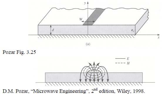
18 Microstrip Transmission Line Cross-section of microstrip geometry. Conductor (A) is separated from ground plane (D) by dielectric substrate (C). Upper dielectric (B) is typically air.[1] Microstrip 90 mitred bend. The percentage mitre is 100x/d [1] [1] Source: Wikipedia
19 Microstrip


20 Design Formulas for Microstrip Pozar Fig Effective permittivity: Speed of travel: Characteristic impedance:

21 Hairpin Filter in Microstrip 25

. Structure is supported by dielectric (C).")
22 Stripline Transmission Line Cross-section diagram of stripline geometry. Central conductor (A) is sandwiched between ground planes (B and D). Structure is supported by dielectric (C). [1] [1] Source: Wikipedia

23 Transmission Line Circuit How do we: Ulaby Fig. 2-5 Account for the capacitance-per-unit-length cc and the inductance-per-unit-length l 1 Account for the speed of travel u = c L Hence account for the time delay T = u Find the voltage at the input and the voltage at the load. 40
24 Typical Response of a Transmission Line Circuit RR ss VV ss VV 0 Transmission Line RR cc, uu RR LL VV LL Parameters: LL V s R s = = step function from 0 to 10 volts starting at t=0 internal resistance of the generator, use 1 ohm L = length of the interconnection path, say 2 cm Z 0 = R c = characteristic resistance of the interconnection path (?????????) Use 50 ohms. u = speed of travel of a voltage on the interconnection path (???????) Use 20 cm/ns R L = input resistance of the load, which is ideally matched (RR LL = RR cc )but for this example we will use a high-resistance load, RR LL = 1000 ohms.
25 Step Response The slide shows one frame from an animation of the response of the circuit, obtained from the BOUNCE program.
26 Questions: What is the physics of this behavior? How does it arise from circuit analysis? How do you solve circuits such as this one? Time domain? Frequency domain? What determines the speed of travel? What is characteristic resistance? How do you design the circuit to avoid this behavior?
Physical Structure of CMOS Integrated Circuits
 Physical Structure of CMOS Integrated Circuits Dae Hyun Kim EECS Washington State University References John P. Uyemura, Introduction to VLSI Circuits and Systems, 2002. Chapter 3 Neil H. Weste and David
2/18/ Transmission Lines and Waveguides 1/3. and Waveguides. Transmission Line A two conductor structure that can support a TEM wave.
 2/18/2009 3 Transmission Lines and Waveguides 1/3 Chapter 3 Transmission Lines and Waveguides First, some definitions: Transmission Line A two conductor structure that can support a TEM wave. Waveguide
Objectives of transmission lines
 Introduction to Transmission Lines Applications Telephone Cable TV (CATV, or Community Antenna Television) Broadband network High frequency (RF) circuits, e.g., circuit board, RF circuits, etc. Microwave
Accurate Power Conversion Measurements on High Power Motor Drives. Presented by: Ian Walker GMW Associates
 Accurate Power Conversion Measurements on High Power Motor Drives Presented by: Ian Walker GMW Associates ian@gmw.com Motor & Drive Systems; January 21, 2016 Interconnections for the test of a low power
Transmission Lines and TDR
 Transmission Lines and TDR Overview This is the procedure for lab 2a. This is a one-week lab. The prelab should be done BEFORE going to the lab session. In this lab, the characteristics of different transmission
Γ L = Γ S =
 TOPIC: Microwave Circuits Q.1 Determine the S parameters of two port network consisting of a series resistance R terminated at its input and output ports by the characteristic impedance Zo. Q.2 Input matching
PATCH ANTENNA DESIGN
 FACULTY OF ELECTRONICS, TELECOMMUNICATIONS, AND INFORMATION TECHNOLOGY Department of Telecommunications and Information Technology Laboratory of Antennas and Propagation Prof. dr. ing. Ion BOGDAN PATCH
Impedance Measurement Handbook
 Impedance Measurement Handbook 1st edition 1 Introduction This handbook describes settings and precautions that apply when using an impedance measuring instrument. Impedance Measurement Handbook 1 Making
ELC 131 CIRCUIT ANALYSIS I
 ELC 131 CIRCUIT ANALYSIS I COURSE DESCRIPTION: Prerequisites: None Corequisites: MAT 121 This course introduces DC and AC electricity with emphasis on circuit analysis, measurements, and operation of test
Exercise problems of topic 1: Transmission line theory and typical waveguides
 Exercise problems of topic 1: Transmission line theory and typical waveguides Return your answers in the contact sessions on a paper; either handwritten or typescripted. You can return them one by one.
Keysight Technologies Techniques for Advanced Cable Testing
 Keysight Technologies Techniques for Advanced Cable Testing Using FieldFox handheld analyzers Application Note Transmission lines are used to guide the flow of energy from one point to another. Line types
Lecture 4. Maximum Transfer of Power. The Purpose of Matching. Lecture 4 RF Amplifier Design. Johan Wernehag Electrical and Information Technology
 Johan Wernehag, EIT Lecture 4 RF Amplifier Design Johan Wernehag Electrical and Information Technology Design of Matching Networks Various Purposes of Matching Voltage-, Current- and Power Matching Design
Units. In the following formulae all lengths are expressed in centimeters. The inductance calculated will be in micro-henries = 10-6 henry.
 INDUCTANCE Units. In the following formulae all lengths are expressed in centimeters. The inductance calculated will be in micro-henries = 10-6 henry. Long straight round wire. If l is the length; d, the
Comparison of cable models for time domain simulations
 24 th Nordic Insulation Symposium on Materials, Components and Diagnostics 158 Comparison of cable models for time domain simulations W.Z. El-Khatib*, J. Holboell*, T.W. Rasmussen* S. Vogel* *Technical
Homework Assignment Consider the circuit shown. Assume ideal op-amp behavior. Which statement below is true?
 Question 1 (2 points each unless noted otherwise) Homework Assignment 03 1. Consider the circuit shown. Assume ideal op-amp behavior. Which statement below is true? (a) V = VV + = 5 V (op-amp operation)
Lab Manual Experiment No. 2
 Lab Manual Experiment No. 2 Aim of Experiment: Observe the transient phenomenon of terminated coaxial transmission lines in order to study their time domain behavior. Requirement: You have to install a
Single-turn and multi-turn coil domains in 3D COMSOL. All rights reserved.
 Single-turn and multi-turn coil domains in 3D 2012 COMSOL. All rights reserved. Introduction This tutorial shows how to use the Single-Turn Coil Domain and Multi-Turn Coil Domain features in COMSOL s Magnetic
Design and Analysis of Circular Ring Micro strip Antenna
 Global Journal of Researches in Engineering Volume 11 Issue 1 Version 1.0 February 2011 Type: Double Blind Peer Reviewed International Research Journal Publisher: Global Journals Inc. (USA) ISSN: 0975-5861
Lecture #3 Microstrip lines
 November 2014 Ahmad El-Banna Benha University Faculty of Engineering at Shoubra Post-Graduate ECE-601 Active Circuits Lecture #3 Microstrip lines Instructor: Dr. Ahmad El-Banna Agenda Striplines Forward
Lecture 4 RF Amplifier Design. Johan Wernehag, EIT. Johan Wernehag Electrical and Information Technology
 Lecture 4 RF Amplifier Design Johan Wernehag, EIT Johan Wernehag Electrical and Information Technology Lecture 4 Design of Matching Networks Various Purposes of Matching Voltage-, Current- and Power Matching
Q. 1 Q. 25 carry one mark each.
 Q. Q. 25 carry one mark each. Q. A random variable XX has probability density function ff(xx) as given below: aa bbbb ffffff 0 < xx < ff(xx) = 0 otherwise If the expected value EE[XX] = 2/3, then PPPP[XX
Precision Measurement
 Precision Measurement Engineering Principles Student Journal Published by ENERGY CONCEPTS, INC. 27201J I COPYRIGHT 2009 BY ENERGY CONCEPTS, INC. All rights reserved. No part of this publication may be
A Simple Wideband Transmission Line Model
 A Simple Wideband Transmission Line Model Prepared by F. M. Tesche Holcombe Dept. of Electrical and Computer Engineering College of Engineering & Science 337 Fluor Daniel Building Box 34915 Clemson, SC
Lesson 10: The Volume of Prisms and Cylinders and Cavalieri s Principle
 : The Volume of Prisms and Cylinders and Cavalieri s Principle Classwork Opening Exercise The bases of the following triangular prism TT and rectangular prism RR lie in the same plane. A plane that is
DETAIL SPECIFICATION SHEET CABLES, RADIO FREQUENCY, SEMIRIGID, COAXIAL, SEMI-AIR-DIELECTRIC,.875 TO INCHES OUTSIDE DIAMETER, 50 OHMS
 INCH-POUND MIL-DTL-22931/11B 21 August 2013 SUPERSEDING MIL-C-22931/11A 20 January 1972 DETAIL SPECIFICATION SHEET CABLES, RADIO FREQUENCY, SEMIRIGID, COAXIAL, SEMI-AIR-DIELECTRIC,.875 TO 1.005 INCHES
from ocean to cloud OPTIMIZATION OF PULSE WIDTH FOR ELECTRIC TDR FOR FAULT POINT LOCALIZATION OF POWER FEEDING LINES OF SUBMARINE CABLES
 OPTIMIZATION OF PULSE WIDTH FOR ELECTRIC TDR FOR FAULT POINT LOCALIZATION OF POWER FEEDING LINES OF SUBMARINE CABLES Junichi Kojima (KDDI R&D Laboratories Inc.) Email: ojima@ddilabs.jp KDDI R&D Laboratories
Intermediate Course (5) Antennas and Feeders
 Antennas and Feeders") Intermediate Course (5) Antennas and Feeders 1 System Transmitter 50 Ohms Output Standing Wave Ratio Meter Antenna Matching Unit Feeder Antenna Receiver 2 Feeders Feeder types: Coaxial, Twin Conductors
Intermediate Course (5) Antennas and Feeders 1 System Transmitter 50 Ohms Output Standing Wave Ratio Meter Antenna Matching Unit Feeder Antenna Receiver 2 Feeders Feeder types: Coaxial, Twin Conductors
Comparative Analysis of Rectangular Waveguide and Coaxial Cable Using H.F.S.S
 Comparative Analysis of Rectangular Waveguide and Coaxial Cable Using H.F.S.S SK Masud Hossain1, Syed Mahammad Ashif1, Subhajit Ghosh1, Diptyajit Das2, Samsur Rahaman3 1Department of Electronics and Communication
ANTENNAS AND PROPAGATION
 TECHNICAL UNIVERSITY GHEORGHE ASACHI OF IAȘI FACULTY OF ELECTRONICS, TELECOMMUNICATIONS, AND INFORMATION TECHNOLOGY Prof. Ion BOGDAN Lecture notes on ANTENNAS AND PROPAGATION 017 C O N T E N T 1. FUNDAMENTALS
CHAPTER 4 EFFECT OF DIELECTRIC COVERS ON THE PERFORMANCES OF MICROSTRIP ANTENNAS 4.1. INTRODUCTION
 CHAPTER 4 EFFECT OF DIELECTRIC COVERS ON THE PERFORMANCES OF MICROSTRIP ANTENNAS 4.1. INTRODUCTION In the previous chapter we have described effect of dielectric thickness on antenna performances. As mentioned
(i) Determine the admittance parameters of the network of Fig 1 (f) and draw its - equivalent circuit.
 Determine the admittance parameters of the network of Fig 1 (f) and draw its - equivalent circuit.") I.E.S-(Conv.)-1995 ELECTRONICS AND TELECOMMUNICATION ENGINEERING PAPER - I Some useful data: Electron charge: 1.6 10 19 Coulomb Free space permeability: 4 10 7 H/m Free space permittivity: 8.85 pf/m Velocity
I.E.S-(Conv.)-1995 ELECTRONICS AND TELECOMMUNICATION ENGINEERING PAPER - I Some useful data: Electron charge: 1.6 10 19 Coulomb Free space permeability: 4 10 7 H/m Free space permittivity: 8.85 pf/m Velocity
APPLIED ELECTROMAGNETICS: EARLY TRANSMISSION LINES APPROACH
 APPLIED ELECTROMAGNETICS: EARLY TRANSMISSION LINES APPROACH STUART M. WENTWORTH Auburn University IICENTBN Nlfll 1807; WILEY 2 OO 7 ; Ttt^TlLtftiTTu CONTENTS CHAPTER1 Introduction 1 1.1 1.2 1.3 1.4 1.5
Microwave and optical systems Introduction p. 1 Characteristics of waves p. 1 The electromagnetic spectrum p. 3 History and uses of microwaves and
 Microwave and optical systems Introduction p. 1 Characteristics of waves p. 1 The electromagnetic spectrum p. 3 History and uses of microwaves and optics p. 4 Communication systems p. 6 Radar systems p.
Waveguides. Metal Waveguides. Dielectric Waveguides
 Waveguides Waveguides, like transmission lines, are structures used to guide electromagnetic waves from point to point. However, the fundamental characteristics of waveguide and transmission line waves
EC TRANSMISSION LINES AND WAVEGUIDES TRANSMISSION LINES AND WAVEGUIDES
 TRANSMISSION LINES AND WAVEGUIDES UNIT I - TRANSMISSION LINE THEORY 1. Define Characteristic Impedance [M/J 2006, N/D 2006] Characteristic impedance is defined as the impedance of a transmission line measured
Lab #2: Electrical Measurements II AC Circuits and Capacitors, Inductors, Oscillators and Filters
 Lab #2: Electrical Measurements II AC Circuits and Capacitors, Inductors, Oscillators and Filters Goal: In circuits with a time-varying voltage, the relationship between current and voltage is more complicated
EE 340 Transmission Lines. Spring 2012
 EE 340 Transmission Lines Spring 2012 Physical Characteristics Overhead lines An overhead transmission line usually consists of three conductors or bundles of conductors containing the three phases of
University of Pennsylvania Department of Electrical and Systems Engineering ESE319
 University of Pennsylvania Department of Electrical and Systems Engineering ESE39 Laboratory Experiment Parasitic Capacitance and Oscilloscope Loading This lab is designed to familiarize you with some
EC 200 CHARACTERISTICS D A T A S H E E T. Kabelwerk EUPEN AG cable. M e c h a n i c a l c h a r a c t e r i s t i c s
 EC 200 EC200 - Rev. 3-23.06.11 Characteristic impedance 50 ± 2 Material copper wire Nominal capacity (pf/m) 80.5 Construction - Relative propagation velocity (%) 83 Diameter (mm) 1.05 Inductance (µh/m)
RF Cavity Design. 1 Introduction the outline of a general cavity design procedure. E. Jensen CERN, Geneva, Switzerland
 RF Cavity Design E. Jensen CERN, Geneva, Switzerland Abstract After a short overview of a general approach to cavity design, we sketch the derivation of waveguide modes from plane waves and of cavity fields
Lesson 16. Opening Exploration A Special Case
 Opening Exploration A Special Case 1. Consuela ran across the quadratic equation y = 4x 2 16 and wondered how it could be factored. She rewrote it as y = 4x 2 + 0x 16. A. Use one of the methods you ve
SECTION 4: TRANSMISSION LINES. ESE 470 Energy Distribution Systems
 SECTION 4: TRANSMISSION LINES ESE 470 Energy Distribution Systems 2 Introduction Transmission Lines 3 Transmission and distribution of electrical power occurs over metal cables Overhead AC or DC Underground
L-BAND COPLANAR SLOT LOOP ANTENNA FOR INET APPLICATIONS
 L-BAND COPLANAR SLOT LOOP ANTENNA FOR INET APPLICATIONS Jeyasingh Nithianandam Electrical and Computer Engineering Department Morgan State University, 500 Perring Parkway, Baltimore, Maryland 5 ABSTRACT
ARNSW Balun Day. Balun construction
 ARNSW Balun Day Balun construction Typical Baluns All built from locally available components. Balun uses Most baluns are used to match the 50Ω output of a transceiver to an antenna. A centre fed dipole
TABLE OF CONTENTS 1 Fundamentals Transmission Line Parameters... 29
 TABLE OF CONTENTS 1 Fundamentals... 1 1.1 Impedance of Linear, Time-Invariant, Lumped-Element Circuits... 1 1.2 Power Ratios... 2 1.3 Rules of Scaling... 5 1.3.1 Scaling of Physical Size... 6 1.3.1.1 Scaling
University of KwaZulu-Natal
 University of KwaZulu-Natal School of Engineering Electrical, Electronic & Computer Engineering UNIVERSITY EXAMINATIONS NOVEMBER 2015 ENEL3EM: EM THEORY Time allowed: 2 hours Instructions to Candidates:
Photograph of the rectangular waveguide components
 Waveguides Photograph of the rectangular waveguide components BACKGROUND A transmission line can be used to guide EM energy from one point (generator) to another (load). A transmission line can support
7. Experiment K: Wave Propagation
 7. Experiment K: Wave Propagation This laboratory will be based upon observing standing waves in three different ways, through coaxial cables, in free space and in a waveguide. You will also observe some
Demystifying Vias in High-Speed PCB Design
 Demystifying Vias in High-Speed PCB Design Keysight HSD Seminar Mastering SI & PI Design db(s21) E H What is Via? Vertical Interconnect Access (VIA) An electrical connection between layers to pass a signal
Pulse Transmission and Cable Properties ================================
 PHYS 4211 Fall 2005 Last edit: October 2, 2006 T.E. Coan Pulse Transmission and Cable Properties ================================ GOAL To understand how voltage and current pulses are transmitted along
Lecture - 14 Microwave Resonator
 Basic Building Blocks of Microwave Engineering Prof Amitabha Bhattacharya Department of Electronics and Communication Engineering Indian Institute of Technology, Kharagpur Lecture - 14 Microwave Resonator
Telecommunication Wiring Questions
 Telecommunication Wiring Questions 1. is the process of modifying a carrier frequency in rhythm to the audio frequency. A, Modulation B. Amplitude C. Change of phase D. Interference 2. is the property
b) discrete-time iv) aperiodic (finite energy)
 discrete-time iv) aperiodic (finite energy)") EE 464 Frequency Analysis of Signals and Systems Fall 2018 Read Text, Chapter. Study suggestion: Use Matlab to plot several of the signals and their DTFT in the examples to follow. Some types of signal
EE 464 Frequency Analysis of Signals and Systems Fall 2018 Read Text, Chapter. Study suggestion: Use Matlab to plot several of the signals and their DTFT in the examples to follow. Some types of signal
Microwave Engineering
 Microwave Circuits 1 Microwave Engineering 1. Microwave: 300MHz ~ 300 GHz, 1 m ~ 1mm. a. Not only apply in this frequency range. The real issue is wavelength. Historically, as early as WWII, this is the
EE 740 Transmission Lines
 EE 740 Transmission Lines 1 High Voltage Power Lines (overhead) Common voltages in north America: 138, 230, 345, 500, 765 kv Bundled conductors are used in extra-high voltage lines Stranded instead of
x16 GAZEBO ASSEMBLY INSTRUCTIONS
 36 1 x16 GAZEBO ASSEMBLY INSTRUCTIONS Assembly with more than one person recommended 0 L:\WP51\Instructions\SOLARIUMS INSTRUCTION BOOKS\36\ZZZ-05.36.0810-1.GP.EN.doc Step 1: Assemble beams A and B using
x12 GAZEBO ASSEMBLY INSTRUCTIONS
 30 10 x1 GAZEBO ASSEMBLY INSTRUCTIONS Assembly with more than one person recommended 0 L:\WP51\Instructions\SOLARIUMS INSTRUCTION BOOKS\30\ZZZ-0.30.0807-1.GP.EN.doc Step 1: Assemble beams A and B using
12 X 18 SOLARIUM ASSEMBLY INSTRUCTIONS
 1218 12 X 18 SOLARIUM ASSEMBLY INSTRUCTIONS Assembly by more than one person is recommended. Base Dimensions 12 ½ x18 11, Largest Dimensions 13 6 x20 ½ (see pg.1) L:\WP51\Instructions\SOLARIUMS INSTRUCTION
電子回路論第 7 回 Electric Circuits for Physicists #7
 電子回路論第 7 回 Electric Circuits for Physicists #7 東京大学理学部 理学系研究科物性研究所勝本信吾 Shingo Katsumoto Outline 4.5 Field Effect Transistors (FETs) Ch.5 Distributed constant circuits 5.1 Transmission lines 5.1.1 Coaxial
Radio Frequency Electronics
 Radio Frequency Electronics Preliminaries II Guglielmo Giovanni Maria Marconi Thought off by many people as the inventor of radio Pioneer in long-distance radio communications Shared Nobel Prize in 1909
Projects in microwave theory 2009
 Electrical and information technology Projects in microwave theory 2009 Write a short report on the project that includes a short abstract, an introduction, a theory section, a section on the results and
PRELIMINARIES. Generators and loads are connected together through transmission lines transporting electric power from one place to another.
 TRANSMISSION LINES PRELIMINARIES Generators and loads are connected together through transmission lines transporting electric power from one place to another. Transmission line must, therefore, take power
Speedflex. Halogen free coaxial cables.
 Speedflex Halogen free coaxial cables Speedflex is a completely halogen-free and environmentally-friendly alternative to standard RG coaxial cables. Speedflex Item Material Speedflex Speedflex Speedflex
C.2 Equations and Graphs of Conic Sections
 0 section C C. Equations and Graphs of Conic Sections In this section, we give an overview of the main properties of the curves called conic sections. Geometrically, these curves can be defined as intersections
12 X 18 SOLARIUM ASSEMBLY INSTRUCTIONS
 adlonco@hotmail.com 1218 12 X 18 SOLARIUM ASSEMBLY INSTRUCTIONS Assembly by more than one person is recommended. Base Dimensions 12 ½ x18 11, Largest Dimensions 13 6 x20 ½ (see pg.1) ZZZ-18.1218.0530-1.GP.EN.HER.doc
INTRODUCTION OF WAVEGUIDES
 INTRODUCTION OF WAVEGUIDES Under guidance of Joydeep Sengupta sir VNIT BT14ECE031 CHARAN SAI KATAKAM 1 INTRODUCTION TO WAVEGUIDES In a waveguide energy is transmitted in the form of electromagnetic waves
Summer Homework. Trace each number. Count to 10. Complete the picture. Tell a story about your picture..
 Week 1 {June 4} Read every day! Parent Initial Week 2 {June 11} Read every day! Parent Initial June Summer Homework Monday Tuesday Wednesday Thursday Trace the letters. Color each of the pictures. Match
Lab 1: Pulse Propagation and Dispersion
 ab 1: Pulse Propagation and Dispersion NAME NAME NAME Introduction: In this experiment you will observe reflection and transmission of incident pulses as they propagate down a coaxial transmission line
CHAPTER 2. Basic Concepts, Three-Phase Review, and Per Unit
 CHAPTER 2 Basic Concepts, Three-Phase Review, and Per Unit 1 AC power versus DC power DC system: - Power delivered to the load does not fluctuate. - If the transmission line is long power is lost in the
Problems in Electromagnetics, Vol. 1 Version 1.1. Steven W. Ellingson Virginia Tech
 Problems in Electromagnetics, Vol. 1 Version 1.1 Steven W. Ellingson ellingson.1@vt.edu Virginia Tech August 10, 2018 This manual accompanies Electromagnetics Vol. 1, an open textbook freely available
Exercise 1-2. Velocity of Propagation EXERCISE OBJECTIVE
 Exercise 1-2 Velocity of Propagation EXERCISE OBJECTIVE Upon completion of this unit, you will know how to measure the velocity of propagation of a signal in a transmission line, using the step response
CITY UNIVERSITY OF HONG KONG
 CITY UNIVERSITY OF HONG KONG Modeling and Analysis of the Planar Spiral Inductor Including the Effect of Magnetic-Conductive Electromagnetic Shields Submitted to Department of Electronic Engineering in
Monoconical RF Antenna
 Page 1 of 8 RF and Microwave Models : Monoconical RF Antenna Monoconical RF Antenna Introduction Conical antennas are useful for many applications due to their broadband characteristics and relative simplicity.
Lect2: EM Radio Waves and Antenna Operation
 Lect2: EM Radio Waves and Antenna Operation Dr. Yazid Khattabi Communication Systems Course EE Department University of Jordan 2018 Dr. Yazid Khattabi. The University of Jordan. 1 EM Radio Waves In wireless
The Three Most Confusing Topics in Signal Integrity
 Slide -1 The Three Most Confusing Topics in Signal Integrity and how not to be confused with Dr. Eric Bogatin, Signal Integrity Evangelist, Bogatin Enterprises, www.bethesignal.com eric@bethesignal.com
Project 6 Capacitance of a PN Junction Diode
 Project 6 Capacitance of a PN Junction Diode OVERVIEW: In this project, we will characterize the capacitance of a reverse-biased PN diode. We will see that this capacitance is voltage-dependent and we
Microwave Circuits 1.1 INTRODUCTION
 Microwave Circuits 1.1 INTRODUCTION The term microwave circuits means different things to different people. The prefix micro comes from the Greek fiikpog (micros) and among its various meanings has the
Introduction: Planar Transmission Lines
 Chapter-1 Introduction: Planar Transmission Lines 1.1 Overview Microwave integrated circuit (MIC) techniques represent an extension of integrated circuit technology to microwave frequencies. Since four
EC Transmission Lines And Waveguides
 EC6503 - Transmission Lines And Waveguides UNIT I - TRANSMISSION LINE THEORY A line of cascaded T sections & Transmission lines - General Solution, Physical Significance of the Equations 1. Define Characteristic
EE 340 Transmission Lines
 EE 340 Transmission Lines Physical Characteristics Overhead lines An overhead transmission line usually consists of three conductors or bundles of conductors containing the three phases of the power system.
Designs of Substrate Integrated Waveguide (SIW) and Its Transition to Rectangular Waveguide. Ya Guo
 and Its Transition to Rectangular Waveguide. Ya Guo") Designs of Substrate Integrated Waveguide (SIW) and Its Transition to Rectangular Waveguide by Ya Guo A thesis submitted to the Graduate Faculty of Auburn University in partial fulfillment of the requirements
Designs of Substrate Integrated Waveguide (SIW) and Its Transition to Rectangular Waveguide by Ya Guo A thesis submitted to the Graduate Faculty of Auburn University in partial fulfillment of the requirements
Amplifiers and Feedback Theory. Alessandro Spinelli Phone: ( ) 4001 home.deib.polimi.
 4001 home.deib.polimi.") Amplifiers and Feedback Theory Phone: (02 2399) 4001 alessandro.spinelli@polimi.it home.deib.polimi.it/spinelli Slides are supplementary material and are NOT a replacement for textbooks and/or lecture
Amplifiers and Feedback Theory Phone: (02 2399) 4001 alessandro.spinelli@polimi.it home.deib.polimi.it/spinelli Slides are supplementary material and are NOT a replacement for textbooks and/or lecture
University of KwaZulu-Natal
 University of KwaZulu-Natal School of Engineering Electrical, Electronic & Computer Engineering Instructions to Candidates: UNIVERSITY EXAMINATIONS DECEMBER 2016 ENEL3EM: EM THEORY Time allowed: 2 hours
The performance of AM and FM receivers. Editor: Xuanfeng Li Teacher: Prof. Xiliang Luo
 The performance of AM and FM receivers Editor: Xuanfeng Li Teacher: Prof. Xiliang Luo The performance of AM receivers using Envelop Detection In a full AM signal, both sidebands and the carrier wave are
A Coherent Technical Note August 29, Propagation, Dispersion and Measurement of sub-10 fs Pulses. Table of Contents
 Propagation, Dispersion and Measurement of sub-10 fs Pulses Table of Contents 1. Theory 2. Pulse propagation through various materials o Calculating the index of refraction Glass materials Air Index of
S-Link. RF Cable Solution
 S-Link RF Cable Solution Netop supplys complete RF subsystem for site application with Rosenberger S-Link site solution package which include feeder cables, jumpers, connectors, surge arresters, grounding
Efficient Electromagnetic Analysis of Spiral Inductor Patterned Ground Shields
 Efficient Electromagnetic Analysis of Spiral Inductor Patterned Ground Shields James C. Rautio, James D. Merrill, and Michael J. Kobasa Sonnet Software, North Syracuse, NY, 13212, USA Abstract Patterned
SPONSORED BY 1 MARCH Illustrations Jim Field. Photography Simon Webb DESIGN GUIDELINES
 SPONSORED BY 1 MARCH 2018 Illustrations Jim Field. Photography Simon Webb. 2018 DESIGN GUIDELINES World Book Day is the biggest celebration of books and reading in the world. This toolkit outlines how
DESIGN AND FABRICATION OF CAVITY RESONATORS
 &2@?%3 DESIGN AND FABRICATION OF CAVITY RESONATORS CHAPTER 3 DESIGN AND FABRICATION OFCAVITY RESONATORS 3.1 Introduction In the cavity perturbation techniques, generally rectangular or cylindrical waveguide
ECE 145A/218A, Lab Project #1b: Transistor Measurement.
 ECE 145A/218A, Lab Project #1b: Transistor Measurement. September 28, 2017 OVERVIEW... 2 GOALS:... 2 SAFETY PRECAUTIONS:... 2 READING:... 2 TRANSISTOR RF CHARACTERIZATION.... 3 DC BIAS CIRCUITS... 3 TEST
Cray Valley Radio Society. Real Life Wire Antennas
 Cray Valley Radio Society Real Life Wire Antennas 1 The basic dipole The size of an antenna is determined by the wavelength of operation In free space: ~3x10 8 m/s Frequency x Wavelength = Speed of Light,
AM BASIC ELECTRONICS TRANSMISSION LINES JANUARY 2012 DEPARTMENT OF THE ARMY MILITARY AUXILIARY RADIO SYSTEM FORT HUACHUCA ARIZONA
 AM 5-306 BASIC ELECTRONICS TRANSMISSION LINES JANUARY 2012 DISTRIBUTION RESTRICTION: Approved for Pubic Release. Distribution is unlimited. DEPARTMENT OF THE ARMY MILITARY AUXILIARY RADIO SYSTEM FORT HUACHUCA
Advanced Microeconomic Theory. Chapter 10: Contract Theory
 Advanced Microeconomic Theory Chapter 10: Contract Theory Outline Moral Hazard Moral Hazard with a Continuum of Effort Levels The First-Order Approach Moral Hazard with Multiple Signals Adverse Selection
Lines and Slotlines. Microstrip. Third Edition. Ramesh Garg. Inder Bahl. Maurizio Bozzi ARTECH HOUSE BOSTON LONDON. artechhouse.
 Microstrip Lines and Slotlines Third Edition Ramesh Garg Inder Bahl Maurizio Bozzi ARTECH HOUSE BOSTON LONDON artechhouse.com Contents Preface xi Microstrip Lines I: Quasi-Static Analyses, Dispersion Models,
Analysis of a PCB-Chassis System Including Different Sizes of Multiple Planes Based on SPICE
 Analysis of a PCB-Chassis System Including Different Sizes of Multiple Planes Based on SPICE Naoki Kobayashi (1), Todd Hubing (2) and Takashi Harada (1) (1) NEC, System Jisso Research Laboratories, Kanagawa,
CAT. 5e U/UTP 4x2x24AWG/1 CCA DOUBLE SHEATH
 CAT. 5e U/UTP 4x2x24AWG/1 CCA DOUBLE SHEATH FIGURE CONSTRUCTION Inner conductor CCA Φ 0.50±0.01mm Insulation Solid HDPE Φ 0.90±0.05mm Color 1 Blue & White/ Blue 2 Orange & White/ Orange 3 Green & White/
International Journal of Advanced Research in Computer Engineering &Technology (IJARCET) Volume 2, Issue 4, April 2013
 Volume 2, Issue 4, April 2013") Surface and Embedded Micro Strip Lines Characteristic Impedance and its Signal Propagation Delay Time in Optical Spectrum Transmission Regions Ahmed Nabih Zaki Rashed Electronics and Electrical Communications
Surface and Embedded Micro Strip Lines Characteristic Impedance and its Signal Propagation Delay Time in Optical Spectrum Transmission Regions Ahmed Nabih Zaki Rashed Electronics and Electrical Communications
ECE 145A/218A, Lab Project #1a: passive Component Test.
 ECE 145A/218A, Lab Project #1a: passive Component Test. September 28, 2017 OVERVIEW... 2 GOALS:... 2 PRECAUTIONS TO AVOID INSTRUMENT DAMAGE... 2 SAFETY PRECAUTIONS... 2 READING:... 3 NETWORK ANALYZER CALIBRATION...
Magnetic Response of Rectangular and Circular Split Ring Resonator: A Research Study
 Magnetic Response of Rectangular and Circular Split Ring Resonator: A Research Study Abhishek Sarkhel Bengal Engineering and Science University Shibpur Sekhar Ranjan Bhadra Chaudhuri Bengal Engineering
Generation of Sub-nanosecond Pulses
 Chapter - 6 Generation of Sub-nanosecond Pulses 6.1 Introduction principle of peaking circuit In certain applications like high power microwaves (HPM), pulsed laser drivers, etc., very fast rise times