Single-turn and multi-turn coil domains in 3D COMSOL. All rights reserved.
|
|
|
- Peregrine Atkins
- 5 years ago
- Views:
Transcription

1 Single-turn and multi-turn coil domains in 3D 2012 COMSOL. All rights reserved.
2 Introduction This tutorial shows how to use the Single-Turn Coil Domain and Multi-Turn Coil Domain features in COMSOL s Magnetic Fields interface for modeling coils in 3D These features are available only with the AC/DC Module They are suitable for computationally efficient modeling of current-carrying conductors creating magnetic field Additional information related to suitability of using these coil modeling features in DC and AC are provided
3 When modeling magnetic field, we need to have a closed current loop Use a closed geometry Specify a closed current path using appropriate modeling techniques
4 When modeling magnetic field, we need to have a closed current loop Use appropriate boundary conditions for open geometries
5 Overview This tutorial describes how to use the following features Single-turn coil domain Gap feed Boundary feed Multi-turn coil domain Linear coil Circular coil Numeric coil Using symmetry User-defined coil
6 Single-turn coil domain Model the actual conductor to compute magnitude and direction of current flow Use this information to find the magnetic field in and around the conductor Useful when you have a few turns Also when you want to resolve the current distribution in individual wires and turns Single-turn toroidal coil Note:You need to model an air domain around the conductor
7 Modeling in frequency domain -AC Always use this when the signal is periodic (e.g. sinusoidal, square wave) Can be used for single-turn coil domain as long as the skin depth is not too small compared to the conductor thickness When the skin depth is smaller than the conductor thickness, use a boundary layer mesh When the skin depth is significantly smaller (< 1/20 th ) than the conductor thickness then we cannot use single-turn coil domain anymore
8 Modeling in time domain -Transient Cannot be used for single-turn coil domain COMSOL uses an A-V formulation locally within the single-turn coil Solves for both magnetic vector potential (A) and electric potential (V) Transient simulation is not supported for such cases because V is not uniquely defined at each point in space In time domain analysis, the voltage (V) is defined as a path integral between two points in space For details on the A-V formulation, refer to the AC/DC Module User s Guide

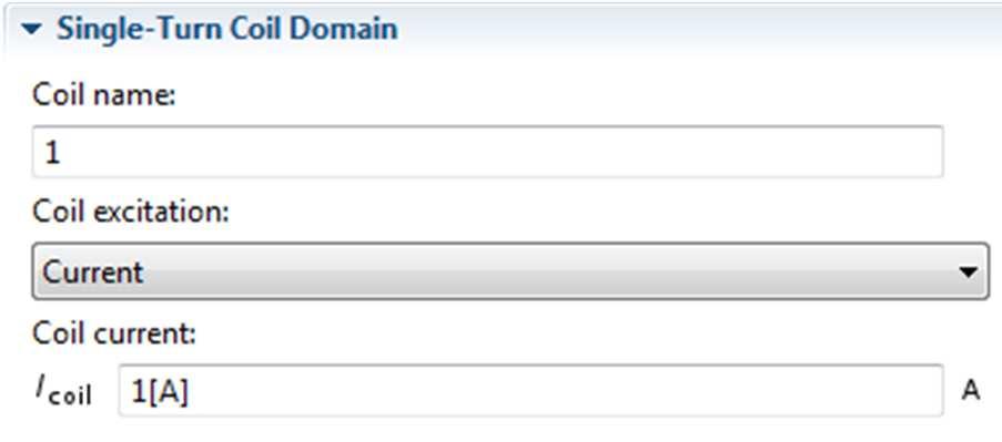
9 Single-turn coil Gap feed Single-turn coil Leads are not modeled Geometry must form a closed loop Cross section and shape can be arbitrary
10 Coil excitation method Excitation source is modeled as an internal cross section boundary called gap feed We need to be careful while drawing the geometry so that we create this internal boundary Gap feed 1. Specify the voltage across this boundary 2. Specify the current through this boundary 3. Options to connect to lumped electrical circuit
11 Modeling in COMSOL For detailed modeling steps, see the following file: single_coil_gap_feed.mph This model shows both DC and AC cases
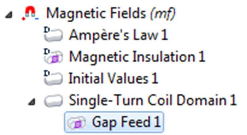
12 Using single-turn coil domain with gap feed
 Inductance = 1.")
13 Results Magnetic flux density (DC) Inductance = 1.17e-8 H
")
14 Results Current density DC solution Resistance = 1.65e-4 Ω Higher current density along the inner radius indicates that more current is concentrated along a shorter conduction path AC (20 khz) solution Impedance = 2.36e i Ω Current distribution clearly shows the skin effect
15 Using gap feed in AC single-turn coil Gap feed in AC indicates a connection to a transmission line In reality there is a capacitive coupling between the two ends of this gap feed Capacitive coupling is more significant at higher frequencies We cannot model it since we assume the gap feed to be a zero thickness surface Gap impedance will depend on the actual gap thickness and material property of the gap Gap feed is perfectly accurate for DC models but a good approximation only for low frequency AC models

16 Single-turn coil Boundary feed Single-turn coil Leads are modeled Geometry does not form a closed loop Cross section and shape can be arbitrary You can use this to model more than a single turn
17 Coil excitation method Direction of current flow is modeled by specifying a ground surface and a boundary feed These surfaces should touch the external walls of the air domain surrounding the conductor Boundary feed 1. Specify the voltage at this boundary 2. Specify the current through this boundary 3. Options to connect to lumped electrical circuit Ground
18 Modeling in COMSOL For detailed modeling steps, see the following file: single_coil_boundary_feed.mph This model shows both DC and AC cases


19 Using single-turn coil domain with ground and boundary feed


20 Results Magnetic flux density (DC) Inductance = 3.16e-8 H
")
21 Results Current density DC solution Resistance = 3.25e-4 Ω Higher current density along the inner edges indicates that more current is concentrated along a shorter conduction path AC (20 khz) solution Impedance = 4.79e i Ω Current distribution clearly shows the skin effect

22 Meshing considerations Default free tetrahedral mesh is suitable for the DC problem Boundary layer mesh is better to resolve the skin effect for AC problems where the skin depth is smaller than the conductor cross section


23 Resolving the skin effect in conductors using boundary layer mesh Compute skin depth: δ = 2 ωµσ If the skin depth is less than ½ the thickness of the conductor, consider using a boundary layer mesh Two layers of mesh around the conductor wall is good enough Each layer has the same thickness as the skin depth

24 Multi-turn coil domain Model a homogenized current carrying region to compute magnitude and direction of current flow Use this information to find the magnetic field in and around the conductor Useful when you have a lot of turns Each individual wire is insulated hence no shorting between conductors Individual wire and multiple layers are not resolved Homogenized multi-turn coil Note:You still need to model an air domain around the conductor
25 Modeling in frequency and time domain Always use frequency domain when the signal is periodic (e.g. sinusoidal, square wave) Linear problem Relatively easy to solve Can be used for multi-turn coil domain as long as the skin depth is much larger than the individual wire diameter Use time domain only if the signal is not periodic (e.g. pulse) Nonlinear problem Requires more computational time and memory

26 Convergence tips when using 3D Multi-Turn Coil Domain in frequency domain models Use a small non-zero electrical conductivity for Air This is required to avoid creating a singular stiffness matrix A value of 1[S/m] is a good guess Using smaller values would increase computation time Cannot use a very high value because that would affect the physics of the model May need Gauge fixing Add Gauge Fixing to Ampere s Law Add Gauge Fixing to Multi-Turn Coil Domain Required to get a unique numerical solution

27 Multi-turn coil Linear Multiple parallel straight wires bundled in a sleeve Leads are modeled Geometry should not form a closed loop and must have a straight longitudinal axis Cross section can be arbitrary

28 Coil excitation method Direction of current flow is modeled by specifying a reference edge Also the two end surfaces should touch the external walls of the air domain surrounding the conductor Reference edge
29 Modeling in COMSOL For detailed modeling steps, see the following file: multi_coil_linear.mph This model shows only the DC case

30 Using multi-turn coil domain: Linear

31 Note on coil properties This is the electrical conductivity of the wire material This is the cross section area of each wire COMSOL uses these for computing coil resistance The relative permeability and relative permittivity values are for the homogenized coil domain

32 Options for wire cross section Default is set to User defined cross section area Can specify the wire diameter of round wire Can also specify AWG or SWG number Note: We are still not geometrically resolving the wires

33 Results Magnetic flux density Inductance = 1.02e-6 H


34 Results Current density Resistance = Ω

35 Multi-turn coil Circular Multiple wires arranged as a circular coil and placed in a potting material Leads are not modeled Geometry must form a closed loop and must have a straight longitudinal axis Cross section must be circular
 that should form a closed curve")
36 Coil excitation method Direction of current flow is modeled by specifying a reference edge(typically more than one edge) that should form a closed curve Reference edges
37 Modeling in COMSOL For detailed modeling steps, see the following file: multi_coil_circular.mph This model shows both DC and AC cases The AC model shows the effect of induced current in a conductor placed in the AC magnetic field created by the multiturn coil

38 Using multi-turn coil domain: Circular
39 Results Magnetic flux density (DC) Inductance = 6.04e-6 H
 solution")

40 Results Current density DC solution Resistance = Ω Uniform current density in the homogenized coil domain AC (100 Hz) solution Impedance = i Ω Uniform current density in coil domain but skin effect is visible in the copper core The arrows show that the current direction is opposite in the coil and the core because of induction effect
41 Note on reference edge For circular coil, the reference edge is used for: Defining the current direction Defining the total length (L) of the wire where: L 1 dl = reference edge The effective coil resistance (R) is computed as: NL R = σ coil A coil N = number of turns σ coil = electrical conductivity of wires A coil = cross-section area of individual wire


42 Choice of reference edge Choice of reference edge can affect the accuracy of computed coil resistance if the cross section is appreciably thick Choosing a set of edges which run through the middle of the thickness will give a better estimate of resistance Choosing a set of edges which run around the outer or inner periphery will give an overestimate or underestimate respectively of resistance

43 Multi-turn coil Numeric Multiple wires arranged as a coil and placed in a potting material Leads are not modeled Geometry must form a closed loop Cross section can have arbitrary shape Preferable not to have sharp corners in the cross section Use fillets

44 Coil excitation method Excitation source is modeled as an internal cross section boundary called an Input Need to take care while drawing the geometry so that we create this internal boundary Other boundaries of the multi-turn coil domain should be assigned to Electric insulation Current flows parallel to these surfaces Need to add a Coil Current Calculation study step Input
45 Modeling in COMSOL For detailed modeling steps, see the following file: multi_coil_numeric.mph This model shows the DC case

46 Using multi-turn coil domain: Numeric

47 Study settings for numeric multi-turn coil Add this step manually from Study 1 > Study Steps Drag this step up and ensure that it is located abovestep 2: Stationaryunder the Study branch COMSOL will automatically setup the appropriate solvers An eigenvalue solver will first compute the direction of current flow in the coil domain This information will be then used in the stationary solver


48 Results Magnetic flux density Inductance = 3.87e-6 H


49 Results Current density xy-view Resistance = Ω


50 Using symmetry ½ model Coil resistance and inductance is 2 times the computed value Need to use three boundary conditions for a numeric multi-turn coil domain Electric insulation: current is parallel to these surfaces Input: inlet surface for current flow Output: outlet surface for current flow Input Output
51 Modeling in COMSOL For detailed modeling steps, see the following file: multi_coil_numeric_symmetry_half.mph This model shows the DC case

52 Using multi-turn coil domain: Numeric All other settings are identical to the full 3D model
53 Results Magnetic flux density Inductance = 3.86e-6 H


54 Results Current density xy-view Resistance = Ω


55 Using symmetry 1/8 th model Coil resistance and inductance is 8 times the computed value Need to use three boundary conditions for a numeric multi-turn coil domain Electric insulation: current is parallel to these surfaces Input: inlet surface for current flow Output: outlet surface for current flow Input Output
56 Modeling in COMSOL For detailed modeling steps, see the following file: multi_coil_numeric_symmetry_octant.mph This model shows the DC case


57 Using multi-turn coil domain: Numeric Use half the number of turns since we have cut the geometry by half along the length of the coil

58 Results Magnetic flux density Inductance = 3.86e-6 H


59 Results Current density Resistance = Ω

60 Note on cross section area Longitudinal cross-section area must be constant Coil Current Calculation study computes the local current direction It will not compute the local crosssection area This information is obtained from the area of the input boundary This means that current will not be conserved if the coil cross-sectional area changes along the current path A A B B Sections AA and BB have significantly different cross section area
61 Which coil modeling option to choose? The Linear and Circular coil options are special cases You can use the Numericcoil option to model linear or circular coils Remember to add a Coil Current Calculation study whenever you use a Numeric coil

62 Multi-turn coil User defined For general case Geometry need to form a closed loop Need to specify coil length Specify current direction using vectors Could be a function of x, y and z coordinates We need to ensure that the current direction creates a closed loop Do notneed to add a Coil Current Calculation study step
63 Summary This tutorial showed how to use the 3D single-turn and multi-turn coil domain features New modeling features Gap feed, Boundary feed, Reference edge, Input, Output Considerations while drawing geometry Need to create additional internal boundary for Single-turn coil domain with Gap feed and Numeric type Multi-turn coil domain Study set up Coil Current Calculation study required only for Numeric type Multi-turn coil domain DC vs. AC Meshing Convergence tips
Maximizing the Fatigue Crack Response in Surface Eddy Current Inspections of Aircraft Structures
 Maximizing the Fatigue Crack Response in Surface Eddy Current Inspections of Aircraft Structures Catalin Mandache *1, Theodoros Theodoulidis 2 1 Structures, Materials and Manufacturing Laboratory, National
Inductive Conductivity Measurement of Seawater
 Inductive Conductivity Measurement of Seawater Roger W. Pryor, Ph.D. Pryor Knowledge Systems *Corresponding author: 498 Malibu Drive, Bloomfield Hills, MI, 48302-223, rwpryor@pksez.com Abstract: Approximately
R. W. Erickson. Department of Electrical, Computer, and Energy Engineering University of Colorado, Boulder
 R. W. Erickson Department of Electrical, Computer, and Energy Engineering University of Colorado, Boulder 13.2.3 Leakage inductances + v 1 (t) i 1 (t) Φ l1 Φ M Φ l2 i 2 (t) + v 2 (t) Φ l1 Φ l2 i 1 (t)
Transient Finite Element Analysis of a SPICE-coupled Transformer with COMSOL Multiphysics
 Excerpt from the Proceedings of the COMSOL Conference 200 Paris Transient Finite Element Analysis of a SPICE-coupled Transformer with COMSOL Multiphysics T. Bödrich *, H. Neubert, and R. Disselnötter 2
Lab E2: B-field of a Solenoid. In the case that the B-field is uniform and perpendicular to the area, (1) reduces to
 reduces to") E2.1 Lab E2: B-field of a Solenoid In this lab, we will explore the magnetic field created by a solenoid. First, we must review some basic electromagnetic theory. The magnetic flux over some area A is
E2.1 Lab E2: B-field of a Solenoid In this lab, we will explore the magnetic field created by a solenoid. First, we must review some basic electromagnetic theory. The magnetic flux over some area A is
Advanced Meshing Techniques
 Advanced Meshing Techniques Ansoft High Frequency Structure Simulator v10 Training Seminar P-1 Overview Initial Mesh True Surface Approximation Surface Approximation Operations Lambda Refinement Seeding
A Numerical Study of Depth of Penetration of Eddy Currents
 A Numerical Study of Depth of Penetration of Eddy Currents S.Majidnia* a,b, R.Nilavalan b, J. Rudlin a a. TWI Ltd, Cambridge,United Kingdom b Brunel University, London,United Kingdom shiva.majidnia@twi.co.uk
R. W. Erickson. Department of Electrical, Computer, and Energy Engineering University of Colorado, Boulder
 R. W. Erickson Department of Electrical, Computer, and Energy Engineering University of Colorado, Boulder 13.3.2 Low-frequency copper loss DC resistance of wire R = ρ l b A w where A w is the wire bare
(c) In the process of part (b), must energy be supplied to the electron, or is energy released?
 In the process of part (b), must energy be supplied to the electron, or is energy released?") (1) A capacitor, as shown, has plates of dimensions 10a by 10a, and plate separation a. The field inside is uniform, and has magnitude 120 N/C. The constant a equals 4.5 cm. (a) What amount of charge is
(1) A capacitor, as shown, has plates of dimensions 10a by 10a, and plate separation a. The field inside is uniform, and has magnitude 120 N/C. The constant a equals 4.5 cm. (a) What amount of charge is
Units. In the following formulae all lengths are expressed in centimeters. The inductance calculated will be in micro-henries = 10-6 henry.
 INDUCTANCE Units. In the following formulae all lengths are expressed in centimeters. The inductance calculated will be in micro-henries = 10-6 henry. Long straight round wire. If l is the length; d, the
FERRITE CORE INDUCTOR VALUE VARIATION WITH NUMBER OF TURNS AND DIAMETER OF COPPER WIRE,LENGTH AND DIAMETER OF CORE
 FERRITE CORE INDUCTOR VALUE VARIATION WITH NUMBER OF TURNS AND DIAMETER OF COPPER WIRE,LENGTH AND DIAMETER OF CORE PRJ. NO. 073 PRESENTED BY: OMWENGA EDWIN NYAKUNDI F17/8280/2004 SUPERVISOR : MR. OGABA
Accurate Models for Spiral Resonators
 MITSUBISHI ELECTRIC RESEARCH LABORATORIES http://www.merl.com Accurate Models for Spiral Resonators Ellstein, D.; Wang, B.; Teo, K.H. TR1-89 October 1 Abstract Analytically-based circuit models for two
ELECTROMAGNETIC INDUCTION AND ALTERNATING CURRENT (Assignment)
") ELECTROMAGNETIC INDUCTION AND ALTERNATING CURRENT (Assignment) 1. In an A.C. circuit A ; the current leads the voltage by 30 0 and in circuit B, the current lags behind the voltage by 30 0. What is the
ELECTROMAGNETIC INDUCTION AND ALTERNATING CURRENT (Assignment) 1. In an A.C. circuit A ; the current leads the voltage by 30 0 and in circuit B, the current lags behind the voltage by 30 0. What is the
AP Physics C. Alternating Current. Chapter Problems. Sources of Alternating EMF
 AP Physics C Alternating Current Chapter Problems Sources of Alternating EMF 1. A 10 cm diameter loop of wire is oriented perpendicular to a 2.5 T magnetic field. What is the magnetic flux through the
Numerical Simulation of PCB-Coil-Layouts for Inductive Energy Transfer
 Numerical Simulation of PCB-Coil-Layouts for Inductive Energy Transfer Systems David Maier *, Normen Lucht, Alexander Enssle, Anna Lusiewicz, Julian Fischer, Urs Pecha, Prof. Dr.-Ing. Nejila Parspour University
AIR-CORE MEASURING DEJANA HERCEG FACULTY OF TECHNICAL SCIENCES UNIVERSITY OF NOVI SAD, SERBIA. COMSOL Conference 2010 Paris
 Presented at the COMSOL Conference 2010 Paris PARAMETRIC MODEL OF AN AIR-CORE MEASURING TRANSFORMER DEJANA HERCEG FACULTY OF TECHNICAL SCIENCES UNIVERSITY OF NOVI SAD, SERBIA COMSOL Conference 2010 Paris
total j = BA, [1] = j [2] total
![total j = BA, [1] = j [2] total](/thumbs/85/91692343.jpg "total j = BA, [1] = j [2] total") Name: S.N.: Experiment 2 INDUCTANCE AND LR CIRCUITS SECTION: PARTNER: DATE: Objectives Estimate the inductance of the solenoid used for this experiment from the formula for a very long, thin, tightly wound
Name: S.N.: Experiment 2 INDUCTANCE AND LR CIRCUITS SECTION: PARTNER: DATE: Objectives Estimate the inductance of the solenoid used for this experiment from the formula for a very long, thin, tightly wound
A Tri-Mode Coupled Coil with Tunable Focal Point Adjustment for Bio-Medical Applications
 > REPLACE THIS LINE WITH YOUR PAPER IDENTIFICATION NUMBER (DOUBLE-CLICK HERE TO EDIT) < A Tri-Mode Coupled Coil with Tunable Focal Point Adjustment for Bio-Medical Applications Raunaq Pradhan, Student
Investigation of skin effect on coaxial cables
 Investigation of skin effect on coaxial cables Coaxial cables describe a type of cables that has an inner conductor surrounded by an insulator, which is surrounded by another layer of conductor and insulator
West Coast Magnetics. Advancing Power Electronics FOIL WINDINGS FOR SMPS INDUCTORS AND TRANSFORMERS. Weyman Lundquist, CEO and Engineering Manager
 1 West Coast Magnetics Advancing Power Electronics FOIL WINDINGS FOR SMPS INDUCTORS AND TRANSFORMERS Weyman Lundquist, CEO and Engineering Manager TYPES OF WINDINGS 2 Solid wire Lowest cost Low DC resistance
Radio Frequency Electronics
 Radio Frequency Electronics Preliminaries II Guglielmo Giovanni Maria Marconi Thought off by many people as the inventor of radio Pioneer in long-distance radio communications Shared Nobel Prize in 1909
Magnetics Design. Specification, Performance and Economics
 Magnetics Design Specification, Performance and Economics W H I T E P A P E R MAGNETICS DESIGN SPECIFICATION, PERFORMANCE AND ECONOMICS By Paul Castillo Applications Engineer Datatronics Introduction The
Monoconical RF Antenna
 Page 1 of 8 RF and Microwave Models : Monoconical RF Antenna Monoconical RF Antenna Introduction Conical antennas are useful for many applications due to their broadband characteristics and relative simplicity.
Γ L = Γ S =
 TOPIC: Microwave Circuits Q.1 Determine the S parameters of two port network consisting of a series resistance R terminated at its input and output ports by the characteristic impedance Zo. Q.2 Input matching
Eddy Current Testing (ET) Technique
 Technique") Research Group Eddy Current Testing (ET) Technique Professor Pedro Vilaça * * Contacts: Address: Puumiehenkuja 3 (room 202), 02150 Espoo, Finland pedro.vilaca@aalto.fi October 2017 Contents Historical
Research Group Eddy Current Testing (ET) Technique Professor Pedro Vilaça * * Contacts: Address: Puumiehenkuja 3 (room 202), 02150 Espoo, Finland pedro.vilaca@aalto.fi October 2017 Contents Historical
Cell size and box size in Sonnet RFIC inductor analysis
 Cell size and box size in Sonnet RFIC inductor analysis Purpose of this document: This document describes the effect of some analysis settings in Sonnet: Influence of the cell size Influence of thick metal
Modelling of Pulsed Eddy Current Testing of wall thinning of carbon steel pipes through insulation and cladding
 Modelling of Pulsed Eddy Current Testing of wall thinning of carbon steel pipes through insulation and cladding S Majidnia a,b, J Rudlin a, R. Nilavalan b a TWI Ltd, Granta Park Cambridge, b Brunel University
2.5D Finite Element Simulation Eddy Current Heat Exchanger Tube Inspection using FEMM
 Vol.20 No.7 (July 2015) - The e-journal of Nondestructive Testing - ISSN 1435-4934 www.ndt.net/?id=18011 2.5D Finite Element Simulation Eddy Current Heat Exchanger Tube Inspection using FEMM Ashley L.
ABB September Slide 1
 Magdalena Puskarczyk, Radoslaw Jez, ABB Corporate Research Center, Krakow, Poland The Design of a Multilayer Planar Transformer for a DC/DC Converter with a Resonant Inverter Slide 1 The Design of a Multilayer
Tutorial: designing a converging-beam electron gun and focusing solenoid with Trak and PerMag
 Tutorial: designing a converging-beam electron gun and focusing solenoid with Trak and PerMag Stanley Humphries, Copyright 2012 Field Precision PO Box 13595, Albuquerque, NM 87192 U.S.A. Telephone: +1-505-220-3975
EE 741. Primary & Secondary Distribution Systems
 EE 741 Primary & Secondary Distribution Systems Radial-Type Primary Feeder Most common, simplest and lowest cost Example of Overhead Primary Feeder Layout Example of Underground Primary Feeder Layout Radial-Type
Microwave Cancer Therapy
 Page 1 of 9 RF and Microwave Models : Microwave Cancer Therapy Microwave Cancer Therapy Electromagnetic heating appears in a wide range of engineering problems and is ideally suited for modeling in COMSOL
12/6/2011. Electromagnetic Induction. Electromagnetic Induction and Electromagnetic Waves. Checking Understanding. Magnetic Flux. Lenz s Law.
 Electromagnetic Induction and Electromagnetic Waves Topics: Electromagnetic induction Lenz s law Faraday s law The nature of electromagnetic waves The spectrum of electromagnetic waves Electromagnetic
PHYSICS WORKSHEET CLASS : XII. Topic: Alternating current
 PHYSICS WORKSHEET CLASS : XII Topic: Alternating current 1. What is mean by root mean square value of alternating current? 2. Distinguish between the terms effective value and peak value of an alternating
Experiment 4: Grounding and Shielding
 4-1 Experiment 4: Grounding and Shielding Power System Hot (ed) Neutral (White) Hot (Black) 115V 115V 230V Ground (Green) Service Entrance Load Enclosure Figure 1 Typical residential or commercial AC power
TRAFTOR WINDINGS CHANGING THE RULES TOROIDAL INDUCTORS & TRANSFORMERS SOLUTIONS PROVIDER AND MANUFACTURER
 TRAFTOR WINDINGS CHANGING THE RULES TOROIDAL INDUCTORS & TRANSFORMERS SOLUTIONS PROVIDER AND MANUFACTURER PRODUCT RANGE POWER INDUCTORS Toroidal technology, driven by 20 years of R&D. POWER TRANSFORMERS
3.1.Introduction. Synchronous Machines
 3.1.Introduction Synchronous Machines A synchronous machine is an ac rotating machine whose speed under steady state condition is proportional to the frequency of the current in its armature. The magnetic
Experiment 5: Grounding and Shielding
 Experiment 5: Grounding and Shielding Power System Hot (Red) Neutral (White) Hot (Black) 115V 115V 230V Ground (Green) Service Entrance Load Enclosure Figure 1 Typical residential or commercial AC power
Induction heating of internal
 OPTIMAL DESIGN OF INTERNAL INDUCTION COILS The induction heating of internal surfaces is more complicated than heating external ones. The three main types of internal induction coils each has its advantages
CHAPTER 2 ELECTROMAGNETIC FORCE AND DEFORMATION
 18 CHAPTER 2 ELECTROMAGNETIC FORCE AND DEFORMATION 2.1 INTRODUCTION Transformers are subjected to a variety of electrical, mechanical and thermal stresses during normal life time and they fail when these
EE 340 Transmission Lines. Spring 2012
 EE 340 Transmission Lines Spring 2012 Physical Characteristics Overhead lines An overhead transmission line usually consists of three conductors or bundles of conductors containing the three phases of
1. If the flux associated with a coil varies at the rate of 1 weber/min,the induced emf is
 1. f the flux associated with a coil varies at the rate of 1 weber/min,the induced emf is 1 1. 1V 2. V 60 3. 60V 4. Zero 2. Lenz s law is the consequence of the law of conservation of 1. Charge 2. Mass
Iron Powder Core Selection For RF Power Applications. Jim Cox Micrometals, Inc. Anaheim, CA
 HOME APPLICATION NOTES Iron Powder Core Selection For RF Power Applications Jim Cox Micrometals, Inc. Anaheim, CA Purpose: The purpose of this article is to present new information that will allow the
Effect of fatigue crack orientation on the sensitivity of eddy current inspection in martensitic stainless steels
 Effect of fatigue crack orientation on the sensitivity of eddy current inspection in martensitic stainless steels Hamid Habibzadeh Boukani, Ehsan Mohseni, Martin Viens Département de Génie Mécanique, École
Shielding Effect of High Frequency Power Transformers for DC/DC Converters used in Solar PV Systems
 Shielding Effect of High Frequency Power Transformers for DC/DC Converters used in Solar PV Systems Author Stegen, Sascha, Lu, Junwei Published 2010 Conference Title Proceedings of IEEE APEMC2010 DOI https://doiorg/101109/apemc20105475521
HF Resonators for Damping of VFTs in GIS
 HF Resonators for Damping of VFTs in GIS J. Smajic, W. Holaus, A. Troeger, S. Burow, R. Brandl, S. Tenbohlen Abstract A novel technique for damping of very fast transient overvoltages in gas insulated
Metallic Coil-Polymer Braid Composites: I. The Numerical Modeling and Chirality
 Metallic Coil-Polymer Braid Composites: I. The Numerical Modeling and Chirality Alireza V. Amirkhizi, Thomas Plaisted, Syrus C. Nemat-Nasser, and Sia Nemat-Nasser Center of Excellence for Advanced Materials
Chapter 5 DESIGN AND IMPLEMENTATION OF SWASTIKA-SHAPED FREQUENCY RECONFIGURABLE ANTENNA ON FR4 SUBSTRATE
 Chapter 5 DESIGN AND IMPLEMENTATION OF SWASTIKA-SHAPED FREQUENCY RECONFIGURABLE ANTENNA ON FR4 SUBSTRATE The same geometrical shape of the Swastika as developed in previous chapter has been implemented
Design of Integrated LC Filter Using Multilayer Flexible Ferrite Sheets S. Coulibaly 1, G. Loum 1, K.A. Diby 2
 IOSR Journal of Electrical and Electronics Engineering (IOSR-JEEE) e-issn: 2278-1676,p-ISSN: 232-3331, Volume 1, Issue 6 Ver. I (Nov Dec. 215), PP 35-43 www.iosrjournals.org Design of Integrated LC Filter
AC Measurement of Magnetic Susceptibility
 AC Measurement of Magnetic Susceptibility Ferromagnetic materials such as iron, cobalt and nickel are made up of microscopic domains in which the magnetization of each domain has a well defined orientation.
University of Pittsburgh
 University of Pittsburgh Experiment #11 Lab Report Inductance/Transformers Submission Date: 12/04/2017 Instructors: Dr. Minhee Yun John Erickson Yanhao Du Submitted By: Nick Haver & Alex Williams Station
IJSRD - International Journal for Scientific Research & Development Vol. 2, Issue 04, 2014 ISSN (online):
:") IJSRD - International Journal for Scientific Research & Development Vol. 2, Issue 04, 2014 ISSN (online): 2321-0613 Conditioning Monitoring of Transformer Using Sweep Frequency Response for Winding Deformation
IJSRD - International Journal for Scientific Research & Development Vol. 2, Issue 04, 2014 ISSN (online): 2321-0613 Conditioning Monitoring of Transformer Using Sweep Frequency Response for Winding Deformation
Outcomes from this session
 Outcomes from this session At the end of this session you should be able to Understand what is meant by the term losses. Iron Losses There are three types of iron losses Eddy current losses Hysteresis
HOME APPLICATION NOTES
 HOME APPLICATION NOTES INDUCTOR DESIGNS FOR HIGH FREQUENCIES Powdered Iron "Flux Paths" can Eliminate Eddy Current 'Gap Effect' Winding Losses INTRODUCTION by Bruce Carsten for: MICROMETALS, Inc. There
Modelling III ABSTRACT
 Modelling III Hybrid FE-VIM Model of Eddy Current Inspection of Steam Generator Tubes in the Vicinity of Tube Support Plates S. Paillard, A. Skarlatos, G. Pichenot, CEA LIST, France G. Cattiaux, T. Sollier,
Lumped Network Model of a Resistive Type High T c fault current limiter for transient investigations
 Lumped Network Model of a Resistive Type High T c fault current limiter for transient investigations Ricard Petranovic and Amir M. Miri Universität Karlsruhe, Institut für Elektroenergiesysteme und Hochspannungstechnik,
CHAPTER 5 Test B Lsn 5-6 to 5-8 TEST REVIEW
 IB PHYSICS Name: Period: Date: DEVIL PHYSICS BADDEST CLASS ON CAMPUS CHAPTER 5 Test B Lsn 5-6 to 5-8 TEST REVIEW 1. This question is about electric circuits. (a) (b) Define (i) (ii) electromotive force
Design Optimization of Printed Circuit Board Embedded Inductors through Genetic Algorithms with Verification by COMSOL
 Downloaded from orbit.dtu.dk on: Jul 17, 218 Design Optimization of Printed Circuit Board Embedded Inductors through Genetic Algorithms with Verification by COMSOL Madsen, Mickey Pierre; Mønster, Jakob
Chapter 2. Inductor Design for RFIC Applications
 Chapter 2 Inductor Design for RFIC Applications 2.1 Introduction A current carrying conductor generates magnetic field and a changing current generates changing magnetic field. According to Faraday s laws
Electromagnetic Induction
 Electromagnetic Induction Recap the motivation for using geophysics We have problems to solve Slide 1 Finding resources Hydrocarbons Minerals Ground Water Geothermal Energy SEG Distinguished Lecture slide
Nonlinear Shielded Multipair Railway Cable Modeling with COMSOL Multiphysics
 Nonlinear Shielded Multipair Railway Cable Modeling with COMSOL Multiphysics Y. Jin 1, S. Karoui 1, M. Cucchiaro 1, G. Papaiz Garbini 1 1 Department of Telecommunications, SNCF Reseau, Paris, France 1
Lecture 4. Maximum Transfer of Power. The Purpose of Matching. Lecture 4 RF Amplifier Design. Johan Wernehag Electrical and Information Technology
 Johan Wernehag, EIT Lecture 4 RF Amplifier Design Johan Wernehag Electrical and Information Technology Design of Matching Networks Various Purposes of Matching Voltage-, Current- and Power Matching Design
VLSI is scaling faster than number of interface pins
 High Speed Digital Signals Why Study High Speed Digital Signals Speeds of processors and signaling Doubled with last few years Already at 1-3 GHz microprocessors Early stages of terahertz Higher speeds
Voltage-Versus-Speed Characteristic of a Wind Turbine Generator
 Exercise 1 Voltage-Versus-Speed Characteristic of a Wind Turbine Generator EXERCISE OBJECTIVE When you have completed this exercise, you will be familiar with the principle of electromagnetic induction.
Modeling and Simulation of Powertrains for Electric and Hybrid Vehicles
 Modeling and Simulation of Powertrains for Electric and Hybrid Vehicles Dr. Marco KLINGLER PSA Peugeot Citroën Vélizy-Villacoublay, FRANCE marco.klingler@mpsa.com FR-AM-5 Background The automotive context
Designers Series XIII
 Designers Series XIII 1 We have had many requests over the last few years to cover magnetics design in our magazine. It is a topic that we focus on for two full days in our design workshops, and it has
EE 340 Transmission Lines
 EE 340 Transmission Lines Physical Characteristics Overhead lines An overhead transmission line usually consists of three conductors or bundles of conductors containing the three phases of the power system.
13. Magnetically Coupled Circuits
 13. Magnetically Coupled Circuits The change in the current flowing through an inductor induces (creates) a voltage in the conductor itself (self-inductance) and in any nearby conductors (mutual inductance)
THE UNDER HUNG VOICE COIL MOTOR ASSEMBLY REVISITED IN THE LARGE SIGNAL DOMAIN BY STEVE MOWRY
 THE UNDER HUNG VOICE COIL MOTOR ASSEMBLY REVISITED IN THE LARGE SIGNAL DOMAIN BY STEVE MOWRY The under hung voice coil can be defined as a voice coil being shorter in wind height than the magnetic gap
Name: Lab Partner: Section: The purpose of this lab is to study induction. Faraday s law of induction and Lenz s law will be explored. B = B A (8.
 Chapter 8 Induction - Faraday s Law Name: Lab Partner: Section: 8.1 Purpose The purpose of this lab is to study induction. Faraday s law of induction and Lenz s law will be explored. 8.2 Introduction It
Signal and Noise Measurement Techniques Using Magnetic Field Probes
 Signal and Noise Measurement Techniques Using Magnetic Field Probes Abstract: Magnetic loops have long been used by EMC personnel to sniff out sources of emissions in circuits and equipment. Additional
Electromagnet Motor Generator
 Magnetism and Electromagnetic Induction Study Guide Chapter 36 & 37 Key Terms: Magnetic Pole Magnetic Field Magnetic Domain Electromagnet Motor Generator Electromagnetic Induction Faraday s Law Transformer
Inductor and Transformer Design
 Inductor and Transformer Design 1 Introduction The conditioning of power flow in Power Electronic Systems (PES) is done through the use of electromagnetic elements (inductors and transformers). In this
A Practical Guide to Free Energy Devices
 A Practical Guide to Free Energy Devices Part PatD14: Last updated: 25th February 2006 Author: Patrick J. Kelly This patent application shows the details of a device which it is claimed, can produce sufficient
Walchand Institute of Technology. Basic Electrical and Electronics Engineering. Transformer
 Walchand Institute of Technology Basic Electrical and Electronics Engineering Transformer 1. What is transformer? explain working principle of transformer. Electrical power transformer is a static device
Using Sonnet EM Analysis with Cadence Virtuoso in RFIC Design. Sonnet Application Note: SAN-201B July 2011
 Using Sonnet EM Analysis with Cadence Virtuoso in RFIC Design Sonnet Application Note: SAN-201B July 2011 Description of Sonnet Suites Professional Sonnet Suites Professional is an industry leading full-wave
Critical Study of Open-ended Coaxial Sensor by Finite Element Method (FEM)
") International Journal of Applied Science and Engineering 3., 4: 343-36 Critical Study of Open-ended Coaxial Sensor by Finite Element Method (FEM) M. A. Jusoha*, Z. Abbasb, M. A. A. Rahmanb, C. E. Mengc,
International Journal of Applied Science and Engineering 3., 4: 343-36 Critical Study of Open-ended Coaxial Sensor by Finite Element Method (FEM) M. A. Jusoha*, Z. Abbasb, M. A. A. Rahmanb, C. E. Mengc,
Split waveguide and a waveguide acting as an antenna
 2013-10-01 Department of Physics Olexii Iukhymenko oleksii.iukhymenko@physics.umu.se Computerlab 4 Split waveguide and a waveguide acting as an antenna Introduction: Split waveguide: Picture 1 This is
Use of inductive heating for superconducting magnet protection*
 PSFC/JA-11-26 Use of inductive heating for superconducting magnet protection* L. Bromberg, J. V. Minervini, J.H. Schultz, T. Antaya and L. Myatt** MIT Plasma Science and Fusion Center November 4, 2011
EE 740 Transmission Lines
 EE 740 Transmission Lines 1 High Voltage Power Lines (overhead) Common voltages in north America: 138, 230, 345, 500, 765 kv Bundled conductors are used in extra-high voltage lines Stranded instead of
FISCHER CUSTOM COMMUNICATIONS, INC.
 FISCHER CUSTOM COMMUNICATIONS, INC. Current Probe Catalog FISCHER CUSTOM COMMUNICATIONS, INC. Fischer Custom Communications, Inc., is a manufacturer of custom electric and magnetic field sensors for military
IEEE Power Engineering Society 2001 Winter Meeting Columbus, OH. Panel Session. Data for Modeling System Transients
 IEEE Power Engineering Society 2001 Winter Meeting Columbus, OH Panel Session Data for Modeling System Transients Parameters for Modeling Transmission Lines and Transformers in Transient Studies Bruce
Modelling the Electrical Parameters Of A Loudspeaker Motor System With The AC-DC Module
 Modelling the Electrical Parameters Of A Loudspeaker Motor System With The AC-DC Module Mattia. Cobianchi 1, Dr. Martial. Rousseau 1, Satish. Xavier 1 1. B&W Group Ltd, Dale Road, Worthing, BN11 2BH West
Efficient Electromagnetic Analysis of Spiral Inductor Patterned Ground Shields
 Efficient Electromagnetic Analysis of Spiral Inductor Patterned Ground Shields James C. Rautio, James D. Merrill, and Michael J. Kobasa Sonnet Software, North Syracuse, NY, 13212, USA Abstract Patterned
Regents Physics Mr. Mellon Based on Chapter 22 and 23
 Name Regents Physics Mr. Mellon Based on Chapter 22 and 23 Essential Questions What is current? How is it measured? What are the relationships for Ohm s Law? What device measures current and how is it
INDUCTIVE power transfer (IPT) systems are emerging
 systems are emerging") Finite Element Based Design Optimization of Magnetic Structures for Roadway Inductive Power Transfer Systems Masood Moghaddami, Arash Anzalchi and Arif I. Sarwat Electrical and Computer Engineering, Florida
Finite Element Based Design Optimization of Magnetic Structures for Roadway Inductive Power Transfer Systems Masood Moghaddami, Arash Anzalchi and Arif I. Sarwat Electrical and Computer Engineering, Florida
Ground Penetrating Radar
 Ground Penetrating Radar Begin a new section: Electromagnetics First EM survey: GPR (Ground Penetrating Radar) Physical Property: Dielectric constant Electrical Permittivity EOSC 350 06 Slide Di-electric
RF simulations with COMSOL
 RF simulations with COMSOL ICPS 217 Politecnico di Torino Aug. 1 th, 217 Gabriele Rosati gabriele.rosati@comsol.com 3 37.93.8 Copyright 217 COMSOL. Any of the images, text, and equations here may be copied
VARIATION OF LOW VOLTAGE POWER CABLES ELECTRICAL PARAMETERS DUE TO CURRENT FREQUENCY AND EARTH PRESENCE
 VARATON OF LOW VOLTAGE POWER CABLES ELECTRCAL PARAMETERS DUE TO CURRENT FREQUENCY AND EARTH PRESENCE G.T. Andreou, D.P. Labridis, F.A. Apostolou, G.A. Karamanou, M.P. Lachana Aristotle University of Thessaloniki
CH 1. Large coil. Small coil. red. Function generator GND CH 2. black GND
 Experiment 6 Electromagnetic Induction "Concepts without factual content are empty; sense data without concepts are blind... The understanding cannot see. The senses cannot think. By their union only can
P a g e 1 ST985. TDR Cable Analyzer Instruction Manual. Analog Arts Inc.
 P a g e 1 ST985 TDR Cable Analyzer Instruction Manual Analog Arts Inc. www.analogarts.com P a g e 2 Contents Software Installation... 4 Specifications... 4 Handling Precautions... 4 Operation Instruction...
Projects in microwave theory 2009
 Electrical and information technology Projects in microwave theory 2009 Write a short report on the project that includes a short abstract, an introduction, a theory section, a section on the results and
Physics 2306 Fall 1999 Final December 15, 1999
 Physics 2306 Fall 1999 Final December 15, 1999 Name: Student Number #: 1. Write your name and student number on this page. 2. There are 20 problems worth 5 points each. Partial credit may be given if work
Projects in microwave theory 2017
 Electrical and information technology Projects in microwave theory 2017 Write a short report on the project that includes a short abstract, an introduction, a theory section, a section on the results and
Finite Element Analysis (FEA) software. Magnetic component design. 3D Electromagnetic Simulation Allows Reduction of AC Copper Losses
 software. Magnetic component design. 3D Electromagnetic Simulation Allows Reduction of AC Copper Losses") ABSTRACT AC currents in multiple layers in the transformer window can increase copper losses significantly due to the proximity effect. Traditionally used Dowell s curves show that the phenomenon starts
ABSTRACT AC currents in multiple layers in the transformer window can increase copper losses significantly due to the proximity effect. Traditionally used Dowell s curves show that the phenomenon starts
Cable Protection against Earth Potential Rise due to Lightning on a Nearby Tall Object
 Cable Protection against Earth Potential Rise due to Lightning on a Nearby Tall Object U. S. Gudmundsdottir, C. F. Mieritz Abstract-- When a lightning discharge strikes a tall object, the lightning current
SUPPLEMENTARY INFORMATION
 A full-parameter unidirectional metamaterial cloak for microwaves Bilinear Transformations Figure 1 Graphical depiction of the bilinear transformation and derived material parameters. (a) The transformation
UNIT-04 ELECTROMAGNETIC INDUCTION & ALTERNATING CURRNT
 UNIT-04 ELECTROMAGNETIC INDUCTION & ALTERNATING CURRNT.MARK QUESTIONS:. What is the magnitude of the induced current in the circular loop-a B C D of radius r, if the straight wire PQ carries a steady current
Practice problems for the 3 rd midterm (Fall 2010)
") Practice problems for the 3 rd midterm (Fall 2010) 1. A video camera is set in an unknown liquid. When you change the angle to look up the liquid-air boundary, at certain point, it looks like mirror on
Practice problems for the 3 rd midterm (Fall 2010) 1. A video camera is set in an unknown liquid. When you change the angle to look up the liquid-air boundary, at certain point, it looks like mirror on
High Power Wireless Transfer
 Himmat Gill High Power Wireless Transfer For Charging High Power Batteries Helsinki Metropolia University of Applied Sciences Bachelor of Engineering Electronics Thesis September 2017 i Author Title Number