EE 331 Devices and Circuits I. Lecture 1 March 31, 2014
|
|
|
- Madison Francis
- 5 years ago
- Views:
Transcription
1 EE 331 Devices and Circuits I Lecture 1 March 31, 2014
2 Four Main Topics (Welcome to the Real World!) Physics of conduction in semiconductors (Chap 2) Solid state diodes physics, applications, and analysis (Chap 3) Field effect transistors (FETs) physics, applications and analysis (Chap 4) Logic circuit design (Chap 6,7)
3 Links Class Webpage: Class discussion board:
4 Announcements No lab in this week! HW0 to be posted online this afternoon. Multisim tutorial this week (see GoPost)

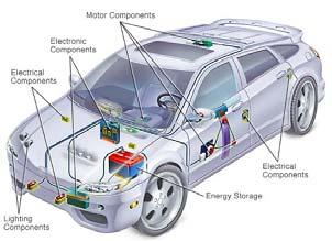

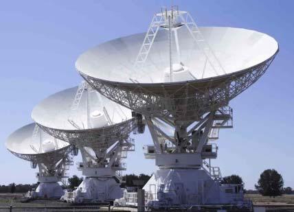
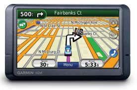
5 What is electronics?

6 Evolution of Electronic Devices
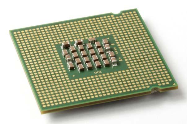
7 Transistors and Moore s Law Transistor: The fundamental building block of modern electronic devices. Moore s Law: the number of transistor that can be placed inexpensively on an integrated circuit die doubles every 18 months.


8 Transistors and Moore s Law Transistor Count Transistor count on an integrated circuit doubles every 18 months. year

9 Minimum Feature Size

10 32 nm technology (2010) Intel s Core i3, i5, i7 processors

11 22/14 nm technology (2011/14) Intel s 3D Tri gate transistor Check this video:
12 About electronics Electronics is everywhere A field at the leading edge of technology, with rapid rate of progress Pushes the limits in speed, degree of integration, automation
13 Where do we start? Materials => Devices => Circuits We already know about passive linear components: resistors, capacitors, inductors We will learn about new nonlinear components: diodes, field effect transistors We will use them to design and build circuits
14 After this course, you ll be able to Calculate conduction properties of materials and simple device structures Explain the operating principles of semiconductor diodes and FETs Determine the in circuit operating state of diodes and FETs Perform large signal analysis of circuits containing diodes and FETs Use a modern schematic capture and computer aided circuit analysis program (SPICE) Calculate the performance parameters for different MOS logic families to design and build circuits
15 EE 331 Devices and Circuits I Chapter 1 Circuit Review
16 Circuit Theory Review Starting point: Ohm s Law (OL) Kirchhoff s voltage law (KVL) Kirchhoff s current law (KCL) Derive: Voltage Division Current Division Thevenin Equivalent Circuits Norton Equivalent Circuits
17 Voltage Division OL: OL: KVL:
18 Current Division OL: OL: KCL:
19 Thevenin Equivalent Circuits Voltage source V Th is the open circuit voltage at the output terminals R Th : equivalent resistance present at the output terminals with all independent sources set to zero
 Open circuit voltage: 7.")
20 Thevenin Equivalent Circuits (e.g. 1) Open circuit voltage: 7.5 V voltage division Set V 1 to zero. 1 kω 2 kω 2 kω 2 kω
21 Thevenin Equivalent Circuits (e.g. 2) KCL: 1 1 KVL: 1 1 1
22 Thevenin Equivalent Circuits (e.g. 2) KVL: ; KCL: /
23 Norton Equivalent Circuits I No : current coming out of the network when terminals are shorted R No : equivalent resistance present at the output terminals with all independent sources set to zero (R No = R Th )

24 Norton Equivalent Circuits (e.g. 1) 5.63 ma Short Circuit current: current division 3.75 ma Set V 1 to zero. 1 kω 2 kω 2 kω 2 kω
25 Norton Equivalent Circuits (e.g. 2) 1 1 / is the same as in Thevenin equivalent circuits
3. Voltage and Current laws
 1 3. Voltage and Current laws 3.1 Node, Branches, and loops A branch represents a single element such as a voltage source or a resistor A node is the point of the connection between two or more elements
3.4 The Single-Loop Circuit Single-loop circuits
 25 3.4 The Single-Loop Circuit Single-loop circuits Elements are connected in series All elements carry the same current We shall determine The current through each element The voltage across each element
Objective of the Lecture
 Objective of the Lecture Present Kirchhoff s Current and Voltage Laws. Chapter 5.6 and Chapter 6.3 Principles of Electric Circuits Chapter4.6 and Chapter 5.5 Electronics Fundamentals or Electric Circuit
ECE321 Electronics I
 ECE321 Electronics Lecture 2: Basic Circuits with Diodes Payman Zarkesh-Ha Office: ECE Bldg. 230B Office hours: Tuesday 2:00-3:00PM or by appointment E-mail: pzarkesh.unm.edu Slide: 1 Review of Last Lecture
Homework Assignment 01
 Homework Assignment 01 In this homework set students review some basic circuit analysis techniques, as well as review how to analyze ideal op-amp circuits. Numerical answers must be supplied using engineering
Announcements. To stop blowing fuses in the lab, note how the breadboards are wired. EECS 42, Spring 2005 Week 3a 1
 Announcements New topics: Mesh (loop) method of circuit analysis Superposition method of circuit analysis Equivalent circuit idea (Thevenin, Norton) Maximum power transfer from a circuit to a load To stop
Lab Experiment No. 4
 Lab Experiment No. Kirchhoff s Laws I. Introduction In this lab exercise, you will learn how to read schematic diagrams of electronic networks, how to draw and use network graphs, how to transform schematics
GENE 123: Electrical Engineering ME 123: Electrical Engineering for Mechanical Engineers
 Department of Electrical and Computer Engineering GENE 123: Electrical Engineering ME 123: Electrical Engineering for Mechanical Engineers TEACHING TEAM: Spring Term 2003 Instructors Name Class Office
The Norwegian University of Science and Technology ENGLISH. EXAM IN TFY 4185 Measurement Technique/Måleteknikk. 1 Dec 2014 Time: 09:00-13:00
 Page 1 of 9 The Norwegian University of Science and Technology ENGLISH Department of Physics Contact person: Name: Patrick Espy Tel: +47 73 55 10 95 (office) or +47 41 38 65 78 (mobile) EXAM IN TFY 4185
DEPARTMENT OF ELECTRONICS AND COMMUNICATION ENGINEERING
 KINGS COLLEGE OF ENGINEERING PUNALKULAM. DEPARTMENT OF ELECTRONICS AND COMMUNICATION ENGINEERING QUESTION BANK SUBJECT CODE : EE1152 SEM / YEAR : II / I SUBJECT NAME : ELECTRIC CIRCUITS AND ELECTRON DEVICES
ECE 201, Section 3 Lecture 12. Prof. Peter Bermel September 17, 2012
 ECE 201, Section 3 Lecture 12 Prof. Peter ermel September 17, 2012 Exam #1: Thursday, Sep. 20 6:307:30 pm Most of you will be in WTHR 200, unless told otherwise Review session tonight at 8 pm (MTH 175)
ECE321 Electronics I
 ECE32 Electronics Lecture 2: Basic Circuits with iodes Payman Zarkesh-Ha Office: ECE Bldg. 230B Office hours: Tuesday 2:00-3:00PM or by appointment E-mail: payman@ece.unm.edu Slide: Review of Last Lecture
University of Portland EE 271 Electrical Circuits Laboratory. Experiment: Kirchhoff's Laws and Voltage and Current Division
 University of Portland EE 271 Electrical Circuits Laboratory Experiment: Kirchhoff's Laws and Voltage and Current Division I. Objective The objective of this experiment is to determine the relationship
12/01/2009. Practice with past exams
 EE40 Final Exam Review Prof. Nathan Cheung 12/01/2009 Practice with past exams http://hkn.eecs.berkeley.edu/exam/list/?examcourse=ee%2040 Slide 1 Overview of Course Circuit components: R, C, L, sources
Fundamentals of Microelectronics
 Fundamentals of Microelectronics CH1 Why Microelectronics? CH2 Basic Physics of Semiconductors CH3 Diode Circuits CH4 Physics of Bipolar Transistors CH5 Bipolar Amplifiers CH6 Physics of MOS Transistors
Thevenin Equivalent Circuits: (Material for exam - 3)
") Thevenin Equivalent Circuits: (Material for exam 3) The Thevenin equivalent circuit is a two terminal output circuit that contains only one source called E TH and one series resistors called R TH. This
Thevenin Equivalent Circuits: (Material for exam 3) The Thevenin equivalent circuit is a two terminal output circuit that contains only one source called E TH and one series resistors called R TH. This
University of Portland EE 271 Electrical Circuits Laboratory. Experiment: Digital-to-Analog Converter
 University of Portland EE 271 Electrical Circuits Laboratory Experiment: Digital-to-Analog Converter I. Objective The objective of this experiment is to build and test a circuit that can convert a binary
Chapter 1. Electronics I - Introduc1on. Electronics vs. Microelectronics. Discrete Circuits vs. Integrated Circuits. Source: B.
 Chapter 1 Electronics I - Introduc1on 1 Electronics vs. Microelectronics Discrete Circuits vs. Integrated Circuits Limit the component count to achieve a small board area Available resistors are in the
Notes. 1. Midterm 1 Thursday February 24 in class.
 Notes 1. Midterm 1 Thursday February 24 in class. Covers through text Sec. 4.3, topics of HW 4. GSIs will review material in discussion sections prior to the exam. No books at the exam, no cell phones,
Electrical and Electronic Principles
 Unit 19: Unit code Electrical and Electronic Principles M/615/1493 Unit level 4 Credit value 15 Introduction Electrical engineering is mainly concerned with the movement of energy and power in electrical
EE 230. Electronic Circuits and Systems. Randy Geiger 2133 Coover
 EE 230 Electronic Circuits and Systems Randy Geiger 2133 Coover rlgeiger@iastate.edu 294-7745 Course Description Linear Systems Frequency domain characterization of electronic circuits and systems transfer
Lecture # 4 Network Analysis
 CPEN 206 Linear Circuits Lecture # 4 Network Analysis Dr. Godfrey A. Mills Email: gmills@ug.edu.gh Phone: 026-907-3163 February 22, 2016 Course TA David S. Tamakloe 1 What is Network Technique o Network
Lecture Week 5. Quiz #2 Ohm s Law Homework Power Review Shorthand Notation Active Components Ideal Op-amps
 Lecture Week 5 Quiz #2 Ohm s Law Homework Power Review Shorthand Notation Active Components Ideal Op-amps Quiz 2 Ohm s Law (20 pts.) Please clear desks and turn off phones and put them in back packs You
COURSE OUTLINE. School of Engineering Technology and Applied Science
 COURSE OUTLINE SCHOOL: School of Engineering Technology and Applied Science DEPARTMENT: Information and Communication Engineering Technology (ICET) PROGRAM: Electronics Engineering Technician & Technology
ESC201A Introducton to Electronics. G Rajshekhar Department of Electrical Engineering IIT Kanpur
 ESC201A Introducton to Electronics G Rajshekhar Department of Electrical Engineering IIT Kanpur Acknowledgements Prof. Baquer Mazhari, EE department Prof. A. R. Harish, EE department Prof. S.S.K. Iyer,
EE 105 Discussion #1: Fundamentals of Circuit Analysis
 EE 105 Discussion #1: Fundamentals of Circuit Analysis 1.1 Ohm s Law V = ir i = V/R 1.2 KCL & KVL Kirchoff s Current Law (KCL) Kirchoff s Voltage Law (KVL) The algebraic sum of all currents entering a
EE105 Fall 2015 Microelectronic Devices and Circuits. Invention of Transistors
 EE105 Fall 2015 Microelectronic Devices and Circuits Prof. Ming C. Wu wu@eecs.berkeley.edu 511 Sutardja Dai Hall (SDH) 1-1 Invention of Transistors - 1947 Bardeen, Shockley, and Brattain at Bell Labs Invented
Source Transformations
 Source Transformations Introduction The circuits in this set of problems consist of independent sources, resistors and a meter. In particular, these circuits do not contain dependent sources. Each of these
Syllabus for: Electronics for F Y B Sc (Electronics) Semester- 1 (With effect from June 2014) PAPER I: Basic Electrical Circuits
 Semester- 1 (With effect from June 2014) PAPER I: Basic Electrical Circuits") Unit I: Passive Devices Syllabus for: Electronics for F Y B Sc (Electronics) Semester- 1 (With effect from June 2014) PAPER I: Basic Electrical Circuits Resistors, Fixed resistors & variable resistors,
Unit I: Passive Devices Syllabus for: Electronics for F Y B Sc (Electronics) Semester- 1 (With effect from June 2014) PAPER I: Basic Electrical Circuits Resistors, Fixed resistors & variable resistors,
Chapter 1. Electronics I - Introduc0on. 1
 Chapter 1 Electronics I - Introduc0on talarico@gonzaga.edu 1 Electronics vs. Microelectronics Discrete Circuits vs. Integrated Circuits Limit the component count to achieve a small board area Available
Unit/Standard Number. LEA Task # Alignment
 1 Secondary Competency Task List 100 SAFETY 101 Demonstrate an understanding of State and School safety regulations. 102 Practice safety techniques for electronics work. 103 Demonstrate an understanding
Circuit Models. Lab 5
 Circuit Models Lab 5 1 Equipment List DC power supply Decade resistance box (2) 1.5kΩ, 2.2kΩ, 560Ω 2 Circuit Models Any circuit can be modeled by either a Thevenin or a Norton model Any circuit whose output
EE 330 Lecture 20. Operating Points for Amplifier Applications Amplification with Transistor Circuits Small Signal Modelling
 EE 330 Lecture 20 Operating Points for Amplifier Applications Amplification with Transistor Circuits Small Signal Modelling Review from Last Lecture Simplified Multi-Region Model Alternate equivalent model
DC/AC CIRCUITS: CONVENTIONAL FLOW TEXTBOOKS
 4 PEARSON CUSTOM ELECTRONICS TECHNOLOGY DC/AC CIRCUITS: CONVENTIONAL FLOW TEXTBOOKS AVAILABLE MARCH 2009 Boylestad Introductory Circuit Analysis, 11/e, 0-13-173044-4 Introduction 32 LC4501 Voltage and
Introduction... 1 Part I: Getting Started with Circuit Analysis Part II: Applying Analytical Methods for Complex Circuits...
 Contents at a Glance Introduction... 1 Part I: Getting Started with Circuit Analysis... 5 Chapter 1: Introducing Circuit Analysis...7 Chapter 2: Clarifying Basic Circuit Concepts and Diagrams...15 Chapter
Electronics for Scientists V and G (Spring 2007)
") Electronics for Scientists V85-0110 and G85-1500 (Spring 2007) Instructor: Prof. Andrew Kent Laboratory Instructor: N/A Prerequisites: Physics II or permission of the instructor Lecture and laboratory,
Electronics for Scientists V85-0110 and G85-1500 (Spring 2007) Instructor: Prof. Andrew Kent Laboratory Instructor: N/A Prerequisites: Physics II or permission of the instructor Lecture and laboratory,
ECE 214 Electrical Circuits Lab Lecture 8
 ECE 214 Electrical Circuits Lab Lecture 8 Vince Weaver http://www.eece.maine.edu/~vweaver vincent.weaver@maine.edu 31 March 2015 Announcements Remember, I am out of town on Tuesday. Lecture will be at
Paper-1 (Circuit Analysis) UNIT-I
 UNIT-I") Paper-1 (Circuit Analysis) UNIT-I AC Fundamentals & Kirchhoff s Current and Voltage Laws 1. Explain how a sinusoidal signal can be generated and give the significance of each term in the equation? 2. Define
Paper-1 (Circuit Analysis) UNIT-I AC Fundamentals & Kirchhoff s Current and Voltage Laws 1. Explain how a sinusoidal signal can be generated and give the significance of each term in the equation? 2. Define
ECE 215 Lecture 8 Date:
 ECE 215 Lecture 8 Date: 28.08.2017 Phase Shifter, AC bridge AC Circuits: Steady State Analysis Phase Shifter the circuit current I leads the applied voltage by some phase angle θ, where 0 < θ < 90 ο depending
Electronic Circuits. Lecturer. Schedule. Electronic Circuits. Books
 Lecturer Electronic Circuits Jón Tómas Guðmundsson Jón Tómas Guðmundsson Office: Room 120, UM-SJTU JI Building Office hours: Monday and Thursday 13:15-14:15 e-mail: tumi@raunvis.hi.is tumi@raunvis.hi.is
UNIVERSITY OF NORTH CAROLINA AT CHARLOTTE Department of Electrical and Computer Engineering
 UNIVERSITY OF NORTH CAROLINA AT CHARLOTTE Department of Electrical and Computer Engineering EXPERIMENT 8 NETWORK ANALYSIS OBJECTIVES The purpose of this experiment is to mathematically analyze a circuit
Homework Assignment 01
 Homework Assignment 01 In this homework set students review some basic circuit analysis techniques, as well as review how to analyze ideal op-amp circuits. Numerical answers must be supplied using engineering
Digital Electronics Part II - Circuits
 Digital Electronics Part II - Circuits Dr. I. J. Wassell Gates from Transistors 1 Introduction Logic circuits are non-linear, consequently we will introduce a graphical technique for analysing such circuits
Leading at the edge TECHNOLOGY AND MANUFACTURING DAY
 Leading at the edge 22FFL technology MARK BOHR Intel Senior Fellow, Technology and Manufacturing Group Director, Process Architecture and Integration Disclosures Intel Technology and Manufacturing Day
Prelab 4 Millman s and Reciprocity Theorems
 Prelab 4 Millman s and Reciprocity Theorems I. For the circuit in figure (4-7a) and figure (4-7b) : a) Calculate : - The voltage across the terminals A- B with the 1kΩ resistor connected. - The current
EE Analog and Non-linear Integrated Circuit Design
 University of Southern California Viterbi School of Engineering Ming Hsieh Department of Electrical Engineering EE 479 - Analog and Non-linear Integrated Circuit Design Instructor: Ali Zadeh Email: prof.zadeh@yahoo.com
hing/fall16/electric_circuits.html
 http://sist.shanghaitech.edu.cn/faculty/zhoupq/teac hing/fall16/electric_circuits.html Circuit Terminology & Kirchhoff s Laws 9/14/2016 Reading: Chapter 1&2&3 2 Outline Circuit Terminology Charge, Current,
DEGREE: BACHELOR IN INDUSTRIAL ELECTRONICS AND AUTOMATION YEAR: 2ND TERM: 2ND
 SESSION WEEK COURSE: ELECTRONICS ENGINEERING FUNDAMENTALS DEGREE: BACHELOR IN INDUSTRIAL ELECTRONICS AND AUTOMATION YEAR: 2ND TERM: 2ND The course has 29 sessions distributed during 15 weeks. The duration
Homework Assignment 01
 Homework Assignment 01 In this homework set students review some basic circuit analysis techniques, as well as review how to analyze ideal op-amp circuits. Numerical answers must be supplied using engineering
Academic Course Description. BHARATH University Faculty of Engineering and Technology Department of Electrical and Electronics Engineering
 BEE101- Basic Electrical and Electronics Engineering Academic Course Description BHARATH University Faculty of Engineering and Technology Department of Electrical and Electronics Engineering BEE101 Basic
EE 330 Laboratory 8 Discrete Semiconductor Amplifiers
 EE 330 Laboratory 8 Discrete Semiconductor Amplifiers Fall 2017 Contents Objective:... 2 Discussion:... 2 Components Needed:... 2 Part 1 Voltage Controlled Amplifier... 2 Part 2 Common Source Amplifier...
De Anza College Department of Engineering Engr 37-Intorduction to Circuit Analysis
 De Anza College Department of Engineering Engr 37-Intorduction to Circuit Analysis Spring 2017 Lec: Mon to Thurs 8:15 am 9:20 am S48 Office Hours: Thursday7:15 am to 8:15 am S48 Manizheh Zand email: zandmanizheh@fhda.edu
LINEAR CIRCUIT ANALYSIS (EED) U.E.T. TAXILA 07 ENGR. M. MANSOOR ASHRAF
 U.E.T. TAXILA 07 ENGR. M. MANSOOR ASHRAF") LINEAR CIRCUIT ANALYSIS (EED) U.E.T. TAXILA 07 ENGR. M. MANSOOR ASHRAF INTRODUCTION Applying Kirchhoff s laws to purely resistive circuits results in algebraic equations. While applying laws to RC and
LINEAR CIRCUIT ANALYSIS (EED) U.E.T. TAXILA 07 ENGR. M. MANSOOR ASHRAF INTRODUCTION Applying Kirchhoff s laws to purely resistive circuits results in algebraic equations. While applying laws to RC and
Scheme & Syllabus. B.Sc. Electronics. Honours Course. I st & II nd Semester. w.e.f. July Devi Ahilya Vishwavidyalaya, Indore (M.P.
 Scheme & Syllabus of B.Sc. Electronics Honours Course I st & II nd Semester w.e.f. July 2011 Devi Ahilya Vishwavidyalaya, Indore (M.P.), 452001 SEMESTER SYSTEM, 2011-2014 PROPOSED SCHEME FOR B.Sc. ELECTRONICS
Experiment 10 Current Sources and Voltage Sources
 Experiment 10 Current Sources and Voltage Sources W.T. Yeung and R.T. Howe UC Berkeley EE 105 Fall 2003 1.0 Objective This experiment will introduce techniques for current source biasing. Several different
Designing Information Devices and Systems II Fall 2017 Note 1
 EECS 16B Designing Information Devices and Systems II Fall 2017 Note 1 1 Digital Information Processing Electrical circuits manipulate voltages (V ) and currents (I) in order to: 1. Process information
55:041 Electronic Circuits The University of Iowa Fall Exam 1 Solution
 Exam 1 Name: Score /60 Question 1 Short takes. For True/False questions, write T, or F in the right-hand column as appropriate. For other questions, provide answers in the space provided. 1. Tue of false:
Entry Level Assessment Blueprint Electronics Technology
 Blueprint Test Code: 4135 / Version: 01 Specific Competencies and Skills Tested in this Assessment: Safety Practices Demonstrate safe working procedures Explain the purpose of OSHA and how it promotes
EQUIVALENT EQUIPMENT CIRCUITS
 INTRODUCTION EQUIVALENT EQUIPMENT CIRCUITS The student will analyze the internal properties of the equipment used in lab. The input resistance of the oscilloscope and digital multimeter when used as a
3.1 ignored. (a) (b) (c)
 (b) (c)") Problems 57 [2] [3] [4] S. Modeling, Analysis, and Design of Switching Converters, Ph.D. thesis, California Institute of Technology, November 1976. G. WESTER and R. D. MIDDLEBROOK, Low-Frequency Characterization
Problems 57 [2] [3] [4] S. Modeling, Analysis, and Design of Switching Converters, Ph.D. thesis, California Institute of Technology, November 1976. G. WESTER and R. D. MIDDLEBROOK, Low-Frequency Characterization
EE42: Running Checklist of Electronics Terms Dick White
 EE42: Running Checklist of Electronics Terms 14.02.05 Dick White Terms are listed roughly in order of their introduction. Most definitions can be found in your text. Terms2 TERM Charge, current, voltage,
Electronics 101 v2.0
 Electronics 101 v2.0 Jean-François Duval (jfduval@mit.edu) & Palash Nandy (palash@media.mit.edu) MIT MAS863: How To Make (almost) Anything, 10/15/2015 Recitation Plan Introduction & goal Essential Laws
Page 1. Date 15/02/2013
 Page 1 Date 15/02/2013 Final Term Examination Fall 2012 Phy301-Circuit Theory 1. State kirchhoff s current law (KCL) Marks: 2: Answer: (PAGE 42) KIRCHHOF S CURRENT LAW Sum of all the currents entering
ELECTRONICS WITH DISCRETE COMPONENTS
 ELECTRONICS WITH DISCRETE COMPONENTS Enrique J. Galvez Department of Physics and Astronomy Colgate University WILEY John Wiley & Sons, Inc. ^ CONTENTS Preface vii 1 The Basics 1 1.1 Foreword: Welcome to
Welcome to your second Electronics Laboratory Session. In this session you will learn about how to use resistors, capacitors and inductors to make
 Welcome to your second Electronics Laboratory Session. In this session you will learn about how to use resistors, capacitors and inductors to make simple circuits. You will find out how these circuits
EE 501 Lab 10 Output Amplifier Due: December 10th, 2015
 EE 501 Lab 10 Output Amplifier Due: December 10th, 2015 Objective: Get familiar with output amplifier. Design an output amplifier driving small resistor load. Design an output amplifier driving large capacitive
Unit 2. Circuit Analysis Techniques. 2.1 The Node-Voltage Method
 Unit 2 Circuit Analysis Techniques In this unit we apply our knowledge of KVL, KCL and Ohm s Law to develop further techniques for circuit analysis. The material is based on Chapter 4 of the text and that
CRN: MET-487 Instrumentation and Automatic Control June 28, 2010 August 5, 2010 Professor Paul Lin
 CRN: 32030 MET-487 Instrumentation and Automatic Control June 28, 2010 August 5, 2010 Professor Paul Lin Course Description: Class 2, Lab 2, Cr. 3, Junior class standing and 216 Instrumentation for pressure,
Veer Narmad South Gujarat University, Surat
 Unit I: Passive circuit elements (With effect from June 2017) Syllabus for: F Y B Sc (Electronics) Semester- 1 PAPER I: Basic Electrical Circuits Resistors, resistor types, power ratings, resistor colour
UNIT I Introduction to DC & AC circuits
 SIDDHARTH GROUP OF INSTITUTIONS :: PUTTUR Siddharth Nagar, Narayanavanam Road 517583 QUESTION BANK (DESCRIPTIVE) Subject with Code: Basic Electrical and Electronics Engineering (16EE207) Year & Sem: II-B.
vi. Apply 3V DC to your circuit network and measure the current through each resistor vii. Verify Kirchhoff s Current Law
 Lab Experiment No. EE1106, Fall 201 Connections I. Introduction In this lab exercise, you will learn how to read schematic diagrams of electronic networks, how to transform schematics into actual element
Lab 2: Common Emitter Design: Part 2
 Lab 2: Common Emitter Design: Part 2 ELE 344 University of Rhode Island, Kingston, RI 02881-0805, U.S.A. 1 Linearity in High Gain Amplifiers The common emitter amplifier, shown in figure 1, will provide
Electronic Devices, 9th edition Thomas L. Floyd. Input signal. R 1 and R 2 are selected to establish V B. If the V CE
 3/9/011 lectronic Devices Ninth dition Floyd hapter 5: Transistor ias ircuits The D Operating Point ias establishes the operating point (Q-point) of a transistor amplifier; the ac signal (ma) moves above
Analysis and Design of Analog Integrated Circuits Lecture 1. Overview of Course, NGspice Demo, Review of Thevenin/Norton Modeling
 Analysis and Design of Analog Integrated Circuits Lecture 1 Overview of Course, NGspice Demo, Review of Thevenin/Norton Modeling Michael H. Perrott January 22, 2012 Copyright 2012 by Michael H. Perrott
CHAPTER 9. Sinusoidal Steady-State Analysis
 CHAPTER 9 Sinusoidal Steady-State Analysis 9.1 The Sinusoidal Source A sinusoidal voltage source (independent or dependent) produces a voltage that varies sinusoidally with time. A sinusoidal current source
Lecture Week 8. Quiz #5 KCL/KVL Homework P15 Capacitors RC Circuits and Phasor Analysis RC filters Bode Plots Cutoff frequency Homework
 Lecture Week 8 Quiz #5 KCL/KVL Homework P15 Capacitors RC Circuits and Phasor Analysis RC filters Bode Plots Cutoff frequency Homework Quiz 5 KCL/KVL (20 pts.) Please clear desks and turn off phones and
Survival Skills for Circuit Analysis
 P. R. Nelson Fall 2010 WhatToKnow - p. 1/46 Survival Skills for Circuit Analysis What you need to know from ECE 109 Phyllis R. Nelson prnelson@csupomona.edu Professor, Department of Electrical and Computer
EE 330 Laboratory 8 Discrete Semiconductor Amplifiers
 EE 330 Laboratory 8 Discrete Semiconductor Amplifiers Fall 2018 Contents Objective:...2 Discussion:...2 Components Needed:...2 Part 1 Voltage Controlled Amplifier...2 Part 2 A Nonlinear Application...3
Homework Assignment 02
 Question 1 (2 points each unless noted otherwise) 1. Is the following circuit an STC circuit? Homework Assignment 02 (a) Yes (b) No (c) Need additional information Answer: There is one reactive element
ECE 255, MOSFET Basic Configurations
 ECE 255, MOSFET Basic Configurations 8 March 2018 In this lecture, we will go back to Section 7.3, and the basic configurations of MOSFET amplifiers will be studied similar to that of BJT. Previously,
EMT 251 Introduction to IC Design
 EMT 251 Introduction to IC Design (Pengantar Rekabentuk Litar Terkamir) Semester II 2011/2012 Introduction to IC design and Transistor Fundamental Some Keywords! Very-large-scale-integration (VLSI) is
Exam Below are two schematics of current sources implemented with MOSFETs. Which current source has the best compliance voltage?
 Exam 2 Name: Score /90 Question 1 Short Takes 1 point each unless noted otherwise. 1. Below are two schematics of current sources implemented with MOSFETs. Which current source has the best compliance
Electronics Circuits and Devices I with Lab
 ECET110 Electronics Circuits and Devices I with Lab Term Information: 2009 Spring Credit Hours 4 Contact Hours: 5 Instructor Information: Name: Pui-chor Wong Telephone contact numbers: 403-207-3108 Office
SIDDHARTH GROUP OF INSTITUTIONS :: PUTTUR Siddharth Nagar, Narayanavanam Road QUESTION BANK (DESCRIPTIVE) PART - A
 PART - A") SIDDHARTH GROUP OF INSTITUTIONS :: PUTTUR Siddharth Nagar, Narayanavanam Road 517583 QUESTION BANK (DESCRIPTIVE) Subject with Code: Basic Electrical and Electronics Engineering (16EE207) Year & Sem: II-B.
SIDDHARTH GROUP OF INSTITUTIONS :: PUTTUR Siddharth Nagar, Narayanavanam Road 517583 QUESTION BANK (DESCRIPTIVE) Subject with Code: Basic Electrical and Electronics Engineering (16EE207) Year & Sem: II-B.
EE1305/EE1105 Homework Problems Packet
 EE1305/EE1105 Homework Problems Packet P1 - The gate length of a tri-gate transistor is 22 nm. How many gate lengths fit across a human hair with a diameter of 100 μm? Show all units and unit conversions
In 1951 William Shockley developed the world first junction transistor. One year later Geoffrey W. A. Dummer published the concept of the integrated
 Objectives History and road map of integrated circuits Application specific integrated circuits Design flow and tasks Electric design automation tools ASIC project MSDAP In 1951 William Shockley developed
Series Circuits. Chapter
 Chapter 4 Series Circuits Topics Covered in Chapter 4 4-1: Why I Is the Same in All Parts of a Series Circuit 4-2: Total R Equals the Sum of All Series Resistances 4-3: Series IR Voltage Drops 4-4: Kirchhoff
Lab 4. Transistor as an amplifier, part 2
 Lab 4 Transistor as an amplifier, part 2 INTRODUCTION We continue the bi-polar transistor experiments begun in the preceding experiment. In the common emitter amplifier experiment, you will learn techniques
Exercise 1: Thevenin to Norton Conversion
 Exercise 1: Thevenin to Norton Conversion EXERCISE OBJECTIVE When you have completed this exercise, you will be able to convert a voltage source to a current source. You will verify your results by comparing
Lecture 1. EE 215 Electronic Devices & Circuits. Semiconductor Devices: Diodes. The Ideal Diode
 Lecture 1 EE 215 Electronic Deices & Circuits Asst Prof Muhammad Anis Chaudhary EE 215 Electronic Deices & Circuits Credit Hours: 3 1 Course Book: Adel S. Sedra and Kenneth C. Smith, Microelectronic Circuits,
EE 434 Lecture 2. Basic Concepts
 EE 434 Lecture 2 Basic Concepts Review from Last Time Semiconductor Industry is One of the Largest Sectors in the World Economy and Growing All Initiatives Driven by Economic Opportunities and Limitations
Charge Current Voltage
 ECE110 Introduction to Electronics What is? Charge Current Voltage 1 Kirchhoff s Current Law Current in = Current out Conservation of charge! (What goes in must come out, or the total coming in is zero)
Electronics - PHYS 2371/2
 TODAY Quick Review-Basics Alternating Current, Ch-7 - RMS - problem 7-1 Elements of AC Circuits, Ch-8 - resistor, capacitor, inductors(l) - impedance (Z), reactance (X) (video break) Step Function Analysis,
PART-A UNIT I Introduction to DC & AC circuits
 SIDDHARTH GROUP OF INSTITUTIONS :: PUTTUR (AUTONOMOUS) Siddharth Nagar, Narayanavanam Road 517583 QUESTION BANK (DESCRIPTIVE) Subject with Code : Basic Electrical and Electronics Engineering (16EE207)
Introductory Electronics for Scientists and Engineers
 Introductory Electronics for Scientists and Engineers Second Edition ROBERT E. SIMPSON University of New Hampshire Allyn and Bacon, Inc. Boston London Sydney Toronto Contents Preface xiü 1 Direct Current
MEASUREMENT AND INSTRUMENTATION STUDY NOTES UNIT-I
 MEASUREMENT AND INSTRUMENTATION STUDY NOTES The MOSFET The MOSFET Metal Oxide FET UNIT-I As well as the Junction Field Effect Transistor (JFET), there is another type of Field Effect Transistor available
Electrical, Electronic and Communications Engineering Technology/Technician CIP Task Grid
 Secondary Task List 100 SAFETY 101 Describe OSHA safety regulations. 102 Identify, select, and demonstrate proper hand tool use for electronics work. 103 Recognize the types and usages of fire extinguishers.
UNIVERSITY OF NAIROBI COLLEGE OF BIOLOGICAL AND PHYSICAL SCIENCES FACULTY OF SCIENCE SPH 307 INTRODUCTORY ELECTRONICS
 UNIVERSITY OF NAIROBI COLLEGE OF BIOLOGICAL AND PHYSICAL SCIENCES FACULTY OF SCIENCE SPH 307 INTRODUCTORY ELECTRONICS Dr. Kenneth A. Kaduki Department of Physics University of Nairobi Reviewer: Prof. Bernard
Osmania University B.Sc Electronics - Syllabus (under CBCS w.e.f ) I ST and II nd Year
 I ST and II nd Year") Osmania University B.Sc Electronics - Syllabus (under CBCS w.e.f 2016-2017) I ST and II nd Year UNIT - I B.Sc. ELECTRONICS SYLLABUS B.Sc. I YEAR Semester - I DSC- Paper I : Circuit Analysis Total number
Osmania University B.Sc Electronics - Syllabus (under CBCS w.e.f 2016-2017) I ST and II nd Year UNIT - I B.Sc. ELECTRONICS SYLLABUS B.Sc. I YEAR Semester - I DSC- Paper I : Circuit Analysis Total number