FM Cl. DEPARTMENT OF THE ARMY No. 1 WASHINGTON, D.C., 31 December 1968 TOPOGRAPHIC SYMBOLS. FM 21-31, 19 June 1961, is changed as follows:
|
|
|
- Oliver Rodgers
- 6 years ago
- Views:
Transcription
1 *FM Items below added to Chapter 2 by Change 1 Joint Operations Graphics Elevations Vegetation Roads In Foreign Areas Populated Places And Landmark Features Boundaries Aerodromes Radio Navigation And Communications Facilities Controlled Airspace Magnetic Variation Data Visual Aids And Obstructions Pictomaps 1
2 CHANGE FM Cl HEADQUARTERS DEPARTMENT OF THE ARMY No. 1 WASHINGTON, D.C., 31 December 1968 TOPOGRAPHIC SYMBOLS FM 21-31, 19 June 1961, is changed as follows:
3 2
4 3
5 4
6 5
7 6
8 7
9 Page 86. Paragraphs 23.1 and 23.2 and figures 243 through 332 are added as follows: Joint Operations Graphics a. Purpose and Scope. Joint Operations Graphics are produced in both ground and air versions. The ground version is designated as Series 1501; the air version is designated as Series 1501 AIR. Both versions are designed to provide common base graphics for use in combined operations by the ground and air forces of allied nations. The topographic information is identical on both the ground and air versions. b. Unit of Vertical Measure. On the ground version, elevation and contour values are shown in meters. These values are converted to foot units on the air version. c. Aeronautical Information. Both versions contain identical information regarding aerodromes and obstructions to pilotage. The air version contains additional information concerning aids to air navigation. d. Shaded Relief. Both versions contain an identical representation of shading, to provide a rapid recognition of slope and landforms. The shading also serves as a means of correlating contours and elevations, with emphasis on the more significant terrain features. e. Elevation Tints. Both versions contain a representative system of color tints which depict areas of the same elevation range. A key box on each version indicates the elevation ranges and their corresponding color tints. j. Symbols. The following approved symbols for Joint Operations Graphics are in addition to, or different from, the standard medium-scale symbols shown in figures 1 through 242: Note: The remaining pages from Change 1 have been moved into the body of Chapter 2 of this manual begining at page 86. 8
10 By Order of the Secretary of the Army: Official: KENNETH G. WICKHAM, Major General, United States Army, The Adjutant General. W. C. WESTMORELAND, General, United States Army, Chief of Staff. Distribution: To be distributed in accordance with DA Form requirements for Map Reading. 45
11 CHAPTER 1 INTRODUCTION 1. Purpose This manual describes the topographic symbols and abbreviations authorized for use by all echelons in the interpretation of military maps, overlays, and related features and activities. 2. Scope This manual is divided into four chapters. a. Chapter 1 contains general information on the use of topographic symbols, gives the basic scales for topographic maps, defines topographic maps, and discusses map detail, map accuracy, and map colors. b. Chapter 2 gives examples and illustrations of topographic symbols arranged by categories, such as d r a i n a g e features, relief features, and roads. c. Chapter 3 gives topographic abbreviations, their scope and application. d. Chapter 4 discusses marginal information. 3. References Appendix I is a list of publications which give detailed information on maps and mapping, foreign conventional signs and symbols, reference data for the various services, transportation and signal facilities, and abbreviations for administrative and electrically transmitted messages. 4. Symbols and Abbreviations a. Some of the symbols appearing on published maps may not agree entirely with those shown in this manual, since it is necessary to devise or modify symbols to portray conditions or features which are unique to the area being mapped. Consequently, before any map is used, the symbol legend appearing in the margin should be carefully studied. 2 b. The symbols and abbreviations given in this manual are the result of standardization proceedings and are in general agreement with those employed by the British Army, the Canadian Army, the Aeronautical Chart and Information Service of the U.S. Air Force, the Hydrographic Office of the U.S. Navy, the U.S. Coast and Geodetic Survey, the U.S. Forest Service, the U.S. Geological Survey, and the Tennessee Valley Authority. C. Department of the Army units engaged in map making will be guided by AR 117-5, by TM so far as the symbols given as examples do not conflict with those given here, and by the specifications contained in technical publications prepared under the direction of the Chief of Engineers. d. Abbreviations given in this manual are for topographic use only and in some instances conflict with those given in AR , which are authorized for use in military records, publications, correspondence, messages, and in field work. In accordance with AR , abbreviations will not be used if uncertainty may result. e. The information contained herein is applicable without modification to both nuclear and nonnuclear warfare. 5. Use of Special Symbols Where no symbol is prescribed for a specialized local feature, the map maker is authorized to use a special symbol, providing a. There is no conflict with symbols shown in this manual. b. Any special symbol used is explained either in the legend of the map or by appropriate labeling within the body of the map, so that no uncertainty may result.
12 6. Scales of Topographic Maps a. Maps fall into the following general scale categories: Small scale :600,000 and smaller. Medium scale..... Larger than 1:600,000 but smaller than 1:75,000. Large scale :75,000 and larger. b. Standard scales for Department of the Army topographic maps are 1:1,000,000, 1:250,- 000, 1:100,000, 1:50,000, and 1:25,000. Military city maps normally are published at the scale of 1:12,500. Photomaps normally are published at 1:25,000. General maps at scales smaller than 1:1,000,000 are issued for special purposes. c. Depending upon the availability of mapping information and the importance of the area, the scale of 1:500,000 is sometimes substituted for 1:250,000. d. All of the above types and scales of maps will not necessarily be available for a particular area. Their issue will be governed by military and logistic considerations. e. Maps with scales different from those given above occasionally will be encountered. Usually, they are foreign military maps. The most common examples are 1:62,500 or 1 :63,- 360 in place of 1 :50,000; 1:125,000 in place of 1 :100,000; and 1:253,440 in place of 1:250,000, In the United States, nonmilitary governmental mapping agencies may use other scales such as 1:24,000 or 1:31,680 in place of 1 :25,000; and 1:48,000 or 1:62,500 in place of 1:50, Topographic Maps a. Introduction. A topographic map is a graphic representation to scale, horizontal and vertical, of some portion of the earth s surface, systematically plotted on a plane surface. The ideal situation would be realized if every feature on the portion of the earth being mapped could be shown in its true shape, orientation, and proportion. Unfortunately, such a representation is impossible. This is evident when one considers that on a map at the scale of 1:50,000, a square mile must be condensed into a small square approximately 1.27 by 1.27 inches. If every feature were plotted true to scale, the resulting map would be impossible to read, for many items would be drawn so minutely as to be unrecognizable even with a magnifying glass. For a map to be intelligible, features must be indicated by symbols. Many of these must necessarily be exaggerated in size for legibility. For example, on a map at the scale of 1:50,000 the prescribed symbol for a small house covers an area corresponding to about 85 feet square, the scaled width of a road measures about 95 feet; the symbol for a singletrack railroad occupies a width equivalent to about 165 feet on the ground. Consequently, only the landmarks and important features of an area can be shown. Those shown on a map represent the characteristic pattern of the area and are usually those most readily recognized in the field. b. Map Detail. Map detail represents ground features as they existed at the date of map compilation or latest revision. Since man is continually building, demolishing, and changing ground features, the detail appearing on a map may not exactly match that appearing on the ground. This is especially true in developed areas. The amount of detail shown on a map increases with its scale. A map attempts to show the maximum of detail without impairing legibility. In areas of heavy cultural density, many of the less important items must be omitted. In areas of sparse density, fewer items are omitted. When deletions are necessary because of the density of detail, care is taken to retain the general pattern of the features in the area. For example, where all buildings of a group cannot be shown, those retained portray the general pattern of the group without exaggerating the area covered. Similarly, where numerous ditches, streams, levees, and the like exist, the less important are omitted and the more important are retained to show the characteristic pattern of the features in the area. c. Symbols. So far as is practicable, a mapped feature is shown by the same symbol on maps of different scales, but certain modifications and departures are necessary because of varying map uses and scales. Normally, symbols resemble the features they represent. The center and the orientation of a symbol usually correspond to the true center and orientation of the feature represented. All line features such as roads, railroads, streams, power lines, and similar features retain, within 3
13 the limitations of scale, the variations of alinement which actually exist. Along such features as roads, the locations of buildings and other features are necessarily displaced because of the exaggerated size of the symbols. Reference to the positions of such features must be made with caution. d. Accuracy of Maps. On a map of 1:1,000,- 000, a sixteenth of an inch represents approximately 1 mile; on a map of 1:250,000, a quarter of an inch represents approximately 1 mile. It is apparent, then, that on such maps it is impossible to obtain the precise accuracy in plotting possible on large-scale maps. Smalland medium-scale maps normally are compiled from the best available larger-scale maps. Since these sources vary in reliability, the map user should study the coverage diagram shown in the margin of the map to determine the general reliability of the map. On most large-scale maps of areas within the continental limits of the United States, 90 percent of all features shown are within 1/50 inch of their true geographic positions. The remaining 10 percent are within 1/20 inch. Ninety percent of the contours are accurate within one-half of the basic contour interval, and 90 percent of the spot heights (elevations of particular locations) are accurate within one-fourth of the contour interval. In compiling large-scale maps covering foreign areas, it is not always possible to achieve the high standards of accuracy obtainable on maps of the United States. The accuracy standards of such maps usually may be determined from the marginal coverage diagram. e. Map Colors. Topographic symbols usually appear in characteristic colors: black for cultural (man-made) features other than roads, blue for water features, brown or gray for relief features, green for vegetation, and red for road classifications. Modifications of these colors occasionally are used to portray unique circumstances. Consequently, the symbol legend and other marginal information should be carefully studied before using any map. 4
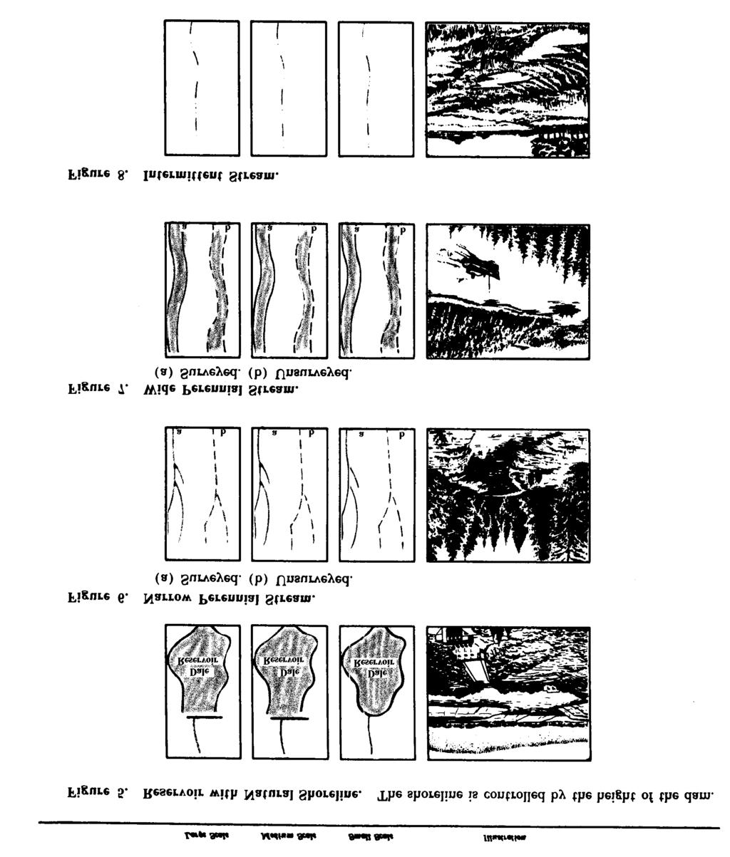
14 CHAPTER 2 TOPOGRAPHIC SYMBOLS 8. Scope This chapter illustrates and explains the topographic symbols used on military maps of all scales. The symbols are in general the same for all categories, but because of differences in use and scales, certain symbols are modified or omitted on medium- and small-scale maps. 9. Drainage Features a. A perennial feature contains water during most of the year. b. An intermittent feature contains water during only part of the year. The shoreline of an intermittent lake or pond is represented as indefinite and approximate. c. A dry or cyclical feature or a wash is usually dry. The limits of such features are represented as indefinite. d. Symbols. The following pages contain the approved symbols for drainage features: 5
15 6
16 7
17 8
18 9
19 10
20 . 11
21 12
22 13
23 14
24 15
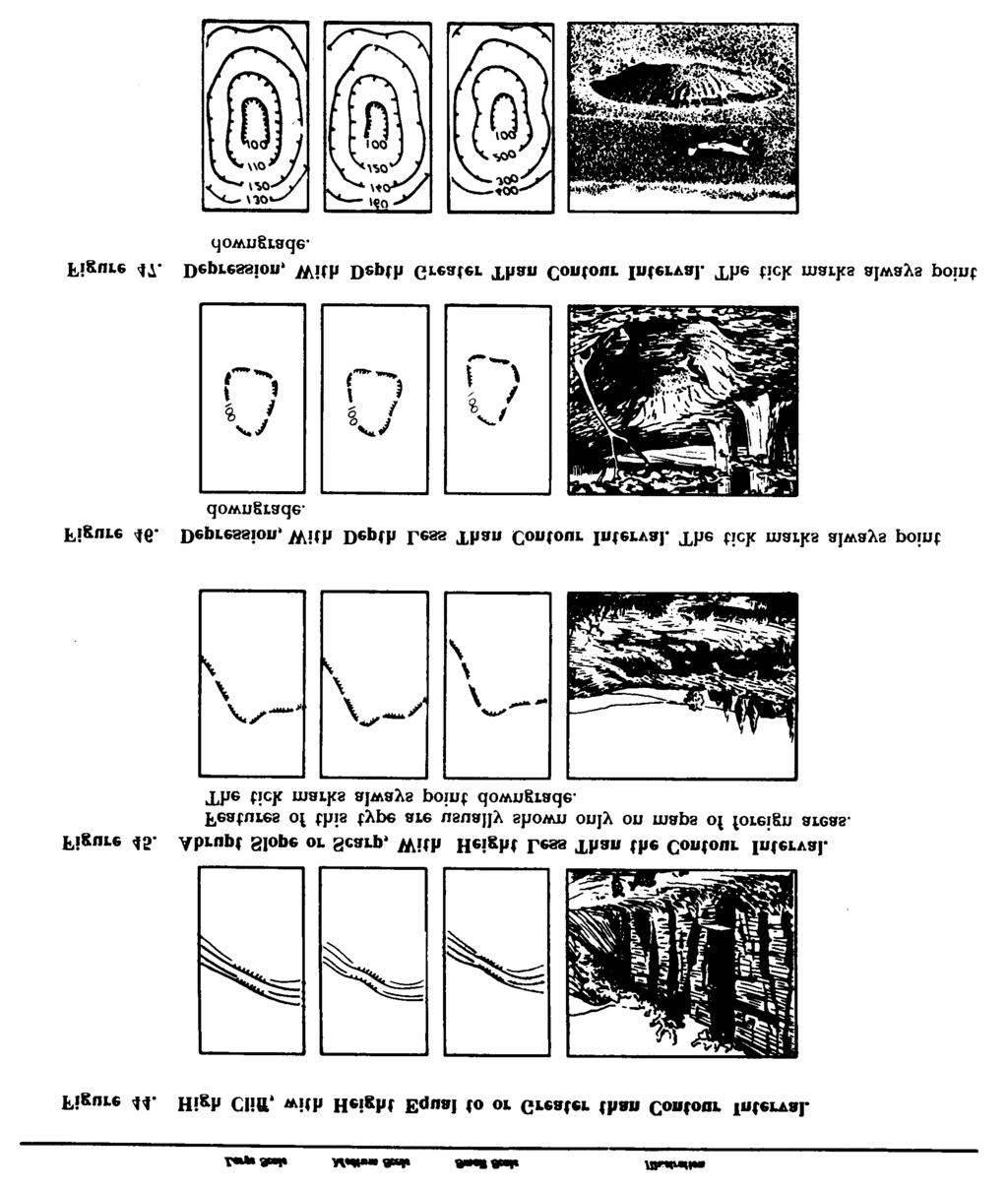
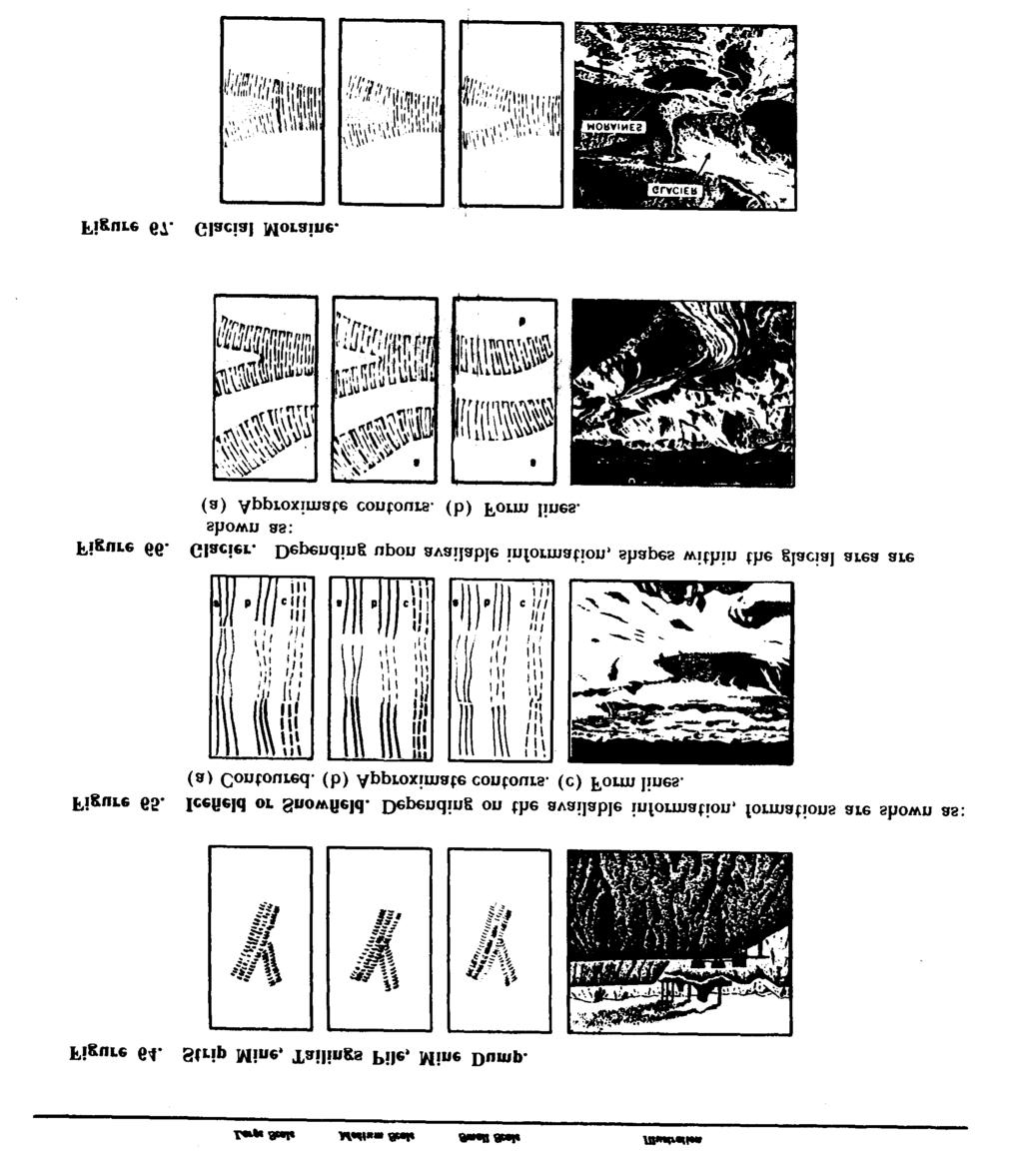
25 Relief Features a. Methods of Showing Relief. Depending upon the accuracy of information, the shapes of the terrain are shown on a map by lines representing contours, approximate contours, and form lines. Any one or all of these methods may be used on a single map. On medium- and small-scale maps, significant relief features may be shown by hachures when available data are insufficient to warrant the use of contours. On large- and medium-scale maps, the lines usually are printed in brown. Also, on mediumscale maps, hill shading usually is added over the brown lines, to print gray. This creates a three-dimensional effect and permits a ready appreciation of the terrain, since the hills and ridges stand out much as they would on a relief map. On small-scale maps the contour lines usually are printed in gray. Normally, on small-scale maps, the contours are supplemented by layer tints. A key box on each map indicates the elevation bands and their corresponding tints. b. Units of Measure. Except in the United States and a few other countries where the foot is the standard unit of measure, the elevations on military maps are in terms of the meter (39.37 inches or 3.28 feet). c. Contours. Relief normally is shown by contour lines. A contour line on a map represents an imaginary line on the earth s surface, all points of which, within permissible tolerances, are of the same elevation above a fixed datum, usually mean sea level. To aid the map user, every fifth contour is a heavier line. These are commonly referred to as index contours. The remaining contours are called intermediate contours. In certain areas on a map, the normal contour interval is sometimes too large to present significant topographic formations correctly and supplementary half-interval contours are added. On small-scale maps, index contours are shown by using layer tints. d. Approximate Contours. Whenever there is any question as to the reliability of the source material or of the survey, approximate contours are substituted for normal contours. An approximate contour on a map represents an imaginary line on the earth s surface, all points of which are estimated to be of the same elevation. As with normal contours, a distinction is made between index, intermediate, and supplementary contours. e. Contour Intervals. Contour lines are drawn on a map at definite elevation intervals. Using a given contour interval, the lines are far apart in flat areas and close together in hilly areas. Consequently, to present the best picture, the size of the contour interval used varies with the nature of the terrain, although normally a contour interval is constant in a series of map sheets. On sheets where the relief is generally flat or gently rolling, a smaller contour interval is used than on sheets where the relief is generally hilly. Scale also affects the contour interval; if the contour interval on a 1:25,000 scale map were 5 meters, for example, the interval used on a 1:50,000 map covering the same area would be 10 meters. f. Form Lines. When available information is insufficient to warrant the use of either normal or approximate contours, form lines are used. Normally, form lines are used only in areas outside the United States. Form lines collectively portray the general shapes of topographic features, but with little or no reference to a datum plane. They do not present an accurate representation of the terrain, but merely illustrate the general topographic shapes of an area. Since the lines are based on little or no control, their intervals cannot be used to estimate differences in elevations. g. Hachures. Hachures are used on mediumand small-scale maps to indicate promontories, where available data are insufficient to warrant the use of normal or approximate contours, but are sufficient to determine the location of the promontories. Hachures also are used in conjunction with normal or approximate, contours to indicate important promontories which would not be properly depicted otherwise, because of the contour interval and the nature of the terrain. h. Marginal Notes. Before reading relief from the map, the user should determine the contour interval and the nature of any other methods used to show relief. This information is found in the margin of the map either in the contour interval note or the layer tint box. Other special notes pertaining to relief are sometimes found in the lower margin. The user should also study the coverage diagram or re-

26 liability diagram in the margin to obtain additional evaluation of contour accuracy. i. Symbols. The following pages contain the approved symbols for relief features. 17
27 18
28 19
29 20
30 21
31 22
32 23
33 24
34 25
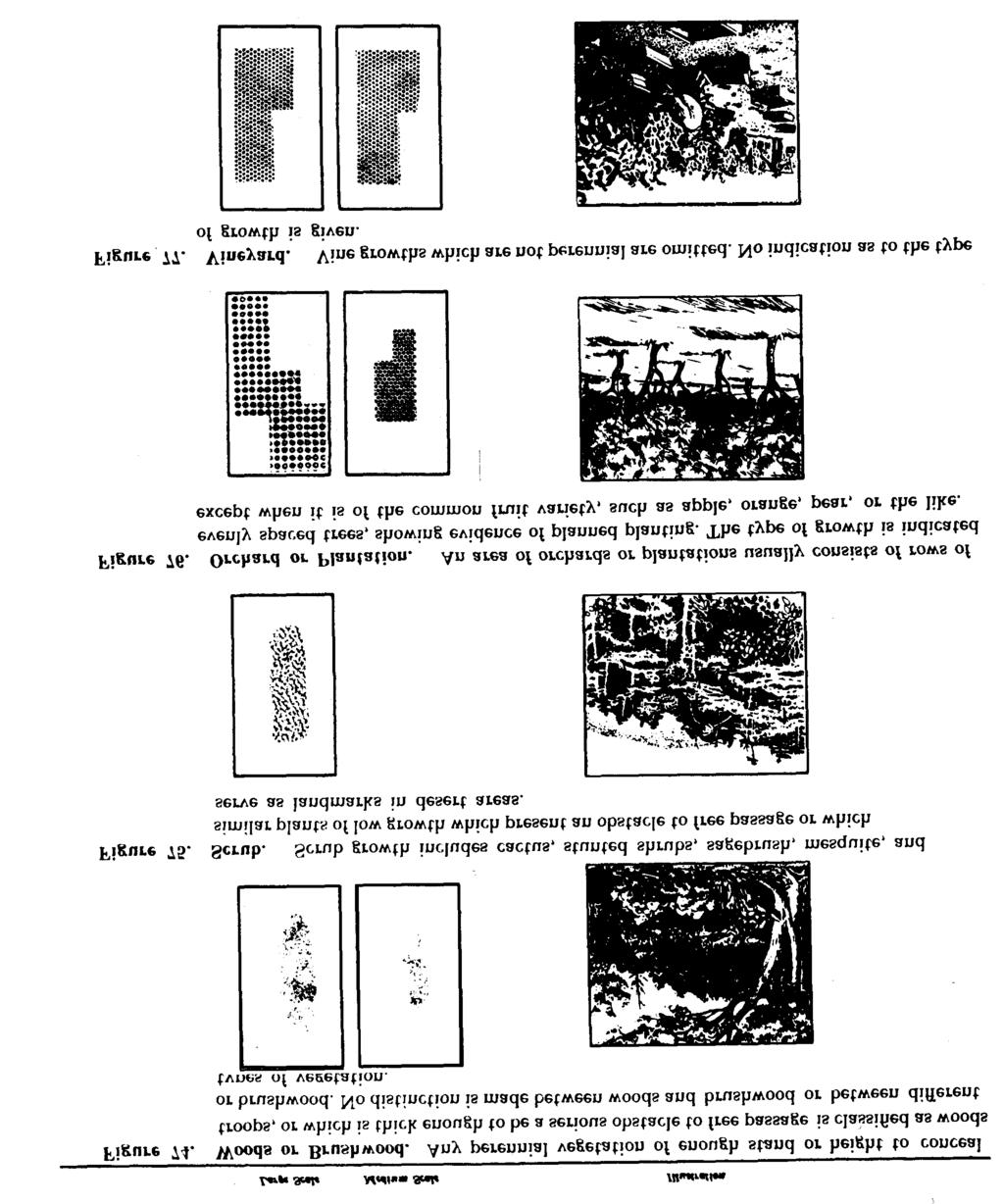
35 11. Vegetation Features a. General. Although special care is taken in mapping woodland cover, vegetation in many areas is subject to rapid growth or to elimination by cutting or burning. Before using the map, the user should determine the last date of information of the map (found in the notes in the lower left margin) and gage the reliability of the woodland information accordingly. The symbols used indicate such features as cover suitable for the concealment of troops, obstacles to free passage, and landmarks in areas bearing little vegetation. On small-scale maps, particularly the 1:1,000,000 scale, the vegetation is usually omitted entirely. b. Growths Shown. Only perennial types of growth are mapped. Isolated trees and low scattered growths usually are omitted. Small clumps of growths are usually omitted, except where they serve as landmarks in areas of little woodland cover. Small clearings usually are also omitted. In certain areas, the limits and types of growth are fairly constant. In such cases, a distinction may have been made on the map between deciduous, coniferous, and brushwood growths. In many other cases, lack of information and the changing nature of growths make it impractical to make such a distinction. c. Continuous Cover. The presence of a vegetation symbol does not necessarily mean that the area is completely covered. Depending upon the area, growth having as little as 20 to 35 percent canopy cover is symbolized as continuous. d. Symbols. The following pages contain the approved symbols for vegetation features. 26
36 I 27
37 28

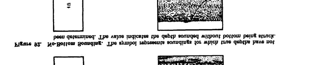
38 12. Coastal Hydrography a. General. Coastal hydrographic features and notes pertinent to those features usually are shown on all sheets showing navigable waters. Sheets showing land areas bordering on inland bodies of water, such as lakes, contain only offshore data. Sheets showing land areas bordering on oceans, seas, bays, or similar bodies of water contain both offshore and foreshore data. b. Definition of Coastal Terms (fig. 82). (1) Coastal hydrographic features. All features within the foreshore and off- shore areas, including permanent cultural and natural features which affect the navigability of the area. (2) Foreshore area. That area which is bare or awash at the hydrographic datum (low water) but which is covered at mean high water. (3) Offshore area. That area which is covered at the hydrographic datum. (4) Hydrographic datum. That stage of low tide to which depths are referred. This varies somewhat in different parts of the world. c. Symbols. The following pages contain the approved symbols for coastal hydrographic features. 29
39 30


40 31

41 32
42 33
43 34
44 13. Roads in the United States on Large- and Medium-Scale Maps a. Road Classifications on Large-scale Maps. Roads within the limits of the United States are classified on large-scale maps as (1) Hard-surface, heavy-duty roads. (a) Four or more lanes wide. (b) Two or three lanes wide. (2) Hard-surface, medium-duty roads. (a) Four or more lanes wide. (b) Two or three lanes wide. (3) Improved, light-duty roads. (4) Unimproved dirt roads. (5) Trails. b. Road Classifications on Medium-Scale Maps. The classifications on medium-scale maps are the same, except for hard-surface roads, where a distinction is made between roads two lanes wide and roads more than two lanes wide. c. Hard-Surface, Heavy-Duty Roads. Roads of this classification carry heavy truck loads in all weather with a minimum of maintenance. The construction is usually of portland-cement concrete, bituminous concrete, or sheet asphalt, rock asphalt, bituminous penetration, or mixed bituminous on a heavy foundation. Brick or block roads are also included in this category. d. Hard-Surface, Medium-Duty Roads. These roads carry medium-heavy truck loads in all weather. Occasional maintenance is required. Construction is usually a bituminous-penetration or mixed-bituminous surface, or bituminoustreated surface on a light foundation. e. Improved, Light-Duty Roads. These roads carry light loads in all weather. Periodic mainte nance is usually necessary. Construction consists of stabilized or oiled-surface gravel or stone, graded and drained gravel or stone, or graded and drained soil surface. Included in this category are hard-surface roads less than two lanes wide and improved private roads which normally are not practical for use in rerouting of traffic in emergencies. f. Unimproved Dirt Roads. These roads are suitable only for light loads in dry weather. They are without surface improvement and are seldom maintained. Included are abandoned roads, fire roads, and lumber roads. g. Trails. The map shows important foot paths, foot trails, and pack trails which can accommodate 1 /4-ton trucks in dry weather. Minor and short connecting trails usually are omitted. h. Symbols. The following pages contain the approved symbols for roads in the United States. 35
45 36
46 37
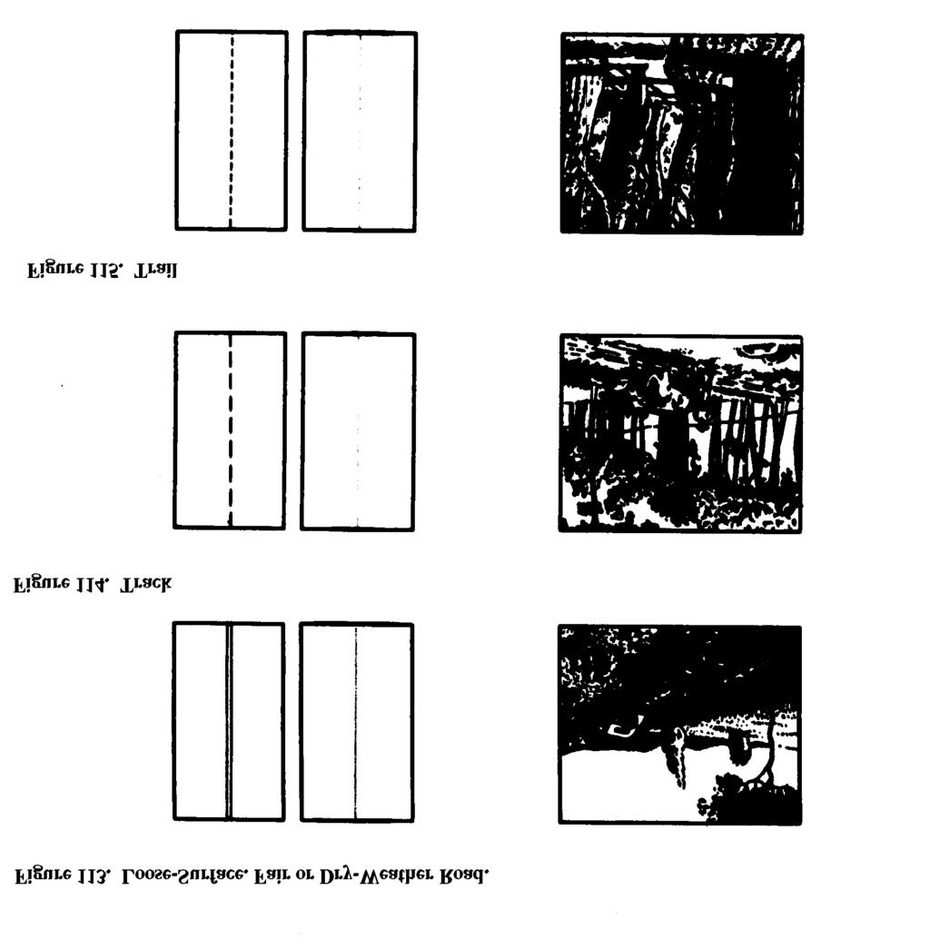
47 14. Roads in Foreign Areas on Large- and Medium-Scale Maps a. Road Classifications. Roads outside the limits of the United States are classified on both large- and medium-scale maps as (1) Hard-surface, all-weather roads. (a) Two or more lanes wide. (b) One lane wide. (2) Loose or light surface, all-weather roads. (a) Two or more lanes wide. (b) One lane wide. (3) Loose surface, fair- or dry-weather roads. (4) Tracks. (5) Trails. b. Hard-Surface, All- Weather Road. These roads carry fairly heavy truck loads in all weather. Minimum maintenance requirements are periodic inspection and repair. The construction is usually concrete or asphaltic concrete, bituminous macadam, surface-treated oiled gravel, and light tar-bound macadam. c. Loose or Light Surface, All-Weather Road. These carry light loads in all weather. The roads generally are drained and graded. Periodic maintenance is required. Construction is usually of gravel, stone, or some stable material, such as sand-clay, on a light foundation. d. Loose Surface, Fair- or Dry- Weather Road. These roads carry light loads in dry weather only. The road may or may not be graded or drained and requires continual maintenance. Any surfacing consists of gravel, or sand-clay with a poor foundation. e. Tracks. Tracks include winter roads, caravan routes, and natural roadways and can accommodate very light vehicles, such as 1 /4-ton trucks, in dry weather. Tracks are normally shown only in areas having poor road systems. f. Trails. Trails include important foot trails, foot paths, and pack trails. Minor trails and unimportant connecting trails are omitted. In areas with good road systems, tracks are included in this category. g. Symbols. The following pages contain the approved symbols for roads in foreign areas. 38
48 39
49 40
50 15. Roads on Small-Scale Maps a. Road Classifications. Roads on small-scale maps are classified as (1) Dual or super highways. (2) Main roads. (3) Secondary roads. (4) Other roads. (5) Tracks or trails. b. Main Roads. Main roads are those which serve as the main thoroughfares between the important populated places of an area. Well alined roads of a substantial width and surface which connect a number of populated places, and cross-country roads which form a direct route connecting with roads and trails leading to important features are included in this category. Main roads are generally hard-surfaced except in areas with poor road systems. c. Secondary Roads. Secondary roads include those roads connecting the minor cities and towns of an area. A road connecting two main roads, at least one of which is higher in classification than the connecting road, is included in this category. In comparison with main roads, secondary roads have less reported use and less substantial construction, and are generally loose-surfaced roads. d. Other Roads. Included in this category are local community roads serving the villages and settlements of an area. Also included are those connecting roads important to the communications network but obviously of a lower classification than the secondary roads. Such roads may be loose-surfaced or dirt roads. e. Tracks or Trails. Tracks and trails are symbolized alike. Both normally are shown only in areas of sparse culture where they supply the only means of communication. Minor tracks and trails are omitted. Included in this category are winter roads and caravan routes. Normally, the roadway is natural with little or no improvements. f. Symbols. The following pages contain the approved symbols for roads on small-scale maps. 41
51 42
52 16. Related Road Features The following symbols indicate eatures related to roads. 43
53 44
54 45
55 17. a. Railroads Gage. (1) Normal gage is the gage used on the majority of the mainline railroads of a country. Normal gage in the United States is standard (4 8 1 /2") gage. (2) Broad gage is any gage greater than the normal gage used in a country. (3) Narrow gage is any gage lesser than the normal gage used in a country. (4) Either the symbol legend in the margin or labeling on the map identifies the gage of the railroads. Multiple-Track Railroad. A multiple-track b. railroad contains three or more mainline tracks paralleling each other. The number of tracks of a multiple-track railroad is indicated by labeling placed parallel to the symbol. c. Nonoperating Railroad. A nonoperating railroad is one not in use. Included in this category are railroads under construction, abandoned railroads, and destroyed railroads. Labeling placed parallel to the symbol indicates whether the line is abandoned, destroyed, or under construction. (1) (2) An abandoned railroad is one which is no longer in use, but the ballast, bridges, and tracks remain in major part and could be put into limited or full operation with a minimum of repair. Only those railroads on which actual work is under way are symbolized as under construction. Proposed lines are not shown. An operating line sometimes has additional tracks under construction. The symbol for the operating line is shown with appropriate labeling to indicate the construction. d. Dismantled Railroad. A dismantled railroad is one which is no longer in use and which has the major part of its tracks and bridges removed. If the right-of-way is being used as a road only, the proper road symbol will be shown. If there is no road and the feature is of landmark importance, it is symbolized by a dashed line and labeled. e. Electrified Railroad. Electrified railroads are shown by the proper symbol indicating the gage and number of tracks, with the word Electrified added parallel to the symbol. f. Developed Areas. (1) (2) (3) Minor line and sidings sometimes are omitted in congested areas. Through lines are always shown. Railroads which run underground for long distances in a city are not shown. The dashed lines indicating tunnels are omitted. Only the headwalls and wings of the tunnel entrances are shown. Rapid transit lines, when located in subways, are not shown. They are shown by the appropriate railroad symbol when located in open cut, on the surface, or on above-surface structures. g. Symbols. The following pages contain the approved symbols for railroads and related features. 46
56 47
57 48
58 49
59 50
60 51
61 18. Features Related to Communications a. Overpasses and Underpasses. On largescale maps, overpasses and underpasses normally are shown wherever they exist. On medium- and small-scale maps they generally are shown only in open areas. An overpass is a short viaduct carrying a road or railroad above the grade of another road or railroad. An underpass is a short tunnel carrying a road or railroad below the grade of another road or railroad. b. Bridges and Viaducts. (1) The distinction between a bridge and a viaduct is that a bridge passes over what is predominantly water while a viaduct passes over what is predominantly land. (2) Long bridges or viaducts are always shown. A shorter bridge or viaduct is shown if it serves as an identifiable landmark or is the only means of crossing within the general area. (3) On long bridges or viaducts, the ends of the symbol appear in their correct locations. On shorter ones, the symbol is merely representative and the ends are not necessarily in their correct locations. (4) Bridges and viaducts less than 20 feet long normally are not shown except when they are underpasses or overpasses. (5) When a bridge is used to carry both a road and a railroad on either the same or different levels, the feature is shown by the road-bridge symbol with the railroad shown to the bridge ends. The symbol is labeled Road and railroad. (6) Footbridges are shown only in areas of sparse culture. c. Drawbridges. (1) Drawbridges are structures of which either the whole or part can be raised, lowered, pivoted, or turned aside to allow or to interrupt traffic. (2) On large-scale maps, the small circle of the symbol is centered on the true location of the center of the movable part of the bridge. d. Ferries. (1) (2) (3) Ferries capable of carrying vehicular or railroad traffic normally are shown wherever they exist. Ferries for pedestrians are shown only in areas of sparse culture or where they provide the only means of watercrossing in the general area. The dashed line connects the points between which the ferry operates, without regard for the actual navigating course of the ferry. Steamship lines are not shown. (4) e. Fords. Fords are shown only in areas of sparse culture or where they provide the only means of water-crossing in the general area. f. Symbols. The following pages contain the approved symbols for features related to communications. 52
62 53
63 54
64 55
65 Buildings and Populated Places on Large- Scale Maps a. Built-Up Areas. (1) A built-up area is a large continuous area which is developed or is in the advanced stage of development for occupancy by concentrated populations. It usually is laid out in a definite street pattern and normally contains a business or industrial district. Since all buildings cannot be shown individually, the area is indicated by an overall screened red tint. (2) Only landmark buildings are shown individually in built-up areas. These are buildings which are prominent because of size, location, or usage, such as government or public buildings, colleges, schools, churches, hospitals, railroad stations, markets, factories, and buildings of historical or cultural interest. (3) Within the general outline of the built-up area, individual symbols are used and the built-up area tint is generally omitted for the following features: (a) Parks and cemeteries equivalent to or larger than one block. (b) Institutions such as colleges, schools, and hospitals possessing o p e n ground areas equivalent to or larger than one block. (c) Section with little construction or development if equivalent to or larger than two blocks. (4) All woodland cover is omitted in builtup areas. b. Native Settlements. These include native settlements in foreign areas in which the buildings are not usually of permanent construction. Kampongs in southwestern Asia and encampments in western Africa are examples. The symbol legend of the map defines the symbol properly. c. Buildings in General. (1) Conventional symbols are used to show a small building or a small structure similar to a building. The symbol is shown in correct orientation and its center usually coincides with the correct location of the center of the structure. (2) Buildings and similar structures whose plotted size exceeds the conventional symbols are shown in correct orientation and shape and usually in correct location. (3) Buildings and structures located along roads are shown in their correct location unless they would then fall within the road. In such cases, the symbol is moved back. (4) In many cases it is impossible to show all buildings because of congestion. The map retains the general shape and pattern of the area and omits the less important buildings. d. Structures Similar to Buildings. (1) These are features of substantial construction not definable as buildings. In many instances they are roofed, although not necessarily enclosed on all sides. The term includes barns, grandstands, railroad sheds, large open sheds, fruit packing sheds, snow sheds, open-air refineries, and similar structures. (2) Structures which are smaller than the average dwelling in the locality are not shown. (3) In foreign areas, when information is unavailable, no distinction is made between buildings and structures similar to buildings. e. Schools and Churches. (1) When a building is used both as a church and a school, it is symbolized as a school. (2) In the United States, the church symbol is used commonly for all denominations. On maps of foreign areas, this symbol usually denotes a Christian place of worship, with other symbols being used to denote places of worship of other sects. In such cases, the marginal symbol legend should be consulted for detailed information. (3) When a school has numerous buildings, the flag symbol is shown only on the administration building or the most prominent building in the group.
66 (4) When there are numerous religious can no longer be used for their original purbuildings in a group, as in a convent pose. Ruins which are smaller than the average or monastery, the cross symbol is dwelling in the locality are not shown unless shown only on the building used for they possess unusual significance. religious services or the most prom- inent building in the group. g. Symbols. The following pages contain the f. Ruins. Ruins are buildings or structures approved symbols for buildings and populated in such a state of dilapidation or decay that they places on large-scale maps. 57
67 58
68 59
69 60
70 61
71 62
72 63
73 20. Buildings and Populated Places on Medium- and Small-Scale Maps a. Reduced Scale. Because of the reduced scale, it is impossible to show the buildings and populated places on medium- and small-scale maps in great detail. Consequently, the symbols are truly symbolic or representative. The only buildings shown are those which serve as outstanding landmarks in isolated areas. b. Populated Places. A small populated place is shown by a small circle. A larger populated place is shown, generally true to shape, by an outlined and tinted area. Within the outline, the only features usually shown are the mainline railroads and through-route roads. On 1:250,000 scale maps, the tint is usually shown in yellow; on small-scale maps, it is shown in red. c. Use of Tinted Squares. In many areas, there is insufficient information available to plot the correct outlines of populated places. In such cases, tinted squares of varying sizes are used as symbols, with the size depending upon the population or importance. Explanation of these squares is contained in the marginal legend of the map. d. Names of Populated Places. The names of populated places are shown in type of varying size, with the size depending upon population or importance. When information is available, the marginal legend shows the different sizes keyed to a population breakdown. When information is not available, the sizes are keyed to an important breakdown. e. Symbols. The following pages contain the approved symbols for buildings and populated places on medium- and small-scale maps. 64
74 65
75 66
76 67
77 21. Industrial and Public Works The following symbols indicate the industrial and public works shown at the various scales. 68
78 69


79 70
80 71
81 72
82 73
83 74
84 75
85 76
86 o 77
87 78
88 22. Control Points and Elevations in some cases, may be less than third order a. Application of Definitions. The definitions accuracy. Whenever information is available. of horizontal and vertical control stations which exceptions are noted in the marginal legend follow are generally applicable only to the of the map. United States. c. Symbols. The following pages contain the b. Exceptions. In foreign areas, horizontal approved symbols for control points and elevacontrol stations may not be monmented and tions. 79
89 80
90 81
91 82
92 23. Boundaries of the symbol is shown. The intervening symbol a. Where two or more boundaries coincide, units are omitted, except where the omission only the symbol representing the higher-ranking would create uncertainty as to the alinement boundary is shown. of the boundary. d. Terminology of boundaries in foreign b. Boundaries which are approximate or areas varies; see the map legend for the correct indefinite are appropriately labeled. terms. c. In cases where a boundary follows a road, e. The following pages contain the approved stream, or river, usually only every third unit symbols for boundaries. 83
93 84
94 I I 85
95 Change 1. Page 86. Paragraphs 23.1 and 23.2 and figures 243 through 332 are added as follows: Joint Operations Graphics a. Purpose and Scope. Joint Operations Graphics are produced in both ground and air versions. The ground version is designated as Series 1501; the air version is designated as Series 1501 AIR. Both versions are designed to provide common base graphics for use in combined operations by the ground and air forces of allied nations. The topographic information is identical on both the ground and air versions. b. Unit of Vertical Measure. On the ground version, elevation and contour values are shown in meters. These values are converted to foot units on the air version. c. Aeronautical Information. Both versions contain identical information regarding aerodromes and obstructions to pilotage. The air version contains additional information concerning aids to air navigation. d. Shaded Relief. Both versions contain an identical representation of shading, to provide a rapid recognition of slope and landforms. The shading also serves as a means of correlating contours and elevations, with emphasis on the more significant terrain features. e. Elevation Tints. Both versions contain a representative system of color tints which depict areas of the same elevation range. A key box on each version indicates the elevation ranges and their corresponding color tints. j. Symbols. The following approved symbols for Joint Operations Graphics are in addition to, or different from, the standard medium-scale symbols shown in figures 1 through 242: 86 (C1-8)
96 C1-9
97 C1-10
98 C1-11
99 C1-12
100 C1-13
101 C1-14
102 C1-15
103 C1-16
104 C1-17
105 C1-18
106 C1-19
107 C1-20
108 C1-21
109 C1-22
110 C1-23
111 C1-24
112 C1-25
113 C1-26
114 C1-27
115 C1-28
116 C1-29
117 C1-30
118 23.2. Pictomaps a. A pictomap is a map on which photographic imagery of a standard photomosaic has been converted into interpretable colors and symbols. b. The components of the pictomap consist of three basic color tones photographically extracted from a photomosaic, masked and drafted symbols, and names data. At the large scales used for city maps (1:5,000 to 1:12,500), the light tones and shadows on the photographic image serve to delineate many of the map features. At scales of 1:25,000 and 1:50,000, however, most planimetric features are shown by drafted symbols, printed in specified colors. c. Tones. The three basic color tones used for area features are as follows: (1) Landtone, a buff-like color tone which represents uncovered earth. (2) Vegetone, green tones which represent densities of vegetation. (3) Shadowtone, a black-green tone which represents shades and shadows. d. Symbols. The following pictomap symbols are different from the standard large-scale symbols shown in figures 1 through 242: C1-31
119 C1-32
120 C1-33
121 C1-34
122 C1-35
123 C1-36
124 C1-37
125 C1-38
126 C1-39

127 C1-40
128 C1-41
129 C1-42
130 C1-43
131 C1-44
132 CHAPTER 3 TOPOGRAPHIC ABBREVIATIONS 24. List of Abbreviations Appendix II contains the list of topographic abbreviations. with their meanings, authorized for use on the standard topographic maps discussed in this manual. 25. Application a. Abbreviations on the face of the map are held to an absolute minimum. They are employed only where space prohibits the use of a full term or where use of the full term would require unreasonable repetition. b. Periods are omitted from abbreviations on the face of the map. In the margin, periods normally are retained. They are, however, omitted from coded abbreviations of governmental agency names. In such cases, no spacing is shown between the coded letters. c. In addition to the abbreviations listed herein, commonly accepted abbreviations of time, measures, and countries are authorized. 87
133 CHAPTER 4 MARGINAL INFORMATION 26. Scope a. This chapter explains the map identifications and other marginal data appearing on topographic maps prepared for use by the Department of the Army. b. These marginal items are illustrated in the charts which appear in appendix III. They are Chart 1 large-scale and 1:100,000 scale maps. Chart 2 medium-scale (except 1 :100,- 000) maps. Chart 3 1:1,000,000 scale maps. c. The arrangement of marginal items will vary. For example, on sheets having a narrow east-west neatline dimension, certain items will appear in the right-hand margin rather than in the lower margin. The composition is generally the same for maps of like scales. d. Detailed information on marginal data will be found in AMS technical manuals and style sheets published under the direction of the Chief of Engineers. 27. Map Identifications a. Purpose. Map identifications are those items appearing in the margins of maps which serve to identify any individual map completely. On maps prepared for the Department of the Army, these identifications are the series name and scale, the series number, the edition number, the sheet name, the sheet number, the unit imprint, and the geographic location name. b. Series Name and Scale. A map series, which normally consists of a common scale of maps which collectively cover a specific area, is generally assigned the geographic or political name of the area covered. The map scale is written as a ratio of map distance to ground distance. Example: GERMANY 1:25, c. Series Number. The series number is a comprehensive reference composed of four and sometimes five elements, usually four numerals or a letter and three numerals. The number is unique for the series. It identifies the area and scale of the series. Example: M841. d. Edition Number. The edition number is a specific identification based on the publication sequence of a particular map. Edition numbers run consecutively; thus, it can be assumed that a map labeled with a higher edition number contains more recent information than another printing with a lower edition number. The edition number also identifies the agency which produced the map. Example: Edition 4-AMS. e. Sheet Name. Generally, a map is named after its outstanding cultural or geographic feature. The name of a cultural feature is customarily chosen, but if a geographic feature is better known than any cultural feature appearing on the map, the geographic name is chosen. Example: FORT KNOX. f. Sheet Number. Sheet numbers for largescale maps are based on an arbitrary geographic coordinate system covering the area to be mapped. The sheet number of a 1:25,000 scale sheet is directly related to the number of a 1 :50,- 000 scale sheet covering the same area, which in turn is directly related to the sheet number of a 1:100,000 scale sheet covering the same area. Sheet numbers for 1:250,000 and 1 :1,000,- 000 scale maps are based on the International Map of the World (IMW) numbering system. Examples: 1:25, III NW; 1:50, III; 1:100, ; 1:250,000 NJ 16-4 ; 1:1,000,000 NJ 16. g. Unit Imprint. The unit imprint is the signature of the agency responsible for printing the map. This is followed by the date identify-
134 ing the particular printing. Example: Printed by Army Map Service, Corps of Engineers, h. Geographic Location Name. The geographic location name indicates the country, state, or general geographic area within which the map lies. The geographic location name includes the sheet name, which is repeated in the lower margin. Large-scale maps of the United States which cover an area entirely within one county or parish, carry the county or parish name below the sheet name and geographic location name. Example: FUJI SAN, JAPAN. i. Refer to Note. In the upper right corner of the map margin, the sheet number and series number are grouped under a note, REFER TO THIS MAP AS. This group provides the primary identification for ordering copies of a map. Example: REFER TO THIS MAP AS: SHEET NJ 16-4 SERIES V501 j. Identification Panels. For quick identification of maps when filed or stacked, identification panels in opposite corners of the map sheet, outside the printed limits of other marginal information, are provided. These panels contain the series number, sheet number, and edition number. Example: SERIES 1301 SHEET NK52 EDITION 2-AMS 28. Other Marginal Data In addition to the identifications described above, the margin of a map contains other information important to the user in evaluating and interpreting the map (table I). a. Credit Note. The credit note aids in evaluating the map and contains interpretive information. The note describes the method of preparation, identifies the source material used in compilation, gives the dates of aerial photography, and lists the source of horizontal and vertical control. It notes whether the map conforms with national map accuracy requirements and whether the map has been field checked. It includes any special information pertinent to the particular sheet. b. Symbol Legend. The symbol legend defines and illustrates the symbols most commonly used such as populated places, roads, and railroads. It also contains symbols for items peculiar to the area being mapped. c. Index to Adjoining Sheets. The index to adjoining sheets, or on 1:250,000 scale maps the location diagram, identifies the surrounding sheets. d. Index to Boundaries. The index to boundaries identifies the political areas appearing in the body of the map. The boundaries in the diagram are schematic but serve as aids in locating the boundaries on the map. On the 1:250,000 scale maps this information is shown in the location diagram. 89
135 e. Coverage Diagram. The coverage diagram, shown on large-scale maps, portrays in graphic form the methods of compilation, notes the dates of any photography used, and identifies and evaluates any maps used as bases. f. Reliability Diagram. The reliability diagram, shown on medium- and small-scale maps, contains graphic references to the reliability of the sources used and identifies the scale, method of survey, and date of the basic sources. g. Datum Notes. The horizontal, vertical, and hydrographic datum notes identify the controls used for these items on the map. Generally, horizontal and hydrographic datum notes are not shown on medium- and small-scale maps. h. Grid Notes and Data. Maps of 1:1,000,- 000 and larger scale contain grid notes and a grid reference box with sample reference, to explain the grid data on the map. Maps carrying 1,000-unit-interval grid lines also show a declination diagram and a protractor scale in the margin. The declination diagram shows the relationship bet wee n true north, magnetic north, and grid north for the major grid at the center of the sheet. Maps carrying 10,000-unitinterval grid lines show a magnetic declination note. This note indicates the variation in the east and west map edges. It also shows the mean annual change. 90
136 APPENDIX I REFERENCES 1. Army Regulations (AR) AR AR AR Military Mapping and Surveying. Dictionary of United States Army Terms. Authorized Abbreviations and Brevity Codes. 2. Department of the Army Pamphlets (DA Pam) DA PAM Index of Army Motion Pictures, Film Strips, Slides and Phono-Recordings. DA PAM Military Publications: Index of Administrative Publications. DA PAM Military Publications: Index of Training Publications. DA PAM Index of Technical Manuals, Technical Bulletins, Supply Bulletins, Lubrication Orders, and Modification Work Orders. DA PAM Military Publications: Index of Graphic Training Aids and Devices. DA PAM Military Publications: Index of Tables of Organization and Equipment, Type Tables of Distribution and Tables of Allowances. DA PAM Military Publications: Index of Supply Manuals, Corps of Engineers. 3. Field Manuals (FM) FM 5-1 FM 5-30 Engineer Troop Organizations and Operations. Engineer Intelligence. FM 21-5 FM 21-6 FM FM FM 30-5 FM FM , Part 1 4. Technical Manuais (TM) TM TM TM TM TM TM TM Military Training. Techniques of Military Instruction. Map Reading. Military Symbols. Combat Intelligence. Terrain Intelligence. Staff Officer s Field Manual: Organization, Technical and Logistical Data. General Drafting. A Guide to the Compilation and Revision of Maps. Multiplex Mapping. Map Reproduction. Foreign Maps. Kit Instruction Map Reading. Tactical Interpretation of Air Photos. 5. Tables of Organization and Equipment TOE 5-55D TOE 5-56D TOE 5-57D TOE 5-59D TOE 5-167C TOE 5-344R Engineer Topographic Battalion, Army. Headquarters and Headquarters Company, Engineer Topographic Battalion, Army. Engineer Map Reproduction and Distribution Company, Army. Engineer Photomapping Company, Army. Engineer Topographic Company, Corps. Engineer Base Map Depot Company. 91
FM DEPARTMENT OF THE ARMY FIELD MANUAL
 FM 21-31 DEPARTMENT OF THE ARMY FIELD MANUAL TOPOGRAPHIC SYMBOLS This copy is a reprint which includes current pages from Change 1. HEADQUARTERS, DEPARTMENT OF THE ARMY APRIL 1961 CHANGE FM 21-31 Cl HEADQUARTERS
CHAPTER 3 MARGINAL INFORMATION AND SYMBOLS
 CHAPTER 3 MARGINAL INFORMATION AND SYMBOLS A map could be compared to any piece of equipment, in that before it is placed into operation the user must read the instructions. It is important that you, as
Land Navigation / Map Reading
 Land Navigation / Map Reading What is the Field Manual for map reading and land navigation? FM 3-25.26 What are the basic colors of a map, and what does each color represent? Black - Indicates cultural
COPYRIGHTED MATERIAL. Contours and Form DEFINITION
 1 DEFINITION A clear understanding of what a contour represents is fundamental to the grading process. Technically defined, a contour is an imaginary line that connects all points of equal elevation above
UNITED STATES MARINE CORPS FIELD MEDICAL TRAINING BATTALION Camp Lejeune, NC
 UNITED STATES MARINE CORPS FIELD MEDICAL TRAINING BATTALION Camp Lejeune, NC 28542-0042 FMST 206 Land Navigation TERMINAL LEARNING OBJECTIVE 1. Given a military topographic map, protractor, and objective,
Introduction to Aerial Photographs and Topographic maps (Chapter 3)
") GEOLOGY 306 Laboratory Instructor: TERRY J. BOROUGHS NAME: Introduction to Aerial Photographs and Topographic maps (Chapter 3) For this assignment you will require: a calculator and metric ruler. Objectives:
GEOLOGY 306 Laboratory Instructor: TERRY J. BOROUGHS NAME: Introduction to Aerial Photographs and Topographic maps (Chapter 3) For this assignment you will require: a calculator and metric ruler. Objectives:
ENVI.2030L Topographic Maps and Profiles
 Name ENVI.2030L Topographic Maps and Profiles I. Introduction A map is a miniature representation of a portion of the earth's surface as it appears from above. The environmental scientist uses maps as
BACKGROUND INFORMATION
 Build an Island INTRODUCTION For this assignment, you will be creating a topographic map and three-dimensional model of a fictional island that you have designed. You will start by exploring some basic
Oakland County Michigan Register of Deeds Plat Engineering, GIS, & Remonumentation Dept. Ph: (248) Fax (248)
 Fax (248)") Oakland County Michigan Register of Deeds Plat Engineering, GIS, & Remonumentation Dept. Ph: (248)-858-1447 Fax (248)-858-7466 Requirements Needed for Final Condominium Approval General Requirements. 1
Oakland County Michigan Register of Deeds Plat Engineering, GIS, & Remonumentation Dept. Ph: (248)-858-1447 Fax (248)-858-7466 Requirements Needed for Final Condominium Approval General Requirements. 1
Surveying & Measurement. Detail Survey Topographic Surveying
 Surveying & Measurement Detail Survey Topographic Surveying Introduction Mapping surveys are made to determine the relief of the earth s surface and locate critical points on it. to determine the locations
STATE UNIVERSITY CONSTRUCTION FUND
 DIRECTIVE 1C-12 Issue date: August 2012 1. General SURVEY, MAPPING AND UTILITY LOCATING This Directive has been developed as a general guide for the survey and mapping effort required for Fund projects.
Introduction to Aerial Photographs and Topographic maps (Chapter 7, 9 th edition) or (chapter 3, 8 th edition)
 or (chapter 3, 8 th edition)") GEOLOGY 306 Laboratory Instructor: TERRY J. BOROUGHS NAME: Introduction to Aerial Photographs and Topographic maps (Chapter 7, 9 th edition) or (chapter 3, 8 th edition) For this assignment you will require:
GEOLOGY 306 Laboratory Instructor: TERRY J. BOROUGHS NAME: Introduction to Aerial Photographs and Topographic maps (Chapter 7, 9 th edition) or (chapter 3, 8 th edition) For this assignment you will require:
Section E NSPS MODEL STANDARDS FOR TOPOGRAPHIC SURVEYS Approved 3/12/02
 Section E NSPS MODEL STANDARDS FOR TOPOGRAPHIC SURVEYS Approved 3/12/02 1. INTRODUCTION This standard is written to provide the professional surveyor (Surveyor) and the client with a guideline for producing
Date Requested, 200_ Work Order No. Funding source Name of project Project limits: Purpose of the project
 Bureau of Engineering SURVEY DIVISION REQUEST FOR TOPOGRAPHIC SURVEY Date Requested, 200_ Work Order No. Funding source Name of project Project limits: Purpose of the project Caltrans involvement (must
Important Questions. Surveying Unit-II. Surveying & Leveling. Syllabus
 Surveying Unit-II Important Questions Define Surveying and Leveling Differentiate between Surveying and Leveling. Explain fundamental Principles of Surveying. Explain Plain and Diagonal Scale. What is
CHAPTER 2C - PRELIMINARY DESIGN. General... 2C-1. Review of Work Load... 2C-2 Establishing Priorities... 2C-2
 SECTION 2C - 1 - PROJECT REVIEW CHAPTER 2C - PRELIMINARY DESIGN General... 2C-1 SECTION 2C - 2 - COORDINATING TIME SCHEDULES Review of Work Load... 2C-2 Establishing Priorities... 2C-2 SECTION 2C 3 - REVIEW
MAP REPRODUCTION GLASS NEGATIVE ENGRAVING
 MAP REPRODUCTION GLASS NEGATIVE ENGRAVING b y D. P. B a r n e t t e, Reproduction Branch U. S. Coast and Geodetic Survey. ( Extracts ) The maimer and method of reproducing on the printed sheet the results
AutoCAD 2016 for Civil Engineering Applications
 Introduction to AutoCAD 2016 for Civil Engineering Applications Learning to use AutoCAD for Civil Engineering Projects Nighat Yasmin Ph.D. SDC P U B L I C AT I O N S Better Textbooks. Lower Prices. www.sdcpublications.com
Lab #4 Topographic Maps and Aerial Photographs
 Lab #4 Topographic Maps and Aerial Photographs Purpose To familiarize you with using topographic maps. Visualizing the shape of landforms from topographic maps is an essential skill in geology. Proficiency
Location Type Description of problem Final text after correction In blue description of changes in illustration Page 2 Suggestion for improvement
 ISOM2017 Corrections The map Commission have during the last year identified some mistakes or less good solutions in the ISOM 2017. Therefore we have started a work to improve the specification. As we
Markville Secondary School Geography Department
 Markville Secondary School Geography Department CGC1D1 Geography of Canada PERFORMANCE TASK - UNIT 1 AND 2 DUE DATE: SEPTEMBER 2011 Parent Signature: CONTOUR MAP AND MODEL The performance task for Geography
Site Plan/Building Permit Review
 Part 6 Site Plan/Building Permit Review 1.6.01 When Site Plan Review Applies 1.6.02 Optional Pre- Application Site Plan/Building Permit Review (hereafter referred to as Site Plan Review) shall be required
Appendix B. Airport Master Plan Update William R. Fairchild International Airport Port Angeles, Washington AIRPORT LAYOUT PLAN CHECKLIST
 APPENDICES Appendix B AIRPORT LAYOUT PLAN CHECKLIST 3 Airport Master Plan Update William R. Fairchild International Airport Port Angeles, Washington September 2011 AC 150/5070-6B (incl. Chg. 1, 5/1/07)
47 CFR Ch. I ( Edition)
") 73.684 should decrease more rapidly with distance beyond the horizon than for Channels 2 6, and modification of the curves for Channels 14 69 may be expected as a result of measurements to be made at a
73.684 should decrease more rapidly with distance beyond the horizon than for Channels 2 6, and modification of the curves for Channels 14 69 may be expected as a result of measurements to be made at a
PHOTOGRAMMETRY STEREOSCOPY FLIGHT PLANNING PHOTOGRAMMETRIC DEFINITIONS GROUND CONTROL INTRODUCTION
 PHOTOGRAMMETRY STEREOSCOPY FLIGHT PLANNING PHOTOGRAMMETRIC DEFINITIONS GROUND CONTROL INTRODUCTION Before aerial photography and photogrammetry became a reliable mapping tool, planimetric and topographic
Airfield Obstruction and Navigational Aid Surveys
 Section I. Section II. Section III. Section IV. Section V. Chapter 7 Airfield Obstruction and Navigational Aid Surveys The purpose of this chapter is to acquaint the Army surveyor with the terminologies
Markville Secondary School Geography Department
 Markville Secondary School Geography Department CGC1D1 Geography of Canada PERFORMANCE TASK - UNITS 1 AND 2 February 2012 DUE DATE: Parent Signature: CONTOUR MAP AND MODEL The performance task for the
PART XII: TOPOGRAPHIC SURVEYS
 PART XII: TOPOGRAPHIC SURVEYS 12.1 Purpose and Scope The purpose of performing topographic surveys is to map a site for the depiction of man-made and natural features that are on, above, or below the surface
PRELIMINARY PLAT CHECK LIST
 Name of Proposed Subdivision: The following items must be included with the initial submittal of a Preliminary Plat: Application, filled out completely Project Narrative Pre-application Conference Report
Minor Site Plan Application and Checklist Land Disturbing Activities
 Minor Site Plan Application and Checklist Land Disturbing Activities INSTRUCTIONS: Please provide the requested information below. The Development Services Department reviews each site plan submittal based
Earth Sciences 089G Short Practical Assignment #4 Working in Three Dimensions
 Earth Sciences 089G Short Practical Assignment #4 Working in Three Dimensions Introduction Maps are 2-D representations of 3-D features, the developers of topographic maps needed to devise a method for
SPECIFICATIONS FOR THE INSTALLATION OF CONDUIT SYSTEMS IN RESIDENTIAL SUBDIVISIONS. Notification of Completed Conduit Sections
 SPECIFICATIONS FOR THE INSTALLATION OF CONDUIT SYSTEMS IN RESIDENTIAL SUBDIVISIONS Section 1 Definitions 2 Scope of Work 3 Extent of Work 4 Inspection and Performance of Work 5 Trenching 6 Duct Installation
CITY OF LA MARQUE CHAPTER GRAPHIC REQUIREMENTS CONSTRUCTION PLAN AND MISCELLANEOUS REQUIREMENTS
 CITY OF LA MARQUE CHAPTER 2 -------------------------------------------- GRAPHIC REQUIREMENTS CONSTRUCTION PLAN AND MISCELLANEOUS REQUIREMENTS CHAPTER 2 ------------------------------------------------
Update: July 20, 2012
 Location and Design Manual, Volume 3 ODOT Office of CADD and Mapping Services Update: July 20, 2012 ** NOTE: All metric references have been removed from this manual. ** PREFACE REVISIONS Glossary of Terms
Shoe Box Activity Constructing a Topographic Map
 Shoe Box Activity Constructing a Topographic Map Background Information All maps are models of some feature of the real world. The kind of map oen used by scientists is called a contour or topographic
Plan Preparation Checklist
 Appendix D Plan Preparation Checklist It is the responsibility of the Designer to complete and submit this checklist along with all required drawings for OUC (EFP) Review. All drawings submitted for OUC
List of Figures. List of Forms
 City of Columbia Engineering Regulations PART 1: SUBMISSION OF PLANS Table of Contents Paragraph Description Page No. 1.1 General 1-1 1.2 Engineer s Report 1-1 1.3 Plans 1-3 1.4 Revisions to Approved Plan
Slope analysis & Grading. Earth shape and earthwork Topographic map Slope form Slope analysis Grading
 6 Slope analysis & Grading Earth shape and earthwork Topographic map Slope form Slope analysis Grading 81 Topographic Map Topographic Contour map Topographic contour map are composed of a series of line
Title: How steep are those hills? Engineering Grade: Estimated Time: 3 hours (2 days) Groups: 3 to 4 students
 Groups: 3 to 4 students") Title: How steep are those hills? Engineering Grade: 10-12 Estimated Time: 3 hours (2 days) Groups: 3 to 4 students Synopsis: Students will be able to understand the concept of surveying and mapping ground
Title: How steep are those hills? Engineering Grade: 10-12 Estimated Time: 3 hours (2 days) Groups: 3 to 4 students Synopsis: Students will be able to understand the concept of surveying and mapping ground
SECTION SITE SURVEYS
 SECTION 02 21 13 SITE SURVEYS SPEC WRITER NOTE: 1. Delete text between // // not applicable to project. Edit remaining text to suit project. 2. Use this section to specify survey required before design
CHAPTER 11 PRELIMINARY SITE PLAN APPROVAL PROCESS
 CHAPTER 11 PRELIMINARY SITE PLAN APPROVAL PROCESS 11.01.00 Preliminary Site Plan Approval 11.01.01 Intent and Purpose 11.01.02 Review 11.01.03 Application 11.01.04 Development Site to be Unified 11.01.05
REQUEST FOR PROPOSAL AERIAL PHOTOGRAPHY & DIGITAL MAPPING ROADS DEPARTMENT
 REQUEST FOR PROPOSAL AERIAL PHOTOGRAPHY & DIGITAL MAPPING ROADS DEPARTMENT The Cherokee Nation is requesting proposals from qualified professionals to provide aerial photography and digital mapping of
HAMILTON TOWNSHIP Department of Planning and Zoning Application for a Commercial / Industrial Site Plan Review
 HAMILTON TOWNSHIP Department of Planning and Zoning Application for a Commercial / Industrial Site Plan Review Date: Application is hereby made for a Site Plan Review for a commercial or industrial use.
Chapter Four AIRPORT LAYOUT PLAN SET COMPONENTS
 The purpose of this chapter is to present the graphic representation of the items addressed and recommended in Chapter Three Demand Capacity Analysis and Facility Requirements (page 3-1). The Airport Layout
CITY OF LOMPOC DEVELOPMENT ASSISTANCE BROCHURE ENCROACHMENT PERMITS AND PUBLIC IMPROVEMENT PLANS
 CITY OF LOMPOC DEVELOPMENT ASSISTANCE BROCHURE E-10 ENCROACHMENT PERMITS AND PUBLIC IMPROVEMENT PLANS The City of Lompoc has determined that the Engineering Division should administer and issue Encroachment
CHECKLIST PRELIMINARY SUBDIVISION AND PRELIMINARY SITE PLAN
 N/A Waiver (1) Four (4) copies of application form. (2) Fifteen (15) copies of plan (3) Subdivision/site plan application fee & professional review escrow deposit (4) Variance application fee & professional
CHAPTER 8 AERIAL PHOTOGRAPHS
 CHAPTER 8 AERIAL PHOTOGRAPHS An aerial photograph is any photograph taken from an airborne vehicle (aircraft, drones, balloons, satellites, and so forth). The aerial photograph has many uses in military
MULTIPLE-FAMILY DESIGN REVIEW SUBMITTAL CHECKLIST
 MULTIPLE-FAMILY DESIGN REVIEW SUBMITTAL CHECKLIST This application lists the content and format of the submittal requirements to initiate the Design Review process. An incomplete application will not be
SPECIAL PUBLIC NOTICE
 SPECIAL PUBLIC NOTICE Draft Map and Drawing Standards for the South Pacific Division Regulatory Program August 6, 2012 Corps contacts: Sacramento District: Michael Finan (916) 557-5324 (Michael.C.Finan@usace.army.mil)
Module 2: Mapping Topic 3 Content: Topographic Maps Presentation Notes. Topographic Maps
 Topographic Maps 1 Take a few moments to study the map shown here of Isolation Peak, Colorado. What land features do you notice? Do you thinking hiking through this area would be easy? Did you see the
EN5308 US ARMY ENGINEER SCHOOL MAP EDITING
 SUBCOURSE EN5308 EDITION 8 US ARMY ENGINEER SCHOOL MAP EDITING MAP EDITING CARTOGRAPHY VIII U.S. Army Topographic Element (DOTD) SUBCOURSE No. EN5308 Six Credit Hours GENERAL The Map Editing subcourse,
TABLE OF CONTENTS 1200 PLAN PREPARATION
 1200 PLAN PREPARATION TABLE OF CONTENTS PAGE 1201 General Plan Sheet Information... 12-1 1201.1 Introduction... 12-1 1201.2 Unit of Measure... 12-1 1201.3 Plan Sheet Materials and File Format... 12-1 1201.4
PLANNING DEPARTMENT SUBMITTAL REQUIREMENTS FOR CONDITIONAL USE PERMITS CLASS 4 DEVELOPMENT REVIEW PROCESS. A. Written Material
 PLANNING DEPARTMENT 970.668.4200 0037 Peak One Dr. PO Box 5660 www.summitcountyco.gov Frisco, CO 80443 SUBMITTAL REQUIREMENTS FOR CONDITIONAL USE PERMITS CLASS 4 DEVELOPMENT REVIEW PROCESS Per the provisions
PRE-LAB for: Introduction to Aerial Photographs and Topographic maps (Ch. 3)
") GEOLOGY 306 Laboratory Instructor: TERRY J. BOROUGHS NAME: PRE-LAB for: Introduction to Aerial Photographs and Topographic maps (Ch. 3) For this assignment you will require: a calculator and metric ruler.
GEOLOGY 306 Laboratory Instructor: TERRY J. BOROUGHS NAME: PRE-LAB for: Introduction to Aerial Photographs and Topographic maps (Ch. 3) For this assignment you will require: a calculator and metric ruler.
Feedback from the Swedish Orienteering Federation regarding the final version of the ISOM 201x
 14 January 2016 Feedback from the Swedish Orienteering Federation regarding the final version of the ISOM 201x General comments If not commented, we agree to the proposed definitions and changes. Three
Maintenance of Traffic sequence of operations including any phasing and detour maps;
 All Local-let projects are required to have a Stage 2 submittal to the LPA Manager for review. The only exceptions are 2-lane resurfacing, striping, guardrail, and raised pavement markers, unless otherwise
B.2 MAJOR SUBDIVISION PRELIMINARY PLAN CHECKLIST
 B.2 MAJOR SUBDIVISION PRELIMINARY PLAN CHECKLIST YES* GENERAL SUBMISSION ITEMS Does the submission include: 1. Thirteen (13) copies of completed Application Form? 2. Thirteen (13) copies of the Preliminary
Application Submittal Checklist for a BASIC USE PERMIT (BUP) Planning & Development Department Planning Division
 Planning & Development Department Planning Division") Application Submittal Checklist for a BASIC USE PERMIT (BUP) APPLICABILITY. This checklist should be used when submitting an application for a Basic Use Permit. When is a Basic Use Permit required? Section
Application Submittal Checklist for a BASIC USE PERMIT (BUP) APPLICABILITY. This checklist should be used when submitting an application for a Basic Use Permit. When is a Basic Use Permit required? Section
SPECIAL PUBLIC NOTICE
 SPECIAL PUBLIC NOTICE Draft Map and Drawing Standards for the South Pacific Division Regulatory Program March 5, 2012 Comment period: ends April 5, 2012 Corps contact: Thomas Cavanaugh (415) 503-6574 (Thomas.J.Cavanaugh@usace.army.mil)
SURVEYING I CENG 383
 SURVEYING I CENG 383 9/21/2011 2 Introduction Definition An art of collecting data for mapping the relative positions of points above, below or on the surface of the earth. Surveying also includes the
SUMMIT COUNTY PLANNING AND ENGINEERING DEPARTMENT
 SUMMIT COUNTY PLANNING AND ENGINEERING DEPARTMENT SINGLE-FAMILY SITE PLAN INFORMATION PACKET GENERAL INFORMATION This information packet explains how your application for a single-family site plan will
This Land Surveying course has been developed by. Failure & Damage Analysis, Inc.
 This Land Surveying course has been developed by Failure & Damage Analysis, Inc. www.discountpdh.com www.pepdh.com Bridge Surveying SURVEYS Bridge surveying is necessary to locate a site, obtain information
TECHNICAL INFORMATION Traffic Template Catalog No. TT1
 Copyright 2016 by SIRCHIE All Rights Reserved. TECHNICAL INFORMATION Traffic Template Catalog No. TT1 INTRODUCTION Your SIRCHIE Traffic Template is a versatile police tool designed to make even the most
Riches of the Earth Guidance Sheet 5
 Riches of the Earth Guidance Sheet 5 www.watershedlandscape.co.uk Recording individual features Several forms of recording are used to give as much information as possible about the feature being recorded.
Mapping The Study Area
 While on the beach you will need to take some measurements to show where the study area is relative to the rest of the world and to show what is inside the study area. Once the measurements have been taken,
CONCEPT REVIEW GUIDELINES
 Department of Planning & Community Development @ Jefferson Station 1526 E. Forrest Avenue Suite 100 East Point, GA 30344 404.270.7212 (Phone) 404.765.2784 (Fax) www.eastpointcity.org CONCEPT REVIEW GUIDELINES
Site Plan Review Application. Interest in the Property (e.g. fee simple, land option, etc.)
") 1. Identification CITY OF FENTON 301 South Leroy Street Fenton, Michigan 48430-2196 (810) 629-2261 FAX (810) 629-2004 Site Plan Review Application Project Name Applicant Name Address City/State/Zip Phone
1. Identification CITY OF FENTON 301 South Leroy Street Fenton, Michigan 48430-2196 (810) 629-2261 FAX (810) 629-2004 Site Plan Review Application Project Name Applicant Name Address City/State/Zip Phone
Guidance Material for ILS requirements in RSA
 Guidance Material for ILS requirements in RSA General:- Controlled airspace required with appropriate procedures. Control Tower to have clear and unobstructed view of the complete runway complex. ATC to
NJDEP GPS Data Collection Standards for GIS Data Development
 NJDEP GPS Data Collection Standards for GIS Data Development Bureau of Geographic Information Systems Office of Information Resource Management April 24 th, 2017 Table of Contents 1.0 Introduction... 3
Topographic Maps. Contour Lines
 Topographic Maps Our first task today will consist of locating ourselves with the help of a topographic map. GPS units that can tell you the location of any Dunkin' Donuts within a five mile radius. Paper
Photo Scale The photo scale and representative fraction may be calculated as follows: PS = f / H Variables: PS - Photo Scale, f - camera focal
 Scale Scale is the ratio of a distance on an aerial photograph to that same distance on the ground in the real world. It can be expressed in unit equivalents like 1 inch = 1,000 feet (or 12,000 inches)
Hillside & Foothills Development Application
 Hillside & Foothills Development Application This box for office use only File #: Cross Referenced File(s): Fee: Zone(s): Are Pre-Application materials attached? Yes No This application is a request to
Chapter 23. Signing and Pavement Marking Plans
 Chapter 23 Signing and Pavement Marking Plans 23.1 General... 23-3 23.2 Key Sheet... 23-4 23.3 Signature Sheet... 23-4 23.4 Tabulation of Quantities and Pay Item Notes... 23-4 23.4.1 Standard Notes...
MINIMUM DRAWING REQUIREMENTS FOR WATER AND SEWER LINE PROJECTS
 Public Works Department Water & Wastewater Services WATER & WASTEWATER ENGINEERING DIVISION 2555 West Copans Road Pompano Beach, Florida 33369 954-831-0745 FAX 954-831-0798/0925 MINIMUM DRAWING REQUIREMENTS
Maps and map interpretation An introduction for geoscientists
 Maps and map interpretation An introduction for geoscientists Produced by the University of Derby in conjunction with UKOGL Aims This teaching package provides an introduction to maps and how to identify
SUBMITTAL REQUIREMENTS FOR USE PROCESS III OR PROCESS IV
 COMMUNITY DEVELOPMENT DEPARTMENT 33325 8 th Avenue South Federal Way WA 98003 253-835-2607; Fax 253-835-2609 www.cityoffederalway.com SUBMITTAL REQUIREMENTS FOR USE PROCESS III OR PROCESS IV USE PROCESS
CITY OF MUSKEGO DRAFTING STANDARDS
 CITY OF MUSKEGO DRAFTING STANDARDS GENERAL - These standards apply to all plans. 1. Plans must be prepared on sheets measuring 36 inch across and 22 inch to 24 inch high unless otherwise specified under
2. CHARTS. 2.1 Chart projections Mercator projections. Maps which are used for marine or aeronautical navigation are called charts.
 Maps which are used for marine or aeronautical navigation are called charts. In Canadian waters, mariners are required to carry the latest editions of the paper charts, at the largest scale available (see
Volume 1 - Module 6 Geometry of Aerial Photography. I. Classification of Photographs. Vertical
 RSCC Volume 1 Introduction to Photo Interpretation and Photogrammetry Table of Contents Module 1 Module 2 Module 3.1 Module 3.2 Module 4 Module 5 Module 6 Module 7 Module 8 Labs Volume 1 - Module 6 Geometry
Chapter 3: Assorted notions: navigational plots, and the measurement of areas and non-linear distances
 : navigational plots, and the measurement of areas and non-linear distances Introduction Before we leave the basic elements of maps to explore other topics it will be useful to consider briefly two further
SECTION 3 IMPROVEMENT PLAN REQUIREMENTS
 SECTION 3 IMPROVEMENT PLAN REQUIREMENTS CONTENTS Page 3-1 Digital Submittals 3-2 3-2 Paper Size and Scale 3-2 3-3 Drafting Standard 3-2 3-4 Title Sheet 3-2 3-5 Title Block 3-3 3-6 Drainage, Sewer, Water,
For crossing under a railroad, contact the specific railroad company's engineering department.
 PAGE 330524-1 SECTION 330524 SPECIFIER: This section is for the underground installation of piping by directional drilling. When specifying this method of piping installation, care must be taken to ensure
AERIAL PHOTOGRAPHS CHAPTER 8
 CHAPTER 8 AERIAL PHOTOGRAPHS An aerial photograph is any photograph taken from an airborne vehicle (aircraft, drones, balloons) satellites, and so forth). The aerial photograph has many uses in military
TOPOGRAPHIC MAPS A NEW WAY TO VIEW THE WORLD!
 TOPOGRAPHIC MAPS A NEW WAY TO VIEW THE WORLD! http://courtneyjennings.weebly.com/unit-4---weathering-erosiontopo-maps-past.html A topographic map, simply put, is a two-dimensional representation of a portion
Large Scale Photogrammetric Maps for Land Planning
 Large Scale Photogrammetric Maps for Land Planning A lva F. W arren Clyde E. Williams & Associates, Inc. South Bend, Indiana Introduction It is my purpose to give a brief explanation of the method of making
City of Massillon Site Plan Checklist
 City of Massillon Site Plan Checklist The following information MUST be included with all Site Plans submitted for review and processing in order to constitute a complete Site Plan Package. Incomplete
QUANTITY SURVEYS. Introduction
 QUANTITY SURVEYS Introduction In engineering surveying, we often consider a route (road, sewer pipeline, channel, etc.) from three distinct perspectives. The plan view of route location is the same as
Appendix 10 Business City Centre Zone building in relation to boundary
 Appendix 10 Business City Centre Zone building in relation to boundary The following explanation is divided into two parts: Part 1. A preliminary explanation of the nature of the indicator system and why
CHAPTER 1: TITLE SHEET and GENERAL LAYOUT
 CHAPTER 1: TITLE SHEET and GENERAL LAYOUT AREA OF ENVIRONMENTAL SENSITIVITY It is important to show the areas of environmental sensitivity in the plan to make sure these areas are not impacted. These locations
East Bay Municipal Utility District. Study Guide for Survey Technician I
 East Bay Municipal Utility District Study Guide for Survey Technician I Summer 2018 TABLE OF CONTENTS PAGE Introduction... 1 Scoring... 1 Visual Perception... 2 Sample Questions 1-2... 2 Reading and Interpreting
WILTON MANORS, Island City 2020 WILTON DRIVE, WILTON MANORS, FLORIDA 33305
 WILTON MANORS, Island City 2020 WILTON DRIVE, WILTON MANORS, FLORIDA 33305 COMMUNITY DEVELOPMENT SERVICES (954) 390-2180 FAX: (954) 567-6069 This package includes: General Submittal Procedures Submittal
SECTION EDITION - REVISION 2. Large Guide
 SECTION 4 0 EDITION - REVISION Large Guide March 017 (This page left intentionally blank) Guide Sign Design Guidelines Design Guidelines There are general guidelines to follow in the design of highway
CHAPTER 11 SURVEY CADD
 CHAPTER 11 SURVEY CADD Chapter Contents Sec. 11.01 Sec. 11.02 Sec. 11.03 Sec. 11.04 Sec. 11.05 Sec. 11.06 Sec. 11.07 Sec. 11.08 Sec. 11.09 Sec. 11.10 General Description of Survey File Contents of Survey
Existing and proposed contours at 1-foot intervals. The fill and/or excavation quantities in cubic yards.
 PLAN REQUIREMENTS The plans for street design shall conform to the requirements of Sections 3 and 4. The following requirements shall also be shown on the plans where applicable. Road and Storm Plans:
IOF Sprint Map Seminar Riga, 11 th /12 th March 2016
 IOF Sprint Map Seminar Riga, 11 th /12 th March 2016 Day 1 Sprint Clinic Riga 18:00-18:30 Introduction Thomas Gloor 18:30-19:15 Presentation - how to draw maps? Thomas Gloor 19:15 21:00 Correct usage of
EXAMPLES OF OBJECT-ORIENTED CLASSIFICATION PERFORMED ON HIGH-RESOLUTION SATELLITE IMAGES
 EXAMPLES OF OBJECT-ORIENTED CLASSIFICATION... 349 Stanisław Lewiński, Karol Zaremski EXAMPLES OF OBJECT-ORIENTED CLASSIFICATION PERFORMED ON HIGH-RESOLUTION SATELLITE IMAGES Abstract: Information about
APPLICATION FOR PLANNED UNIT DEVELOPMENT (PUD) DEVELOPMENT PLAN
 DEVELOPMENT PLAN") 209 S. Main Street Marysville, Ohio 43040 Phone: (937) 645-7350 Fax: (937) 645-7351 www.marysvilleohio.org APPLICATION FOR PLANNED UNIT DEVELOPMENT (PUD) DEVELOPMENT PLAN *** IMPORTANT INFORMATION ~ Please
209 S. Main Street Marysville, Ohio 43040 Phone: (937) 645-7350 Fax: (937) 645-7351 www.marysvilleohio.org APPLICATION FOR PLANNED UNIT DEVELOPMENT (PUD) DEVELOPMENT PLAN *** IMPORTANT INFORMATION ~ Please
DEPARTMENT OF DEFENSE STANDARD PRACTICE. DMA SINGLE COLOR OVERPRINT REVISION UPDATES (sco)
") Gm=J MIL-STD-6000 18 MARCH 1992 Note - The cover page of this standard has been changed for administrative reasons. There are no other changes to this document. DEPARTMENT OF DEFENSE STANDARD PRACTICE
Gm=J MIL-STD-6000 18 MARCH 1992 Note - The cover page of this standard has been changed for administrative reasons. There are no other changes to this document. DEPARTMENT OF DEFENSE STANDARD PRACTICE
Recommended Changes to the Public Hearing Draft Zoning Ordinance
 DATE: December 6, 2016 TO: Village of Oak Park FROM: Arista Strungys SUBJECT: Recommended Changes Recommended Changes to the Public Hearing Draft Zoning Ordinance ZONING MAP» Edit to remove right-of-way
A. Section includes administrative and procedural requirements for project record documents, including the following:
 SECTION 017839 - PROJECT RECORD DOCUMENTS PART 1 - GENERAL 1.1 RELATED DOCUMENTS A. Drawings and general provisions of the Contract, including General and Supplementary Conditions and other Division 01