Introduction to Radio Astronomy!
|
|
|
- Martin Hall
- 5 years ago
- Views:
Transcription
1 Introduction to Radio Astronomy! Sources of radio emission! Radio telescopes - collecting the radiation! Processing the radio signal! Radio telescope characteristics! Observing radio sources
2 Sources of Radio Emission Blackbody (thermal)! Continuum sources (non-thermal)! Spectral line sources!
3 Blackbody Sources: The cosmic microwave background, the planets! Obs in cm requires low temperature: λ m T = cm K Flux = const ν α T! For thermal sources α is ~2 (flatter for less opaque sources)!

4

5 Continuum (non-thermal) Emission: Emission at all radio wavelengths! Bremsstralung (free-free):! Electron is accelerated as it passes a charged particle thereby emitting a photon! Synchrotron:! A charged particle moving in a magnetic field experiences acceleration and emits a photon!


6 Sources of Continuum Emission!
7 Radio Emission Lines! Neutral hydrogen (HI) spin-flip transition! Recombination lines (between high-lying atomic states)! Molecular lines (CO, OH, etc.)!
8 21cm Line of Neutral Hydrogen! Not only are λ, ν, and E equivalent, but for the most part velocity and distance are as well. z = λ λ 0 λ 0 = Δv c d = v /H 0 Intensity Wavelength
!")
9 21cm Line of Neutral Hydrogen, cont.! HI spectral line from galaxy! Shifted by expansion of universe ( recession velocity )! Broadened by rotation!


10 21 cm Line Emission: The M81 Group! Stellar Light Neutral Hydrogen Yun et al.
11 Radio Telescopes! Karl Jansky, Holmdel NJ, 1929
12 Antennas! Device for converting electromagnetic radiation into electrical currents or vice-versa.! Often done with dipoles or feedhorns.! The most basic telescopes are antennas + electronics! Karl Jansky, Holmdel NJ, 1929

13 Radio Telescope Components! Reflector(s)! Feed horn(s)! Low-noise amplifier! Filter! Downconverter! IF Amplifier! Spectrometer!

14 Reflector! Increases the collecting area! Increases sensitivity! Increases resolution! Must keep all parts of on-axis plane wavefront in phase at focus! Spherical surface focuses to a line! 430 MHz line feed!


15 Antenna/Feedhorn Hardware that takes the signal from the antenna to the electronics Array of 7 feedhorns on the! Arecibo telescope - ALFA sources! Typical cm-wave feedhorn!
16 Fourier Transforms and Beam Patterns!


17 Radio Telescope Characteristics beam and sidelobes! Diffraction pattern of telescope sinθ = 1.22 (λ/d) Diffraction pattern indicates sensitivity to sources on the sky! Uniformly illuminated circular aperture: central beam & sidelobe rings! FWHM of central beam is called the beamwidth! Note that you are sensitive to sources away from beam center
18 Radio Telescope Characteristics power and gain The power collected by an antenna is approximately:! P=S A Δν S = flux at Earth, A = antenna area, Δν = frequency interval or bandwidth of measured radiation! The gain of an antenna is given by:! G=4πA/λ 2 Aperture efficiency is the ratio of the effective collecting area to the actual collecting area!
19 Signal Path! Amplify signal Low-Noise Amplifier Set bandwidth Filter Shift frequency Downconverter Analyze spectrum Spectrometer IF Amplifier Amplify signal at new frequency Local Oscillator
20 Mixers signal mixed signal LO original signal 0 Hz frequency
21 The Signal Path Signal MUCH small than thermal noise so strong amplification and stable receivers are required Variations in amplifier gain monitored and corrected using switching techniques: between sky and reference source between object and ostensibly empty sky between frequency of interest and neighboring passband. Smaller frequencies are much more convenient for the electronics so signal is downconverted
22
23 Signal Path! Amplify signal Low-Noise Amplifier Set bandwidth Filter Shift frequency Downconverter Analyze spectrum Spectrometer IF Amplifier Amplify signal at new frequency Local Oscillator
24 Autocorrelation Spectrometer Or how we actually make sense out of the signal! Measures the fourier transform of the power spectrum! Special-purpose hardware computes the correlation of the signal with itself: R n = Ν 1 Σ 1 N [υ(t j )υ(t j +nδt)] where δt is lag and υ is signal voltage; integer n ranges from 0 to (δt δf) -1 if frequency channels of width δf are required! Power spectrum is discrete Fourier transform (FFT) of R n!
25 Spectral Resolution! The spectral resolution in a radio telescope can be limited by several issues:! integration time (signal-to-noise)! filter bank resolution (if youʼre using a filter bank to generate a power spectrum in hardware)
26 Radio Telescope Characteristics sensitivity Sensitivity is a measure of the relationship between the signal and the noise! Signal: the power detected by the telescope! Noise: mostly thermal from electronics but also ground radiation entering feedhorn and the cosmic microwave background. Poisson noise is ALWAYS important. Interference is also a HUGE problem (radar, GPS, etc.)!
27 Radiometer Equation T rms = α T sys / Δνt T rms = rms noise in observation α ~ (2) 1/2 because half of the time is spent off the source off-source = position switch off-frequency = frequency switch T sys = System temperature Δν = bandwidth, i.e., frequency range observed t = integration time Intensity Wavelength
28 Radio Telescope Characteristics semantics Preferred unit of flux density: (requires calibration) is Jansky:! 1Jy = W m -2 Hz -1! Brightness: Flux density per unit solid angle. Brightness of sources are often given in temperature units!
29 Radio Telescope Characteristics Temperatures In radio astronomy power is often measured in temperature - the equivalent temperature of a blackbody producing the same power! System temperature: temperature of blackbody producing same power as telescope + instrumentation without a source! Brightness temperature: Flux density per unit solid angle of a source measured in units of equivalent blackbody temperature! Antenna temperature: The flux density transferred to the receiver by the antenna. Some of the incoming power is lost, represented by the aperture efficiency!
30 Radio Telescope Characteristics polarization H I sources are un-polarized! Synchrotron sources are often polarized E-field in plane of electronʼs acceleration! Noise sources (man-made interference) are often polarized! Each receiver can respond to one polarization one component of linear or one handedness of circular polarization! Usually there are multiple receivers to observe both polarization components simultaneously!
31 Parameterization of Polarization Linear E x and E y with phase difference φ Stokesʼ parameters:! I = E x 2 + E y 2! Q = E x 2 - E y 2! U = 2E x E y cosφ! V = 2E x E y sinφ! Unpolarized source: E x = E y and φ = 0! Un-polarized Q = 0, V = 0, and I = U;! Stokesʼ I = total flux (sum of x and y polarizations)!
32 Observing Schemes! Total scan time [per] target will be 7 minutes using the LBW! On-source/off-source data collection technique! LBW receiver will track source as it moves across the sky.! In order to flat field the image, data is taken over a period of blank sky (the off source) over the same altitude and azimuth path traveled by the target (the on source).! 3 min. on source, 1 min. to move back, 3 min. off source.! The differences in the two passes provides corrections for local environmental noise as well as background sky noise using bandpass subtraction.! The spectra will be analyzed with an interim 50 MHz correlator.! LBW samples two orthogonal polarization states which can be treated independently in this stage of analysis.!
33 Observing Schemes! Position switching helps remove systematics in data! Reduced spectrum = (ON-OFF)/OFF! ON: Target source observation! OFF: blank sky observed over the same altitude and azimuth path traveled by target (on source).! corrections for local environmental noise as well as background sky noise! Two polarizations can be compared to identify RFI or averaged to improve signal for an unpolarized source!
34 Happy Observing!!!
35 Baselines and Observing Schemes! Instrumental effects cause variations in the baseline that are often much larger than the signal that we want to measure! We need to find a way to observe with and without the source but without changing the instrumental effects! We usually accomplish the above with either beam (position) switching or frequency switching!

36 Baselines Raw baseline shape for a 21 cm observation with Arecibo! Red line is over the Milky Way emission!
37 Baselines and Observing Schemes! Instrumental effects cause variations in the baseline that are often much larger than the signal that we want to measure! We need to find a way to observe with and without the source but without changing the instrumental effects! We usually accomplish the above with either beam (position) switching or frequency switching!
38 ALFALFA Observing Technique: HI 21 cm Observing in Action Drift scan: telescope is fixed, the position change is driven by the rotation of the Earth! Baseline shape is removed using spectra that are adjacent in time and space! Because the telescope does not move, the systematic noise does not change making the data easier to correct!
Fundamentals of Radio Astronomy. Lyle Hoffman, Lafayette College ALFALFA Undergraduate Workshop Arecibo Observatory, 2008 Jan. 13
 Fundamentals of Radio Astronomy Lyle Hoffman, Lafayette College ALFALFA Undergraduate Workshop Arecibo Observatory, 2008 Jan. 13 Outline Sources in brief Radiotelescope components Radiotelescope characteristics
Introduction to Radio Astronomy
 Introduction to Radio Astronomy The Visible Sky, Sagittarius Region 2 The Radio Sky 3 4 Optical and Radio can be done from the ground! 5 Outline The Discovery of Radio Waves Maxwell, Hertz and Marconi
Introduction to Radio Astronomy. Richard Porcas Max-Planck-Institut fuer Radioastronomie, Bonn
 Introduction to Radio Astronomy Richard Porcas Max-Planck-Institut fuer Radioastronomie, Bonn 1 Contents Radio Waves Radio Emission Processes Radio Noise Radio source names and catalogues Radio telescopes
A Crash Course in Radio Astronomy and Interferometry: 1. Basic Radio/mm Astronomy
 A Crash Course in Radio Astronomy and Interferometry: 1. Basic Radio/mm Astronomy James Di Francesco National Research Council of Canada North American ALMA Regional Center Victoria (thanks to S. Dougherty,
Receiver Performance and Comparison of Incoherent (bolometer) and Coherent (receiver) detection
 and Coherent (receiver) detection") At ev gap /h the photons have sufficient energy to break the Cooper pairs and the SIS performance degrades. Receiver Performance and Comparison of Incoherent (bolometer) and Coherent (receiver) detection
At ev gap /h the photons have sufficient energy to break the Cooper pairs and the SIS performance degrades. Receiver Performance and Comparison of Incoherent (bolometer) and Coherent (receiver) detection
Submillimeter (continued)
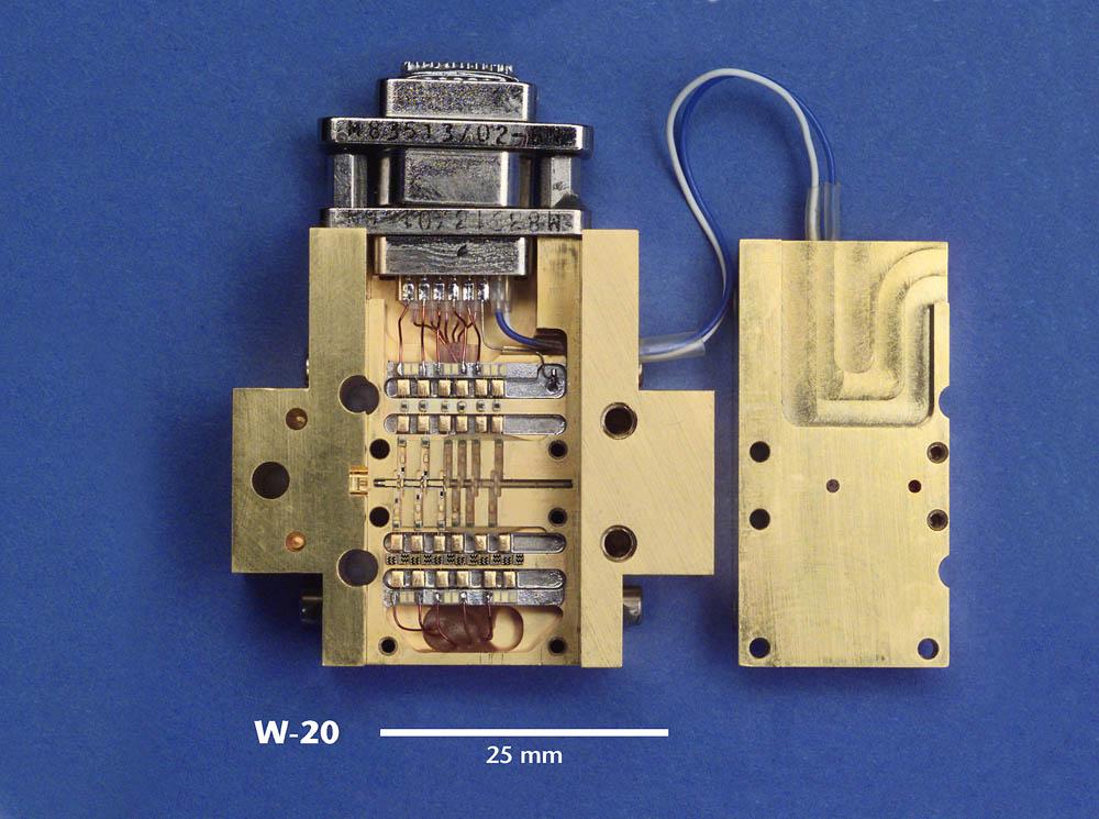
") Submillimeter (continued) Dual Polarization, Sideband Separating Receiver Dual Mixer Unit The 12-m Receiver Here is where the receiver lives, at the telescope focus Receiver Performance T N (noise temperature)
Submillimeter (continued) Dual Polarization, Sideband Separating Receiver Dual Mixer Unit The 12-m Receiver Here is where the receiver lives, at the telescope focus Receiver Performance T N (noise temperature)
More Radio Astronomy
 More Radio Astronomy Radio Telescopes - Basic Design A radio telescope is composed of: - a radio reflector (the dish) - an antenna referred to as the feed on to which the radiation is focused - a radio
Guide to observation planning with GREAT
 Guide to observation planning with GREAT G. Sandell GREAT is a heterodyne receiver designed to observe spectral lines in the THz region with high spectral resolution and sensitivity. Heterodyne receivers
What does reciprocity mean
 Antennas Definition of antenna: A device for converting electromagnetic radiation in space into electrical currents in conductors or vice-versa. Radio telescopes are antennas Reciprocity says we can treat
Signal Flow & Radiometer Equation. Aletha de Witt AVN-Newton Fund/DARA 2018 Observational & Technical Training HartRAO
 Signal Flow & Radiometer Equation Aletha de Witt AVN-Newton Fund/DARA 2018 Observational & Technical Training HartRAO Understanding Radio Waves The meaning of radio waves How radio waves are created -
Astronomische Waarneemtechnieken (Astronomical Observing Techniques)
") Astronomische Waarneemtechnieken (Astronomical Observing Techniques) 7 th Lecture: 15 October 01 1. Introduction. Radio Emission 3. Observing 4. Antenna Technology 5. Receiver Technolgy 6. Back Ends 7.
Astronomische Waarneemtechnieken (Astronomical Observing Techniques) 7 th Lecture: 15 October 01 1. Introduction. Radio Emission 3. Observing 4. Antenna Technology 5. Receiver Technolgy 6. Back Ends 7.
Sources classification
 Sources classification Radiometry relates to the measurement of the energy radiated by one or more sources in any region of the electromagnetic spectrum. As an antenna, a source, whose largest dimension
Spectral Line Bandpass Removal Using a Median Filter Travis McIntyre The University of New Mexico December 2013
 Spectral Line Bandpass Removal Using a Median Filter Travis McIntyre The University of New Mexico December 2013 Abstract For spectral line observations, an alternative to the position switching observation
Introduction to DSTV Dish Observations. Alet de Witt AVN Technical Training 2016
 Introduction to DSTV Dish Observations Alet de Witt AVN Technical Training 2016 Outline Theory: - Radio Waves - Radio Telescope Antennas - Angular Sizes - Brightness Temperature and Antenna Temperature
Multiplying Interferometers
 Multiplying Interferometers L1 * L2 T + iv R1 * R2 T - iv L1 * R2 Q + iu R1 * L2 Q - iu Since each antenna can output both L and R polarization, all 4 Stokes parameters are simultaneously measured without
Spectral Line Imaging
 ATNF Synthesis School 2003 Spectral Line Imaging Juergen Ott (ATNF) Juergen.Ott@csiro.au Topics Introduction to Spectral Lines Velocity Reference Frames Bandpass Calibration Continuum Subtraction Gibbs
The Cosmic Microwave Background Radiation B. Winstein, U of Chicago
 The Cosmic Microwave Background Radiation B. Winstein, U of Chicago Lecture #1 Lecture #2 What is it? How its anisotropies are generated? What Physics does it reveal? How it is measured. Lecture #3 Main
Antennas. Greg Taylor. University of New Mexico Spring Astronomy 423 at UNM Radio Astronomy
 Antennas Greg Taylor University of New Mexico Spring 2011 Astronomy 423 at UNM Radio Astronomy Radio Window 2 spans a wide range of λ and ν from λ ~ 0.33 mm to ~ 20 m! (ν = 1300 GHz to 15 MHz ) Outline
EVLA System Commissioning Results
 EVLA System Commissioning Results EVLA Advisory Committee Meeting, March 19-20, 2009 Rick Perley EVLA Project Scientist t 1 Project Requirements EVLA Project Book, Chapter 2, contains the EVLA Project
Antennas & Receivers in Radio Astronomy
 Antennas & Receivers in Radio Astronomy Mark McKinnon Fifteenth Synthesis Imaging Workshop 1-8 June 2016 Purpose & Outline Purpose: describe how antenna elements can affect the quality of images produced
Antennas and Receivers in Radio Astronomy
 Antennas and Receivers in Radio Astronomy Mark McKinnon Eleventh Synthesis Imaging Workshop Socorro, June 10-17, 2008 Outline 2 Context Types of antennas Antenna fundamentals Reflector antennas Mounts
J/K). Nikolova
. Nikolova") Lecture 7: ntenna Noise Temperature and System Signal-to-Noise Ratio (Noise temperature. ntenna noise temperature. System noise temperature. Minimum detectable temperature. System signal-to-noise ratio.)
Lecture 7: ntenna Noise Temperature and System Signal-to-Noise Ratio (Noise temperature. ntenna noise temperature. System noise temperature. Minimum detectable temperature. System signal-to-noise ratio.)
Observational Astronomy
 Observational Astronomy Instruments The telescope- instruments combination forms a tightly coupled system: Telescope = collecting photons and forming an image Instruments = registering and analyzing the
Chapter 23 Electromagnetic Waves Lecture 14
 Chapter 23 Electromagnetic Waves Lecture 14 23.1 The Discovery of Electromagnetic Waves 23.2 Properties of Electromagnetic Waves 23.3 Electromagnetic Waves Carry Energy and Momentum 23.4 Types of Electromagnetic
Commissioning Report for the ATCA L/S Receiver Upgrade Project
 Commissioning Report for the ATCA L/S Receiver Upgrade Project N. M. McClure-Griffiths, J. B. Stevens, & S. P. O Sullivan 8 June 211 1 Introduction The original Australia Telescope Compact Array (ATCA)
Antennas. Greg Taylor. University of New Mexico Spring Astronomy 423 at UNM Radio Astronomy
 Antennas Greg Taylor University of New Mexico Spring 2017 Astronomy 423 at UNM Radio Astronomy Outline 2 Fourier Transforms Interferometer block diagram Antenna fundamentals Types of antennas Antenna performance
GBT Spectral Baseline Investigation Rick Fisher, Roger Norrod, Dana Balser (G. Watts, M. Stennes)
") GBT Spectral Baseline Investigation Rick Fisher, Roger Norrod, Dana Balser (G. Watts, M. Stennes) Points to Note: Wider bandwidths than were used on 140 Foot Cleaner antenna so other effects show up Larger
GBT Spectral Baseline Investigation Rick Fisher, Roger Norrod, Dana Balser (G. Watts, M. Stennes) Points to Note: Wider bandwidths than were used on 140 Foot Cleaner antenna so other effects show up Larger
Coherent Receivers Principles Downconversion
 Coherent Receivers Principles Downconversion Heterodyne receivers mix signals of different frequency; if two such signals are added together, they beat against each other. The resulting signal contains
To print higher-resolution math symbols, click the Hi-Res Fonts for Printing button on the jsmath control panel.
 To print higher-resolution math symbols, click the Hi-Res Fonts for Printing button on the jsmath control panel. Radiometers Natural radio emission from the cosmic microwave background, discrete astronomical
LE/ESSE Payload Design
 LE/ESSE4360 - Payload Design 4.3 Communications Satellite Payload - Hardware Elements Earth, Moon, Mars, and Beyond Dr. Jinjun Shan, Professor of Space Engineering Department of Earth and Space Science
A Quick Review. Spectral Line Calibration Techniques with Single Dish Telescopes. The Rayleigh-Jeans Approximation. Antenna Temperature
 Spectral Line Calibration Techniques with Single Dish Telescopes A Quick Review K. O Neil NRAO - GB A Quick Review A Quick Review The Rayleigh-Jeans Approximation Antenna Temperature Planck Law for Blackbody
Antenna and Noise Concepts
 Antenna and Noise Concepts 1 Antenna concepts 2 Antenna impedance and efficiency 3 Antenna patterns 4 Receiving antenna performance Levis, Johnson, Teixeira (ESL/OSU) Radiowave Propagation August 17, 2018
EVLA Memo #119 Wide-Band Sensitivity and Frequency Coverage of the EVLA and VLA L-Band Receivers
 EVLA Memo #119 Wide-Band Sensitivity and Frequency Coverage of the EVLA and VLA L-Band Receivers Rick Perley and Bob Hayward January 17, 8 Abstract We determine the sensitivities of the EVLA and VLA antennas
Phased Array Feeds A new technology for wide-field radio astronomy
 Phased Array Feeds A new technology for wide-field radio astronomy Aidan Hotan ASKAP Project Scientist 29 th September 2017 CSIRO ASTRONOMY AND SPACE SCIENCE Outline Review of radio astronomy concepts
Experiment 5: Spark Gap Microwave Generator Dipole Radiation, Polarization, Interference W14D2
 Experiment 5: Spark Gap Microwave Generator Dipole Radiation, Polarization, Interference W14D2 1 Announcements Week 14 Prepset due Fri at 8:30 am PS 11 due Week 14 Friday at 9 pm in boxes outside 26-152
RECOMMENDATION ITU-R S.733-1* (Question ITU-R 42/4 (1990))**
)**") Rec. ITU-R S.733-1 1 RECOMMENDATION ITU-R S.733-1* DETERMINATION OF THE G/T RATIO FOR EARTH STATIONS OPERATING IN THE FIXED-SATELLITE SERVICE (Question ITU-R 42/4 (1990))** Rec. ITU-R S.733-1 (1992-1993)
Rec. ITU-R S.733-1 1 RECOMMENDATION ITU-R S.733-1* DETERMINATION OF THE G/T RATIO FOR EARTH STATIONS OPERATING IN THE FIXED-SATELLITE SERVICE (Question ITU-R 42/4 (1990))** Rec. ITU-R S.733-1 (1992-1993)
IF/LO Systems for Single Dish Radio Astronomy Centimeter Wave Receivers
 IF/LO Systems for Single Dish Radio Astronomy Centimeter Wave Receivers Lisa Wray NAIC, Arecibo Observatory Abstract. Radio astronomy receivers designed to detect electromagnetic waves from faint celestial
Fundamentals of the GBT and Single-Dish Radio Telescopes Dr. Ron Maddalena
 Fundamentals of the GB and Single-Dish Radio elescopes Dr. Ron Maddalena March 2016 Associated Universities, Inc., 2016 National Radio Astronomy Observatory Green Bank, WV National Radio Astronomy Observatory
THEORY OF MEASUREMENTS
 THEORY OF MEASUREMENTS Brian Mason Fifth NAIC-NRAO School on Single-Dish Radio Astronomy Arecibo, PR July 2009 OUTLINE Antenna-Sky Coupling Noise the Radiometer Equation Minimum Tsys Performance measures
Spectrum. Radio. ν (Frequency)
") Preface Radio Astronomical Data Acquisition John Ball 1 These are introductory notes intended for students who know a little about physics and perhaps electrical engineering and who want to learn something
Preface Radio Astronomical Data Acquisition John Ball 1 These are introductory notes intended for students who know a little about physics and perhaps electrical engineering and who want to learn something
Very Long Baseline Interferometry
 Very Long Baseline Interferometry Cormac Reynolds, JIVE European Radio Interferometry School, Bonn 12 Sept. 2007 VLBI Arrays EVN (Europe, China, South Africa, Arecibo) VLBA (USA) EVN + VLBA coordinate
ATCA Antenna Beam Patterns and Aperture Illumination
 1 AT 39.3/116 ATCA Antenna Beam Patterns and Aperture Illumination Jared Cole and Ravi Subrahmanyan July 2002 Detailed here is a method and results from measurements of the beam characteristics of the
LECTURE 20 ELECTROMAGNETIC WAVES. Instructor: Kazumi Tolich
 LECTURE 20 ELECTROMAGNETIC WAVES Instructor: Kazumi Tolich Lecture 20 2 25.6 The photon model of electromagnetic waves 25.7 The electromagnetic spectrum Radio waves and microwaves Infrared, visible light,
Phased Array Feeds A new technology for multi-beam radio astronomy
 Phased Array Feeds A new technology for multi-beam radio astronomy Aidan Hotan ASKAP Deputy Project Scientist 2 nd October 2015 CSIRO ASTRONOMY AND SPACE SCIENCE Outline Review of radio astronomy concepts.
Phased Array Feeds & Primary Beams
 Phased Array Feeds & Primary Beams Aidan Hotan ASKAP Deputy Project Scientist 3 rd October 2014 CSIRO ASTRONOMY AND SPACE SCIENCE Outline Review of parabolic (dish) antennas. Focal plane response to a
Intermediate Physics PHYS102
 Intermediate Physics PHYS102 Dr Richard H. Cyburt Assistant Professor of Physics My office: 402c in the Science Building My phone: (304) 384-6006 My email: rcyburt@concord.edu My webpage: www.concord.edu/rcyburt
Atacama Large Millimeter/submillimeter Array Expanded Very Large Array Robert C. Byrd Green Bank Telescope Very Long Baseline Array
 Atacama Large Millimeter/submillimeter Array Expanded Very Large Array Robert C. Byrd Green Bank Telescope Very Long Baseline Array Self-Calibration Ed Fomalont (NRAO) ALMA Data workshop Dec. 2, 2011 Atacama
To: Deuterium Array Group From: Alan E.E. Rogers, K.A. Dudevoir and B.J. Fanous Subject: Low Cost Array for the 327 MHz Deuterium Line
 DEUTERIUM ARRAY MEMO #068 MASSACHUSETTS INSTITUTE OF TECHNOLOGY HAYSTACK OBSERVATORY WESTFORD, MASSACHUSETTS 01886 August 2, 2007 Telephone: 978-692-4764 Fax: 781-981-0590 To: Deuterium Array Group From:
Final Examination. 22 April 2013, 9:30 12:00. Examiner: Prof. Sean V. Hum. All non-programmable electronic calculators are allowed.
 UNIVERSITY OF TORONTO FACULTY OF APPLIED SCIENCE AND ENGINEERING The Edward S. Rogers Sr. Department of Electrical and Computer Engineering ECE 422H1S RADIO AND MICROWAVE WIRELESS SYSTEMS Final Examination
Wide-Band Imaging. Outline : CASS Radio Astronomy School Sept 2012 Narrabri, NSW, Australia. - What is wideband imaging?
 Wide-Band Imaging 24-28 Sept 2012 Narrabri, NSW, Australia Outline : - What is wideband imaging? - Two Algorithms Urvashi Rau - Many Examples National Radio Astronomy Observatory Socorro, NM, USA 1/32
Radio Astronomy with a Single-Dish Radio Telescope
 Radio Astronomy with a Single-Dish Radio Telescope Michael Gaylard Hartebeesthoek Radio Astronomy Observatory August 28, 2012 1 Introduction The aim of these notes is to provide some basic theory to help
Richard Dodson 1/28/2014 NARIT-KASI Winter School
 Goals: Technical introduction very short So what to cover? Things which are essential: How radio power is received - I How an interferometer works -II Antenna Fundamentals Black Body Radiation Brightness
Introduction to Interferometry. Michelson Interferometer. Fourier Transforms. Optics: holes in a mask. Two ways of understanding interferometry
 Introduction to Interferometry P.J.Diamond MERLIN/VLBI National Facility Jodrell Bank Observatory University of Manchester ERIS: 5 Sept 005 Aim to lay the groundwork for following talks Discuss: General
Detector Systems. Graeme Carrad
 Detector Systems Graeme Carrad November 2011 The Basic Structure of a typical Radio Telescope Antenna Receiver Conversion Digitiser Signal Processing / Correlator They are much the same CSIRO. Radiotelescope
Receiver Design for Passive Millimeter Wave (PMMW) Imaging
 Imaging") Introduction Receiver Design for Passive Millimeter Wave (PMMW) Imaging Millimeter Wave Systems, LLC Passive Millimeter Wave (PMMW) sensors are used for remote sensing and security applications. They rely
Introduction Receiver Design for Passive Millimeter Wave (PMMW) Imaging Millimeter Wave Systems, LLC Passive Millimeter Wave (PMMW) sensors are used for remote sensing and security applications. They rely
Introduction to interferometry with bolometers: Bob Watson and Lucio Piccirillo
 Introduction to interferometry with bolometers: Bob Watson and Lucio Piccirillo Paris, 19 June 2008 Interferometry (heterodyne) In general we have i=1,...,n single dishes (with a single or dual receiver)
Radio Interferometry. Xuening Bai. AST 542 Observational Seminar May 4, 2011
 Radio Interferometry Xuening Bai AST 542 Observational Seminar May 4, 2011 Outline Single-dish radio telescope Two-element interferometer Interferometer arrays and aperture synthesis Very-long base line
Observing Modes and Real Time Processing
 2010-11-30 Observing with ALMA 1, Observing Modes and Real Time Processing R. Lucas November 30, 2010 Outline 2010-11-30 Observing with ALMA 2, Observing Modes Interferometry Modes Interferometry Calibrations
An Introduction to Antennas
 May 11, 010 An Introduction to Antennas 1 Outline Antenna definition Main parameters of an antenna Types of antennas Antenna radiation (oynting vector) Radiation pattern Far-field distance, directivity,
Antenna Fundamentals. Microwave Engineering EE 172. Dr. Ray Kwok
 Antenna Fundamentals Microwave Engineering EE 172 Dr. Ray Kwok Reference Antenna Theory and Design Warran Stutzman, Gary Thiele, Wiley & Sons (1981) Microstrip Antennas Bahl & Bhartia, Artech House (1980)
EVLA Scientific Commissioning and Antenna Performance Test Check List
 EVLA Scientific Commissioning and Antenna Performance Test Check List C. J. Chandler, C. L. Carilli, R. Perley, October 17, 2005 The following requirements come from Chapter 2 of the EVLA Project Book.
Introduction to Radar Systems. Radar Antennas. MIT Lincoln Laboratory. Radar Antennas - 1 PRH 6/18/02
 Introduction to Radar Systems Radar Antennas Radar Antennas - 1 Disclaimer of Endorsement and Liability The video courseware and accompanying viewgraphs presented on this server were prepared as an account
Image Simulator for One Dimensional Synthetic Aperture Microwave Radiometer
 524 Progress In Electromagnetics Research Symposium 25, Hangzhou, China, August 22-26 Image Simulator for One Dimensional Synthetic Aperture Microwave Radiometer Qiong Wu, Hao Liu, and Ji Wu Center for
Results from LWA1 Commissioning: Sensitivity, Beam Characteristics, & Calibration
 Results from LWA1 Commissioning: Sensitivity, Beam Characteristics, & Calibration Steve Ellingson (Virginia Tech) LWA1 Radio Observatory URSI NRSM Jan 4, 2012 LWA1 Title 10-88 MHz usable, Galactic noise-dominated
Multi-octave radio frequency systems: Developments of antenna technology in radio astronomy and imaging systems
 Multi-octave radio frequency systems: Developments of antenna technology in radio astronomy and imaging systems Professor Tony Brown School of Electrical and Electronic Engineering University of Manchester
PHYS2090 OPTICAL PHYSICS Laboratory Microwaves
 PHYS2090 OPTICAL PHYSICS Laboratory Microwaves Reference Hecht, Optics, (Addison-Wesley) 1. Introduction Interference and diffraction are commonly observed in the optical regime. As wave-particle duality
Aperture Antennas. Reflectors, horns. High Gain Nearly real input impedance. Huygens Principle
 Antennas 97 Aperture Antennas Reflectors, horns. High Gain Nearly real input impedance Huygens Principle Each point of a wave front is a secondary source of spherical waves. 97 Antennas 98 Equivalence
Sideband Smear: Sideband Separation with the ALMA 2SB and DSB Total Power Receivers
 and DSB Total Power Receivers SCI-00.00.00.00-001-A-PLA Version: A 2007-06-11 Prepared By: Organization Date Anthony J. Remijan NRAO A. Wootten T. Hunter J.M. Payne D.T. Emerson P.R. Jewell R.N. Martin
VLBI Post-Correlation Analysis and Fringe-Fitting
 VLBI Post-Correlation Analysis and Fringe-Fitting Michael Bietenholz With (many) Slides from George Moellenbroek and Craig Walker NRAO Calibration is important! What Is Delivered by a Synthesis Array?
IF/LO Systems for Single Dish Radio Astronomy cm-wave Receivers
 IF/LO Systems for Single Dish Radio Astronomy cm-wave Receivers Lisa Wray, Arecibo Observatory NRAO/NAIC Single Dish Summer School August 2003 Introduction to Receivers a specialized class of microwave
Spectral Line Observing
 Spectral Line Observing Ylva Pihlström, UNM Eleventh Synthesis Imaging Workshop Socorro, June 10-17, 2008 Introduction 2 Spectral line observers use many channels of width δν, over a total bandwidth Δν.
Some Spectral Measurements at C and Ku Bands
 Some Spectral Measurements at C and Ku Bands R. D. Norrod, R. J. Simon, W. A. Sizemore October 5, 2005 Introduction A GBT spectral line observer reported difficulty observing in the frequency range 3.9-4.2
DECEMBER 1964 NUMBER OF COPIES: 75
 NATIONAL RADIO ASTRONOMY OBSERVATORY Green Bank, West Virginia E ectronics Division Internal Report No. 42 A DIGITAL CROSS-CORRELATION INTERFEROMETER Nigel J. Keen DECEMBER 964 NUMBER OF COPIES: 75 A DIGITAL
Chapter 3. Instrumentation. 3.1 Telescope Site Layout. 3.2 Telescope Optics
 Chapter 3 Instrumentation 3.1 Telescope Site Layout The 12m is located on the southwest ridge of Kitt Peak, about two miles below the top of the mountain. Other telescopes on the southwest ridge are the
Chapter 16 Light Waves and Color
 Chapter 16 Light Waves and Color Lecture PowerPoint Copyright The McGraw-Hill Companies, Inc. Permission required for reproduction or display. What causes color? What causes reflection? What causes color?
UNIT-3. Ans: Arrays of two point sources with equal amplitude and opposite phase:
 `` UNIT-3 1. Derive the field components and draw the field pattern for two point source with spacing of λ/2 and fed with current of equal n magnitude but out of phase by 180 0? Ans: Arrays of two point
Fundamentals of Interferometry
 Fundamentals of Interferometry ERIS, Rimini, Sept 5-9 2011 Outline What is an interferometer? Basic theory Interlude: Fourier transforms for birdwatchers Review of assumptions and complications Interferometers
Detectors. RIT Course Number Lecture Noise
 Detectors RIT Course Number 1051-465 Lecture Noise 1 Aims for this lecture learn to calculate signal-to-noise ratio describe processes that add noise to a detector signal give examples of how to combat
Spectral Line Calibration Techniques with Single Dish Telescopes. K. O Neil NRAO - GB
 Spectral Line Calibration Techniques with Single Dish Telescopes K. O Neil NRAO - GB A Quick Review Review: The Rayleigh-Jeans Approximation Planck Law for Blackbody radiation: B= 2hν 3 1 If ν~ghz, often
End-of-Chapter Exercises
 End-of-Chapter Exercises Exercises 1 12 are conceptual questions designed to see whether you understand the main concepts in the chapter. 1. Red laser light shines on a double slit, creating a pattern
Notes on radio astronomy and ALFA for ALFALFA. Riccardo Giovanelli and Martha Haynes
 Notes on radio astronomy and ALFA for ALFALFA Riccardo Giovanelli and Martha Haynes Resources There are lots of resources: use them! http://www.cv.nrao.edu/course/astr534/era.shtml Don t treat ALFALFA
LWA1 Technical and Observational Information
 LWA1 Technical and Observational Information Contents April 10, 2012 Edited by Y. Pihlström, UNM 1 Overview 2 1.1 Summary of Specifications.................................... 2 2 Signal Path 3 2.1 Station
AGRON / E E / MTEOR 518 Laboratory
 AGRON / E E / MTEOR 518 Laboratory Brian Hornbuckle, Nolan Jessen, and John Basart April 5, 2018 1 Objectives In this laboratory you will: 1. identify the main components of a ground based microwave radiometer
SCCH 4: 211: 2015 SCCH
 SCCH 211: Analytical Chemistry I Analytical Techniques Based on Optical Spectroscopy Atitaya Siripinyanond Office Room: C218B Email: atitaya.sir@mahidol.ac.th Course Details October 19 November 30 Topic
SATELLITE SUBSYSTEMS. Networks and Communication Department. Dr. Marwah Ahmed
 1 SATELLITE SUBSYSTEMS Networks and Communication Department Dr. Marwah Ahmed Outlines Attitude and Orbit Control System (AOCS) Telemetry, Tracking, Command and Monitoring (TTC & M) Power System Communication
EC ANTENNA AND WAVE PROPAGATION
 EC6602 - ANTENNA AND WAVE PROPAGATION FUNDAMENTALS PART-B QUESTION BANK UNIT 1 1. Define the following parameters w.r.t antenna: i. Radiation resistance. ii. Beam area. iii. Radiation intensity. iv. Directivity.
Part 1: Standing Waves - Measuring Wavelengths
 Experiment 7 The Microwave experiment Aim: This experiment uses microwaves in order to demonstrate the formation of standing waves, verifying the wavelength λ of the microwaves as well as diffraction from
Set No.1. Code No: R
 Set No.1 IV B.Tech. I Semester Regular Examinations, November -2008 RADAR SYSTEMS ( Common to Electronics & Communication Engineering and Electronics & Telematics) Time: 3 hours Max Marks: 80 Answer any
Detrimental Interference Levels at Individual LWA Sites LWA Engineering Memo RFS0012
 Detrimental Interference Levels at Individual LWA Sites LWA Engineering Memo RFS0012 Y. Pihlström, University of New Mexico August 4, 2008 1 Introduction The Long Wavelength Array (LWA) will optimally
LOFAR - LOPES (prototype)
") LOFAR - LOPES (prototype) http://www.astro.ru.nl/lopes/ Radio emission from CRs air showers predicted by Askaryan 1962 and discovered by Jelley et al., 1965 offers the opportunity to carry out neutrino
LOFAR - LOPES (prototype) http://www.astro.ru.nl/lopes/ Radio emission from CRs air showers predicted by Askaryan 1962 and discovered by Jelley et al., 1965 offers the opportunity to carry out neutrino
Unit 2: Smiley Basics Student Guide. Derek Dennis
 Unit 2: Smiley Basics Student Guide Derek Dennis KENAN FELLOWS PROJECT 2010 Smiley Basics Student Guide 2010 Edition Student: Teacher: Class Period: Unit 2: Smiley Basics Student Guide 1 Table of Contents
Chapter-15. Communication systems -1 mark Questions
 Chapter-15 Communication systems -1 mark Questions 1) What are the three main units of a Communication System? 2) What is meant by Bandwidth of transmission? 3) What is a transducer? Give an example. 4)
The Future: Ultra Wide Band Feeds and Focal Plane Arrays
 The Future: Ultra Wide Band Feeds and Focal Plane Arrays Germán Cortés-Medellín NAIC Cornell University 1-1 Overview Chalmers Feed Characterization of Chalmers Feed at Arecibo Focal Plane Arrays for Arecibo
Antennas & Receivers in Radio Astronomy Mark McKinnon. Twelfth Synthesis Imaging Workshop 2010 June 8-15
 Antennas & Receivers in Radio Astronomy Mark McKinnon 2010 June 8-15 Outline Context Types of antennas Antenna fundamentals Reflector antennas Mounts Optics Antenna performance Aperture efficiency Pointing
Chapter 22. Electromagnetic Waves
 Ch-22-1 Chapter 22 Electromagnetic Waves Questions 1. The electric field in an EM wave traveling north oscillates in an east-west plane. Describe the direction of the magnetic field vector in this wave.
British Astronomical Association Radio Astronomy Group Starbase and the Plug & Play Observatory
 British Astronomical Association Radio Astronomy Group Starbase and the Plug & Play Observatory David Farn BSc (Hons) (Open) British Astronomical Association Radio Astronomy Group 21cm Spectrometer Development
Symmetry in the Ka-band Correlation Receiver s Input Circuit and Spectral Baseline Structure NRAO GBT Memo 248 June 7, 2007
 Symmetry in the Ka-band Correlation Receiver s Input Circuit and Spectral Baseline Structure NRAO GBT Memo 248 June 7, 2007 A. Harris a,b, S. Zonak a, G. Watts c a University of Maryland; b Visiting Scientist,
When, why and how to self-cal Nathan Brunetti, Crystal Brogan, Amanda Kepley
 When, why and how to self-cal Nathan Brunetti, Crystal Brogan, Amanda Kepley Atacama Large Millimeter/submillimeter Array Expanded Very Large Array Robert C. Byrd Green Bank Telescope Very Long Baseline
ELEC4604. RF Electronics. Experiment 1
 ELEC464 RF Electronics Experiment ANTENNA RADATO N PATTERNS. ntroduction The performance of RF communication systems depend critically on the radiation characteristics of the antennae it employs. These
Fundamentals of Radio Interferometry. Robert Laing (ESO)
") Fundamentals of Radio Interferometry Robert Laing (ESO) 1 ERIS 2015 Objectives A more formal approach to radio interferometry using coherence functions A complementary way of looking at the technique Simplifying
Fundamentals of Radio Interferometry Robert Laing (ESO) 1 ERIS 2015 Objectives A more formal approach to radio interferometry using coherence functions A complementary way of looking at the technique Simplifying