Part 1: Standing Waves - Measuring Wavelengths
|
|
|
- Roberta Bond
- 5 years ago
- Views:
Transcription
1 Experiment 7 The Microwave experiment Aim: This experiment uses microwaves in order to demonstrate the formation of standing waves, verifying the wavelength λ of the microwaves as well as diffraction from double slit and investigate the phenomenon of polarization. Part 1: Standing Waves - Measuring Wavelengths Apparatus: Transmitter Goniometer Receiver Introduction When two electromagnetic waves meet in space, they superpose. therefore, the total electric field at any point is the sum of the electric fields created by both waves at that point. If the two waves travel at the same frequency but in opposite direction they form a standing wave. Nodes appear where the fields of the two waves cancel and antinodes where the superposed field oscillates between a maximum and a minimum. The distance between nodes in the standing wave pattern is just 1/2 the wavelength (λ) of the two waves. Method 1. Set up the equipment as shown in Figure 7.1. Adjust the Receiver controls to get a full-scale meter reading with the Transmitter and Receiver as close together as possible. Slowly move the Receiver along the Goniometer arm, away from the Transmitter. How does this motion effect the meter reading? The microwave horns are not perfect collectors of microwave radiation. Instead, they act as partial reflectors, so that the radiation from the Transmitter reflects back and forth between the Transmitter and Reflector horns, diminishing in amplitude at each pass. However, if the distance between the Transmitter and Receiver diodes is equal to nλ/2, (where n is an integer and _ is the wavelength of the radiation) then all the multiply-reflected waves entering the Receiver horn will be
2 in phase with the primary transmitted wave. When this occurs, the meter reading will be a maximum. (The distance between adjacent positions in order to see a maximum is therefore λ/2.) Figure7.1: Equipment Setup 2. Slide the Receiver one or two centimeters along the Goniometer arm to obtain a minimum meter reading. Record the Receiver position along the metric scale of the Goniometer arm. Initial Receiver Position =. 3. Slide the Receiver to obtain the a second minimum. Final Receiver Position = Repeat your measurements for 3 successive minima and find the average. You can use table 7.1. Initial Receiver Position (R 1 ) Final Receiver Position (R 2 ) L= R 2 R 1 L avg. = Table Use the data you have collected to calculate the wavelength of the microwave radiation. 6. Calculate the frequency of the microwave signal. 7. Compare your result with the theoretical value. Part 2:Polarization Apparatus: Transmitter Receiver Goniometer.
3 Introduction The microwave radiation from the Transmitter is linearly polarized along the Transmitter diode axis (i.e., as the radiation propagates through space, its electric field remains aligned with the axis of the diode). If the Transmitter diode were aligned vertically, the electric field of the transmitted wave would be vertically polarized, as shown in Figure 7.3. If the detector diode were at an angle _ to the Transmitter diode, as shown in Figure 7.4, it would only detect the component of the incident electric field that was aligned along its axis. In this experiment you will investigate the phenomenon of polarization. Figure 7.3: Vertical Polarization Method Figure 7.4: Detecting Polarized Radiation 1- Arrange the equipment as shown in Figure 7.1 and adjust the Receiver controls for nearly full-scale meter deflection. 2- Loosen the hand screw on the back of the Receiver and rotate the Receiver in increments of ten degrees. At each rotational position, record the meter reading in table Note what happens to the meter readings if you continue to rotate the Receiver beyond 180-degrees?
4 4- Calculate M using M=M 0 cosθ where θ is the angle between the detector and Transmitter diodes and M 0 is the meter reading when θ = Graph your data from step 2 of the experiment. On the same graph, plot the relationship M 0 cosθ. Compare the two graphs. Angle of receiver Meter reading M M=M 0 cosθ Angle of receiver Table 7.2 Part 3: Double-Slit Interference Meter reading M M=M 0 cosθ Apparatus: Transmitter, Receiver - Goniometer, Rotating - Component Holder- Metal Reflectors (2) - Slit Extender Arm -Slit Spacer. Introduction When an electromagnetic wave passes through a two-slit aperture. The wave diffracts into two waves which superpose in the space beyond the apertures. Similar to the standing wave pattern, there are points in space where maxima are formed and others where minima are formed. With a double slit aperture, the intensity of the wave beyond the aperture will vary depending on the angle of detection. For two thin slits separated by a distance d, maxima will be found at angles such that d sinθ = nλ. (Where θ= the angle of detection, λ = the wavelength of the incident radiation, and n is any integer) (See Figure 7.5).
5 Figure 7.5 Double-Slit Interference Method 1- Arrange the equipment as shown in Figure 7.6 Use the Slit Extender Arm, two Reflectors, and Slit Spacer to construct the double slit. (We recommend a slit width of about 1.5 cm.) Be precise with the alignment of the slit and make the setup as symmetrical as possible. 2- Adjust the Transmitter and Receiver for vertical polarization (0 ) and adjust the Receiver controls to give a full-scale reading at the lowest possible amplification. 3- Set the Goniometer arm so the Receiver directly faces the Transmitter. Adjust the Receiver controls to obtain a meter reading of 1.0. Now set the angle θ to each of the values shown in table 7.3. At each setting record the meter reading in the table. 4- Plot your data. Figure 7.6 Equipment Setup
6 Table 7.3
7 Equipment
8
9
10
11
12
Experiment 19. Microwave Optics 1
 Experiment 19 Microwave Optics 1 1. Introduction Optical phenomena may be studied at microwave frequencies. Using a three centimeter microwave wavelength transforms the scale of the experiment. Microns
Microwave Optics. Department of Physics & Astronomy Texas Christian University, Fort Worth, TX. January 16, 2014
 Microwave Optics Department of Physics & Astronomy Texas Christian University, Fort Worth, TX January 16, 2014 1 Introduction Optical phenomena may be studied at microwave frequencies. Visible light has
Physics 476LW. Advanced Physics Laboratory - Microwave Optics
 Physics 476LW Advanced Physics Laboratory Microwave Radiation Introduction Setup The purpose of this lab is to better understand the various ways that interference of EM radiation manifests itself. However,
MICROWAVE OPTICS. Instruction Manual and Experiment Guide for the PASCO scientific Model WA-9314B G
 Includes Teacher's Notes and Typical Experiment Results Instruction Manual and Experiment Guide for the PASCO scientific Model WA-9314B 012-04630G MICROWAVE OPTICS 10101 Foothills Blvd. Roseville, CA 95678-9011
PHYS2090 OPTICAL PHYSICS Laboratory Microwaves
 PHYS2090 OPTICAL PHYSICS Laboratory Microwaves Reference Hecht, Optics, (Addison-Wesley) 1. Introduction Interference and diffraction are commonly observed in the optical regime. As wave-particle duality
Lab 12 Microwave Optics.
 b Lab 12 Microwave Optics. CAUTION: The output power of the microwave transmitter is well below standard safety levels. Nevertheless, do not look directly into the microwave horn at close range when the
Introduction. Equipment
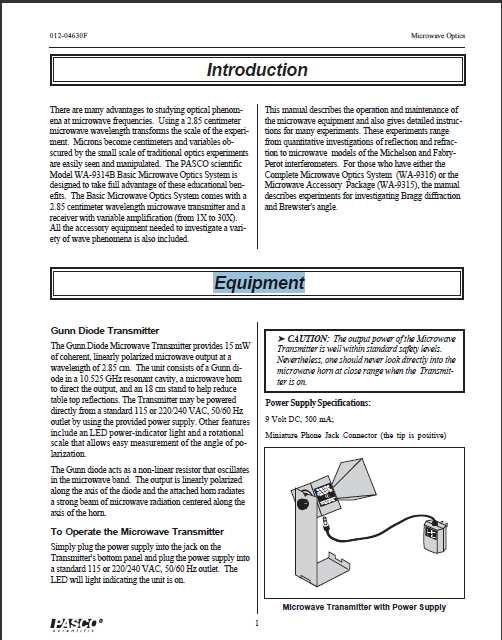
 MICROWAVE OPTICS Microwave Optics Introduction There are many advantages to studying optical phenomena at microwave frequencies. Using a 2.85 centimeter microwave wavelength transforms the scale of the
MICROWAVE OPTICS. Instruction Manual and Experiment Guide for the PASCO scientific Model WA-9314B F 4/ PASCO scientific $10.
 Includes Teacher's Notes and Typical Experiment Results Instruction Manual and Experiment Guide for the PASCO scientific Model WA-9314B 012-04630F 4/99 MICROWAVE OPTICS 1991 PASCO scientific $10.00 012-04630F
1 Diffraction of Microwaves
 1 Diffraction of Microwaves 1.1 Purpose In this lab you will investigate the coherent scattering of electromagnetic waves from a periodic structure. The experiment is a direct analog of the Bragg diffraction
Microwave Diffraction and Interference
 Microwave Diffraction and Interference Department of Physics Ryerson University rev.2014 1 Introduction The object of this experiment is to observe interference and diffraction of microwave radiation,
Experimental Competition
 37 th International Physics Olympiad Singapore 8 17 July 2006 Experimental Competition Wed 12 July 2006 Experimental Competition Page 2 List of apparatus and materials Label Component Quantity Label Component
Lloyd s Mirror. Understand the nature of sound-waves. Calculate the frequency of ultrasonic sound-waves by Lloyd s Mirror Interference.
 Lloyd s Mirror 1 Objective Understand the nature of sound-waves. Calculate the frequency of ultrasonic sound-waves by Lloyd s Mirror Interference. 2 Prelab Questions 1. What is meant by an ultrasonic sound-wave
Single-Slit Diffraction. = m, (Eq. 1)
") Single-Slit Diffraction Experimental Objectives To observe the interference pattern formed by monochromatic light passing through a single slit. Compare the diffraction patterns of a single-slit and a
Single-Slit Diffraction Experimental Objectives To observe the interference pattern formed by monochromatic light passing through a single slit. Compare the diffraction patterns of a single-slit and a
A Level. A Level Physics. WAVES: Combining Waves (Answers) AQA. Name: Total Marks: /30
 AQA. Name: Total Marks: /30") Visit http://www.mathsmadeeasy.co.uk/ for more fantastic resources. AQA A Level A Level Physics WAVES: Combining Waves (Answers) Name: Total Marks: /30 Maths Made Easy Complete Tuition Ltd 2017 1. To produce
Visit http://www.mathsmadeeasy.co.uk/ for more fantastic resources. AQA A Level A Level Physics WAVES: Combining Waves (Answers) Name: Total Marks: /30 Maths Made Easy Complete Tuition Ltd 2017 1. To produce
A Level. A Level Physics. WAVES: Combining Waves (Answers) OCR. Name: Total Marks: /30
 OCR. Name: Total Marks: /30") Visit http://www.mathsmadeeasy.co.uk/ for more fantastic resources. OCR A Level A Level Physics WAVES: Combining Waves (Answers) Name: Total Marks: /30 Maths Made Easy Complete Tuition Ltd 2017 1. To produce
Visit http://www.mathsmadeeasy.co.uk/ for more fantastic resources. OCR A Level A Level Physics WAVES: Combining Waves (Answers) Name: Total Marks: /30 Maths Made Easy Complete Tuition Ltd 2017 1. To produce
Lab 10 - Microwave and Light Interference
 Lab 10 Microwave and Light Interference L10-1 Name Date Partners Lab 10 - Microwave and Light Interference Amazing pictures of the microwave radiation from the universe have helped us determine the universe
Lab in a Box Microwave Interferometer
 In 1887 Michelson and Morley used an optical interferometer (a device invented by Michelson to accurately detect aether flow) to try and detect the relative motion of light through the luminous either.
Physics B Waves and Sound Name: AP Review. Show your work:
 Physics B Waves and Sound Name: AP Review Mechanical Wave A disturbance that propagates through a medium with little or no net displacement of the particles of the medium. Parts of a Wave Crest: high point
College Physics II Lab 3: Microwave Optics
 ACTIVITY 1: RESONANT CAVITY College Physics II Lab 3: Microwave Optics Taner Edis with Peter Rolnick Spring 2018 We will be dealing with microwaves, a kind of electromagnetic radiation with wavelengths
9. Microwaves. 9.1 Introduction. Safety consideration
 MW 9. Microwaves 9.1 Introduction Electromagnetic waves with wavelengths of the order of 1 mm to 1 m, or equivalently, with frequencies from 0.3 GHz to 0.3 THz, are commonly known as microwaves, sometimes
Experiment 1: Fraunhofer Diffraction of Light by a Single Slit
 Experiment 1: Fraunhofer Diffraction of Light by a Single Slit Purpose 1. To understand the theory of Fraunhofer diffraction of light at a single slit and at a circular aperture; 2. To learn how to measure
INTERFERENCE OF SOUND WAVES
 01/02 Interference - 1 INTERFERENCE OF SOUND WAVES The objectives of this experiment are: To measure the wavelength, frequency, and propagation speed of ultrasonic sound waves. To observe interference
Experiment 12: Microwaves
 MASSACHUSETTS INSTITUTE OF TECHNOLOGY Department of Physics 8.02 Spring 2005 OBJECTIVES Experiment 12: Microwaves To observe the polarization and angular dependence of radiation from a microwave generator
28 The diagram shows an experiment which has been set up to demonstrate two-source interference, using microwaves of wavelength λ.
 PhysicsndMathsTutor.com 28 The diagram shows an experiment which has been set up to demonstrate two-source interference, using microwaves of wavelength λ. 9702/1/M/J/02 X microwave transmitter S 1 S 2
Lab 10 - MICROWAVE AND LIGHT INTERFERENCE
 179 Name Date Partners Lab 10 - MICROWAVE AND LIGHT INTERFERENCE Amazing pictures of the microwave radiation from the universe have helped us determine the universe is 13.7 billion years old. This picture
Single Slit Diffraction
 PC1142 Physics II Single Slit Diffraction 1 Objectives Investigate the single-slit diffraction pattern produced by monochromatic laser light. Determine the wavelength of the laser light from measurements
Lab 10 - MICROWAVE AND LIGHT INTERFERENCE
 181 Name Date Partners Lab 10 - MICROWAVE AND LIGHT INTERFERENCE Amazing pictures of the microwave radiation from the universe have helped us determine the universe is 13.7 billion years old. This picture
Physics 4C Chabot College Scott Hildreth
 Physics 4C Chabot College Scott Hildreth The Inverse Square Law for Light Intensity vs. Distance Using Microwaves Experiment Goals: Experimentally test the inverse square law for light using Microwaves.
point at zero displacement string 80 scale / cm Fig. 4.1
 1 (a) Fig. 4.1 shows a section of a uniform string under tension at one instant of time. A progressive wave of wavelength 80 cm is moving along the string from left to right. At the instant shown, the
6 Experiment II: Law of Reflection
 Lab 6: Microwaves 3 Suggested Reading Refer to the relevant chapters, 1 Introduction Refer to Appendix D for photos of the apparatus This lab allows you to test the laws of reflection, refraction and diffraction
Standing waves in the microwave range
 Related topics Microwaves, electromagnetic waves, reflection, inverse square law Principle If electromagnetic waves are reflected to and fro between two reflectors, a standing wave results. The wavelength
Light and electromagnetic waves teaching in engineering education
 Light and electromagnetic waves teaching in engineering education Roman Ya. Kezerashvili The Graduate School and University Center, The City University of New York, New York, NY, USA E-mail: rkezerashvili@citytech.cuny.edu
7. Experiment K: Wave Propagation
 7. Experiment K: Wave Propagation This laboratory will be based upon observing standing waves in three different ways, through coaxial cables, in free space and in a waveguide. You will also observe some
ABC Math Student Copy
 Page 1 of 17 Physics Week 9(Sem. 2) Name Chapter Summary Waves and Sound Cont d 2 Principle of Linear Superposition Sound is a pressure wave. Often two or more sound waves are present at the same place
FRAUNHOFER AND FRESNEL DIFFRACTION IN ONE DIMENSION
 FRAUNHOFER AND FRESNEL DIFFRACTION IN ONE DIMENSION Revised November 15, 2017 INTRODUCTION The simplest and most commonly described examples of diffraction and interference from two-dimensional apertures
PC1141 Physics I. Speed of Sound. Traveling waves of speed v, frequency f and wavelength λ are described by
 PC1141 Physics I Speed of Sound 1 Objectives Determination of several frequencies of the signal generator at which resonance occur in the closed and open resonance tube respectively. Determination of the
LOS 1 LASER OPTICS SET
 LOS 1 LASER OPTICS SET Contents 1 Introduction 3 2 Light interference 5 2.1 Light interference on a thin glass plate 6 2.2 Michelson s interferometer 7 3 Light diffraction 13 3.1 Light diffraction on a
AS Physics Unit 5 - Waves 1
 AS Physics Unit 5 - Waves 1 WHAT IS WAVE MOTION? The wave motion is a means of transferring energy from one point to another without the transfer of any matter between the points. Waves may be classified
Polarization Experiments Using Jones Calculus
 Polarization Experiments Using Jones Calculus Reference http://chaos.swarthmore.edu/courses/physics50_2008/p50_optics/04_polariz_matrices.pdf Theory In Jones calculus, the polarization state of light is
Name: Lab Partner: Section:
 Chapter 11 Wave Phenomena Name: Lab Partner: Section: 11.1 Purpose Wave phenomena using sound waves will be explored in this experiment. Standing waves and beats will be examined. The speed of sound will
1 (a) State two properties which distinguish electromagnetic waves from other transverse waves [2] lamp eye
![1 (a) State two properties which distinguish electromagnetic waves from other transverse waves [2] lamp eye](/thumbs/88/115297818.jpg "1 (a) State two properties which distinguish electromagnetic waves from other transverse waves [2] lamp eye") 1 (a) State two properties which distinguish electromagnetic waves from other transverse waves............. [2] (b) (i) Describe what is meant by a plane polarised wave.... [2] (ii) Light from a filament
1 (a) State two properties which distinguish electromagnetic waves from other transverse waves............. [2] (b) (i) Describe what is meant by a plane polarised wave.... [2] (ii) Light from a filament
Conservation of energy during the reflection and transmission of microwaves
 Related topics Microwaves, electromagnetic waves, reflection, transmission, polarisation, conservation of energy, conservation laws Principle When electromagnetic waves impinge on an obstacle, reflection,
Interference and Diffraction of Microwaves
 Interference and Diffraction of Microwaves References: Equipment: Ford, Kenneth W., Classical and Modern Physics Vol2 Xerox College Publishing 1972 pp. 850-871. Pasco Instruction Manual and Experiment
KULLIYYAH OF ENGINEERING
 KULLIYYAH OF ENGINEERING DEPARTMENT OF ELECTRICAL & COMPUTER ENGINEERING ANTENNA AND WAVE PROPAGATION LABORATORY (ECE 4103) EXPERIMENT NO 3 RADIATION PATTERN AND GAIN CHARACTERISTICS OF THE DISH (PARABOLIC)
MICROWAVE AND RADAR LAB (EE-322-F) LAB MANUAL VI SEMESTER
 LAB MANUAL VI SEMESTER") 1 MICROWAVE AND RADAR LAB (EE-322-F) MICROWAVE AND RADAR LAB (EE-322-F) LAB MANUAL VI SEMESTER RAO PAHALD SINGH GROUP OF INSTITUTIONS BALANA(MOHINDERGARH)123029 Department Of Electronics and Communication
1 MICROWAVE AND RADAR LAB (EE-322-F) MICROWAVE AND RADAR LAB (EE-322-F) LAB MANUAL VI SEMESTER RAO PAHALD SINGH GROUP OF INSTITUTIONS BALANA(MOHINDERGARH)123029 Department Of Electronics and Communication
Interference & Superposition. Creating Complex Wave Forms
 Interference & Superposition Creating Complex Wave Forms Waves & Interference I. Definitions and Types II. Parameters and Equations III. Sound IV. Graphs of Waves V. Interference - superposition - standing
Introduction 1. The Experimental Method
 8.02 Fall 2001 A Microwave Generator, Receiver, and Reflector 1 Introduction 1 Hertz first generated electromagnetic waves in 1888, and we replicate Hertz s original experiment here. The method he used
... frequency, f speed, v......
 PhysicsAndMathsTutor.com 1 1. Define the terms wavelength, frequency and speed used to describe a progressive wave. wavelength, λ... frequency, f... speed, v... Hence derive the wave equation v = fλ which
EE 3324 Electromagnetics Laboratory
 EE 3324 Electromagnetics Laboratory Experiment #11 Microwave Systems 1. Objective The objective of Experiment #11 is to investigate microwave systems and associated measurement techniques. A precision
Q1. The figure below shows two ways in which a wave can travel along a slinky spring.
 PhysicsAndMathsTutor.com 1 Q1. The figure below shows two ways in which a wave can travel along a slinky spring. (a) State and explain which wave is longitudinal..... On the figure above, (i) clearly indicate
M1.D [1] M2.C [1] Suitable experiment eg diffraction through a door / out of a pipe
![M1.D [1] M2.C [1] Suitable experiment eg diffraction through a door / out of a pipe](/thumbs/78/77338681.jpg "M1.D [1] M2.C [1] Suitable experiment eg diffraction through a door / out of a pipe") M.D [] M.C [] M3.(a) Suitable experiment eg diffraction through a door / out of a pipe (b) Using c = d / t t = 500 / 480 = 5. s (c) (Measured time is difference between time taken by light and time taken
M.D [] M.C [] M3.(a) Suitable experiment eg diffraction through a door / out of a pipe (b) Using c = d / t t = 500 / 480 = 5. s (c) (Measured time is difference between time taken by light and time taken
(i) node [1] (ii) antinode...
![(i) node [1] (ii) antinode...](/thumbs/96/126586647.jpg "(i) node [1] (ii) antinode...") 1 (a) When used to describe stationary (standing) waves explain the terms node...... [1] (ii) antinode....... [1] (b) Fig. 5.1 shows a string fixed at one end under tension. The frequency of the mechanical
1 (a) When used to describe stationary (standing) waves explain the terms node...... [1] (ii) antinode....... [1] (b) Fig. 5.1 shows a string fixed at one end under tension. The frequency of the mechanical
SECTION A Waves and Sound
 AP Physics Multiple Choice Practice Waves and Optics SECTION A Waves and Sound 1. Which of the following statements about the speed of waves on a string are true? I. The speed depends on the tension in
Chapter Ray and Wave Optics
 109 Chapter Ray and Wave Optics 1. An astronomical telescope has a large aperture to [2002] reduce spherical aberration have high resolution increase span of observation have low dispersion. 2. If two
Experiment: P34 Resonance Modes 1 Resonance Modes of a Stretched String (Power Amplifier, Voltage Sensor)
") PASCO scientific Vol. 2 Physics Lab Manual: P34-1 Experiment: P34 Resonance Modes 1 Resonance Modes of a Stretched String (Power Amplifier, Voltage Sensor) Concept Time SW Interface Macintosh file Windows
PASCO scientific Vol. 2 Physics Lab Manual: P34-1 Experiment: P34 Resonance Modes 1 Resonance Modes of a Stretched String (Power Amplifier, Voltage Sensor) Concept Time SW Interface Macintosh file Windows
Physics. Light Waves & Physical Optics
 Physics Light Waves & Physical Optics Physical Optics Physical optics or wave optics, involves the effects of light waves that are not related to the geometric ray optics covered previously. We will use
Experiment 5: Spark Gap Microwave Generator Dipole Radiation, Polarization, Interference W14D2
 Experiment 5: Spark Gap Microwave Generator Dipole Radiation, Polarization, Interference W14D2 1 Announcements Week 14 Prepset due Fri at 8:30 am PS 11 due Week 14 Friday at 9 pm in boxes outside 26-152
SECTION A Waves and Sound
 AP Physics Multiple Choice Practice Waves and Optics SECTION A Waves and Sound 2. A string is firmly attached at both ends. When a frequency of 60 Hz is applied, the string vibrates in the standing wave
Single, Double And N-Slit Diffraction. B.Tech I
 Single, Double And N-Slit Diffraction B.Tech I Diffraction by a Single Slit or Disk If light is a wave, it will diffract around a single slit or obstacle. Diffraction by a Single Slit or Disk The resulting
Waves Review Checklist Pulses 5.1.1A Explain the relationship between the period of a pendulum and the factors involved in building one
 5.1.1 Oscillating Systems Waves Review hecklist 5.1.2 Pulses 5.1.1A Explain the relationship between the period of a pendulum and the factors involved in building one Four pendulums are built as shown
ABC Math Student Copy. N. May ABC Math Student Copy. Physics Week 13(Sem. 2) Name. Light Chapter Summary Cont d 2
 Name. Light Chapter Summary Cont d 2") Page 1 of 12 Physics Week 13(Sem. 2) Name Light Chapter Summary Cont d 2 Lens Abberation Lenses can have two types of abberation, spherical and chromic. Abberation occurs when the rays forming an image
Page 1 of 12 Physics Week 13(Sem. 2) Name Light Chapter Summary Cont d 2 Lens Abberation Lenses can have two types of abberation, spherical and chromic. Abberation occurs when the rays forming an image
Q1. (Total 1 mark) Q2. cannot (Total 1 mark)
 Q2. cannot (Total 1 mark)") Q1.Two points on a progressive wave are one-eighth of a wavelength apart. The distance between them is 0.5 m, and the frequency of the oscillation is 10 Hz. What is the minimum speed of the wave? 0.2 m
Q1.Two points on a progressive wave are one-eighth of a wavelength apart. The distance between them is 0.5 m, and the frequency of the oscillation is 10 Hz. What is the minimum speed of the wave? 0.2 m
Chapter 23 Electromagnetic Waves Lecture 14
 Chapter 23 Electromagnetic Waves Lecture 14 23.1 The Discovery of Electromagnetic Waves 23.2 Properties of Electromagnetic Waves 23.3 Electromagnetic Waves Carry Energy and Momentum 23.4 Types of Electromagnetic
Experiment 10. Diffraction and interference of light
 Experiment 10. Diffraction and interference of light 1. Purpose Perform single slit and Young s double slit experiment by using Laser and computer interface in order to understand diffraction and interference
PHYS 3153 Methods of Experimental Physics II O2. Applications of Interferometry
 Purpose PHYS 3153 Methods of Experimental Physics II O2. Applications of Interferometry In this experiment, you will study the principles and applications of interferometry. Equipment and components PASCO
Radiation characteristics of a dipole antenna in free space
 Department of Electrical and Electronic Engineering (EEE), Bangladesh University of Engineering and Technology (BUET). EEE 434: Microwave Engineering Laboratory Experiment No.: A1 Radiation characteristics
(A) 2f (B) 2 f (C) f ( D) 2 (E) 2
 2f (B) 2 f (C) f ( D) 2 (E) 2") 1. A small vibrating object S moves across the surface of a ripple tank producing the wave fronts shown above. The wave fronts move with speed v. The object is traveling in what direction and with what
1. A small vibrating object S moves across the surface of a ripple tank producing the wave fronts shown above. The wave fronts move with speed v. The object is traveling in what direction and with what
Study of Standing Waves to Find Speed of Sound in Air
 Study of Standing Waves to Find Speed of Sound in Air Purpose Using mobile devices as sound analyzer and sound generator to study standing waves and determine the speed of sound in air. Theory The velocity
3B SCIENTIFIC PHYSICS
 3B SCIENTIFIC PHYSICS Equipment Set for Wave Optics with Laser U17303 Instruction sheet 10/08 Alf 1. Safety instructions The laser emits visible radiation at a wavelength of 635 nm with a maximum power
Physics 2310 Lab #2 Speed of Sound & Resonance in Air
 Physics 2310 Lab #2 Speed of Sound & Resonance in Air Objective: The objectives of this experiment are a) to measure the speed of sound in air, and b) investigate resonance within air. Apparatus: Pasco
PHYS102 Previous Exam Problems. Sound Waves. If the speed of sound in air is not given in the problem, take it as 343 m/s.
 PHYS102 Previous Exam Problems CHAPTER 17 Sound Waves Sound waves Interference of sound waves Intensity & level Resonance in tubes Doppler effect If the speed of sound in air is not given in the problem,
Chapter 3. Experiment 1: Sound. 3.1 Introduction
 Chapter 3 Experiment 1: Sound 3.1 Introduction Sound is classified under the topic of mechanical waves. A mechanical wave is a term which refers to a displacement of elements in a medium from their equilibrium
OSCILLATIONS and WAVES
 OSCILLATIONS and WAVES Oscillations Oscillations are vibrations which repeat themselves. EXAMPLE: Oscillations can be driven externally, like a pendulum in a gravitational field EXAMPLE: Oscillations can
Vibrations on a String and Resonance
 Vibrations on a String and Resonance Umer Hassan and Muhammad Sabieh Anwar LUMS School of Science and Engineering September 7, 2010 How does our radio tune into different channels? Can a music maestro
Demonstrate understanding of wave systems. Demonstrate understanding of wave systems. Achievement Achievement with Merit Achievement with Excellence
 Demonstrate understanding of wave systems Subject Reference Physics 3.3 Title Demonstrate understanding of wave systems Level 3 Credits 4 Assessment External This achievement standard involves demonstrating
Physics 248 Spring 2009 Lab 1: Interference and Diffraction
 Name Section Physics 248 Spring 2009 Lab 1: Interference and Diffraction Your TA will use this sheet to score your lab. It is to be turned in at the end of lab. You must clearly explain your reasoning
MICROWAVE OPTICS. ly-wtf* Instruction Manual and Experiment Guide for. the PASCO scientific. Model WA-9314B
 Includes Teacher's Notes and Typical Experiment Results P^ Instruction Manual and Experiment Guide for the PASCO scientific Model WA-9314B 0I2-04630G MICROWAVE OPTICS ly-wtf* (g) 10101 Foothills Blvd.
EC ANTENNA AND WAVE PROPAGATION
 EC6602 - ANTENNA AND WAVE PROPAGATION FUNDAMENTALS PART-B QUESTION BANK UNIT 1 1. Define the following parameters w.r.t antenna: i. Radiation resistance. ii. Beam area. iii. Radiation intensity. iv. Directivity.
Physical Optics. Diffraction.
 Physical Optics. Diffraction. Interference Young s interference experiment Thin films Coherence and incoherence Michelson interferometer Wave-like characteristics of light Huygens-Fresnel principle Interference.
Electricity. Interference of microwaves Electromagnetic Oscillations and Waves. What you need:
 Electromagnetic Oscillations and Waves Electricity What you can learn about Wavelength Standing wave Reflection Transmission Michelson interferometer Principle: A microwave beam, after reflection from
Diffraction and Interference of Water Waves
 Diffraction and Interference of Water Waves Diffraction of Waves Diffraction the bending and spreading of a wave when it passes through an opening or around an obstacle Examples: sound waves travel through
Standing Waves and Voltage Standing Wave Ratio (VSWR)
") Exercise 3-1 Standing Waves and Voltage Standing Wave Ratio (VSWR) EXERCISE OBJECTIVES Upon completion of this exercise, you will know how standing waves are created on transmission lines. You will be
Exercise 3-1 Standing Waves and Voltage Standing Wave Ratio (VSWR) EXERCISE OBJECTIVES Upon completion of this exercise, you will know how standing waves are created on transmission lines. You will be
Activity P35: Light Intensity in Double-Slit and Single-Slit Diffraction Patterns (Light Sensor, Rotary Motion Sensor)
") Name Class Date Activity P35: Light Intensity in Double-Slit and Single-Slit Diffraction Patterns (Light Sensor, Rotary Motion Sensor) Concept DataStudio ScienceWorkshop (Mac) ScienceWorkshop (Win) Interference
Name Class Date Activity P35: Light Intensity in Double-Slit and Single-Slit Diffraction Patterns (Light Sensor, Rotary Motion Sensor) Concept DataStudio ScienceWorkshop (Mac) ScienceWorkshop (Win) Interference
Useful general references for this experiment are Cheng [1], and Ramo et al [2].
![Useful general references for this experiment are Cheng [1], and Ramo et al [2].](/thumbs/74/70212276.jpg "Useful general references for this experiment are Cheng [1], and Ramo et al [2].") Experiment 7. Wave Propagation Updated RWH 21 August 2012 1 Aim In this experiment you will measure the radiation pattern of a half-wave dipole antenna, determine the resonant frequencies of a microwave
Experiment 7. Wave Propagation Updated RWH 21 August 2012 1 Aim In this experiment you will measure the radiation pattern of a half-wave dipole antenna, determine the resonant frequencies of a microwave
Fig On Fig. 6.1 label one set of the lines in the first order spectrum R, G and V to indicate which is red, green and violet.
 1 This question is about the light from low energy compact fluorescent lamps which are replacing filament lamps in the home. (a) The light from a compact fluorescent lamp is analysed by passing it through
3B SCIENTIFIC PHYSICS
 3B SCIENTIFIC PHYSICS Equipment Set for Wave Optics with Laser 1003053 Instruction sheet 06/18 Alf 1. Safety instructions The laser emits visible radiation at a wavelength of 635 nm with a maximum power
Spectroscopy Lab 2. Reading Your text books. Look under spectra, spectrometer, diffraction.
 1 Spectroscopy Lab 2 Reading Your text books. Look under spectra, spectrometer, diffraction. Consult Sargent Welch Spectrum Charts on wall of lab. Note that only the most prominent wavelengths are displayed
Waves & Energy Transfer. Introduction to Waves. Waves are all about Periodic Motion. Physics 11. Chapter 11 ( 11-1, 11-7, 11-8)
") Waves & Energy Transfer Physics 11 Introduction to Waves Chapter 11 ( 11-1, 11-7, 11-8) Waves are all about Periodic Motion. Periodic motion is motion that repeats after a certain period of time. This
Waves & Energy Transfer Physics 11 Introduction to Waves Chapter 11 ( 11-1, 11-7, 11-8) Waves are all about Periodic Motion. Periodic motion is motion that repeats after a certain period of time. This
Electromagnetic Induction - A
 Electromagnetic Induction - A APPARATUS 1. Two 225-turn coils 2. Table Galvanometer 3. Rheostat 4. Iron and aluminum rods 5. Large circular loop mounted on board 6. AC ammeter 7. Variac 8. Search coil
b) (4) If you could look at a snapshot of the waves, how far apart in space are two successive positive peaks of the electric field?
 (4) If you could look at a snapshot of the waves, how far apart in space are two successive positive peaks of the electric field?") General Physics II Exam 3 - Chs. 22 25 - EM Waves & Optics October 20, 206 Name Rec. Instr. Rec. Time For full credit, make your work clear. Show formulas used, essential steps, and results with correct
General Physics II Exam 3 - Chs. 22 25 - EM Waves & Optics October 20, 206 Name Rec. Instr. Rec. Time For full credit, make your work clear. Show formulas used, essential steps, and results with correct
Chapter Wave Optics. MockTime.com. Ans: (d)
") Chapter Wave Optics Q1. Which one of the following phenomena is not explained by Huygen s construction of wave front? [1988] (a) Refraction Reflection Diffraction Origin of spectra Q2. Which of the following
Chapter Wave Optics Q1. Which one of the following phenomena is not explained by Huygen s construction of wave front? [1988] (a) Refraction Reflection Diffraction Origin of spectra Q2. Which of the following
EDUCATIONAL SPECTROPHOTOMETER ACCESSORY KIT AND EDUCATIONAL SPECTROPHOTOMETER SYSTEM
 GAIN 1 10 100 Instruction Manual and Experiment Guide for the PASCO scientific Model OS-8537 and OS-8539 012-06575A 3/98 EDUCATIONAL SPECTROPHOTOMETER ACCESSORY KIT AND EDUCATIONAL SPECTROPHOTOMETER SYSTEM
Lecture 2: Interference
 Lecture 2: Interference λ S 1 d S 2 Lecture 2, p.1 Today Interference of sound waves Two-slit interference Lecture 2, p.2 Review: Wave Summary ( ) ( ) The formula y x,t = Acoskx ωt describes a harmonic
A progressive wave of frequency 150 Hz travels along a stretched string at a speed of 30 m s 1.
 1. progressive wave of frequency 150 Hz travels along a stretched string at a speed of 30 m s 1. What is the phase difference between two points that are 50 mm apart on the string? zero 90 180 360 2 Which
AP PHYSICS WAVE BEHAVIOR
 AP PHYSICS WAVE BEHAVIOR NAME: HB: ACTIVITY I. BOUNDARY BEHAVIOR As a wave travels through a medium, it will often reach the end of the medium and encounter an obstacle or perhaps another medium through
Section A Conceptual and application type questions. 1 Which is more observable diffraction of light or sound? Justify. (1)
") INDIAN SCHOOL MUSCAT Department of Physics Class : XII Physics Worksheet - 6 (2017-2018) Chapter 9 and 10 : Ray Optics and wave Optics Section A Conceptual and application type questions 1 Which is more
INDIAN SCHOOL MUSCAT Department of Physics Class : XII Physics Worksheet - 6 (2017-2018) Chapter 9 and 10 : Ray Optics and wave Optics Section A Conceptual and application type questions 1 Which is more
Chapter 34 The Wave Nature of Light; Interference. Copyright 2009 Pearson Education, Inc.
 Chapter 34 The Wave Nature of Light; Interference 34-7 Luminous Intensity The intensity of light as perceived depends not only on the actual intensity but also on the sensitivity of the eye at different
Exercise 1-3. Radar Antennas EXERCISE OBJECTIVE DISCUSSION OUTLINE DISCUSSION OF FUNDAMENTALS. Antenna types
 Exercise 1-3 Radar Antennas EXERCISE OBJECTIVE When you have completed this exercise, you will be familiar with the role of the antenna in a radar system. You will also be familiar with the intrinsic characteristics
PERFORMANCE STUDIES OF RADIAL LINE SLOT ARRAY (RLSA) ANTENNA AT 5.8 GHz ON DIFFERENT MATERIALS Omar Abdul Aziz Tharek Abdul Rahman
 ANTENNA AT 5.8 GHz ON DIFFERENT MATERIALS Omar Abdul Aziz Tharek Abdul Rahman") 102 Recent Developments in Small Size Antenna 9 PERFORMANCE STUDIES OF RADIAL LINE SLOT ARRAY (RLSA) ANTENNA AT 5.8 GHz ON DIFFERENT MATERIALS Omar Abdul Aziz Tharek Abdul Rahman 9.1 INTRODUCTION The type
102 Recent Developments in Small Size Antenna 9 PERFORMANCE STUDIES OF RADIAL LINE SLOT ARRAY (RLSA) ANTENNA AT 5.8 GHz ON DIFFERENT MATERIALS Omar Abdul Aziz Tharek Abdul Rahman 9.1 INTRODUCTION The type
PANalytical X pert Pro Gazing Incidence X-ray Reflectivity User Manual (Version: )
") University of Minnesota College of Science and Engineering Characterization Facility PANalytical X pert Pro Gazing Incidence X-ray Reflectivity User Manual (Version: 2012.10.17) The following instructions
University of Minnesota College of Science and Engineering Characterization Facility PANalytical X pert Pro Gazing Incidence X-ray Reflectivity User Manual (Version: 2012.10.17) The following instructions