Behzad Razavi, RF Microelectronics, Prentice Hall PTR, 1998
|
|
|
- Jade Miller
- 5 years ago
- Views:
Transcription
1 2008/Sep/17 1
2 Text Book: Behzad Razavi, RF Microelectronics, Prentice Hall PTR, 1998 References: (MSR) Thomas H. Lee, The Design of CMOS Radio-Frequency Integrated Circuits, 2/e, Cambridge University Press, Contents: (Oscillators) (PA) 3. IC (LNA) (Mixer) 2
3 Homework: % A4 80% : 35% : 35% : 20% ycchiang1970@nchu.edu.tw : : : (Lab. 717) 3
4 Introduction What is Radio Frequency? Frequency (Hz) Long wave radio AM broadcast radio Shortwave radio VHF TV FM broadcast radio Microwaves Far Infrared Infrared Visible light Traditional definition: Wavelength (m) Frequency range for radio and television transmission (1MHz 1GHz) 4
5 Band Name & Abbr. Frequency & λ Introduction Example Uses Very Low Frequency Low Frequency Medium Frequency High Frequency Very High Frequency Ultra High Frequency Super High Frequency Extremely High Frequency 3 30 khz 0 km km khz km 1 km khz 1 km 0 m 3 30 MHz 0 m m MHz m 1 m MHz 1 m 0 mm 3 30 GHz 0 mm mm GHz mm 1 mm Submarine communication, avalanche beacons, wireless heart rate monitors Navigation, time signals, AM longwave broadcasting AM (Medium-wave) broadcasts Shortwave broadcasts and amateur radio FM and television broadcasts television broadcasts, mobile phones, wireless LAN, ground-to-air and air-to-air communications microwave devices, mobile phones (W-CDMA), WLAN, most modern Radars Radio astronomy, high-speed microwave radio relay 5
6 6 Introduction Standard Prefixes da deka h hecto k kilo M mega G giga T tera Factor Abbreviation Prefix a atto f femto p pico n nano micro m milli c centi d deci Factor Abbreviation Prefix µ
7 Introduction IC high integration trend: (Circuit Area) Die Cost = (Process (Wafer Area) Cost) E.g. A device area = 30 µ m 30 µ m 8 - inch wafer area 0.1m 0.1m π Process cost = Device cost One rule for IC design NT$ NT$ Cost of on - chip devices << Cost of # of on - chip devices Cost of customers and Use fewest off-chip devices as you can # of off off - chip - chip devices devices 7
8 IC production schedule Introduction Design phase: 2 months Layout phase: 0.5~1 month Process phase: 0.5~2 months Shipping & package phase: 0.2~0.5 month Measurement: 1 months Total duration: 4.2~6.5 months Since the IC production cycle time is very long and the time to market is very tight, the design iteration should be minimized. One iteration for digital ICs, 1~2 iteration for analog/rf ICs. 8
9 Introduction How to minimize design iteration? For Foundry Offer accurate device models Active devices: corner models, Monte Carlo models Passive devices: variation ranges For Designer Current-biased scheme for analog/rf ICs Simulate circuits with most conditions (worst-case simulation) Add design margin to overcome process variations Better circuit architectures to overcome process variations 9
10 Introduction RF designer Maxwell s Equations AC / Field analysis / time domain dbm / s-parameters / dbc Smith Chart Noise Figure in db Thermal / Flicker / Shot Noise GaAs / BiCMOS / CMOS 20-transistors ICs (for one block) Network & Spectrum analyzer Cadence SpectreRF Mentor EldoRF Agilent ADS / RFDE L Digital/Analog designer Ohm s law DC / AC Volts SPICE Noise in nv/sqrt(hz) Thermal Noise CMOS 20-transistor bias circuits Oscilloscope espice hspice L
 FM transmitter, (b) FM receiver Figure 1.")
11 Introduction Figure 1.1 (a) FM transmitter, (b) FM receiver Figure 1.2 RF section of a cellphone [1] 11
12 Design Bottleneck RF and baseband processing in a transceiver RF Section Baseband Section Although the baseband section is more complex than RF section in terms of the number of devices, the RF section is still the design bottleneck of the entire system for 3 reasons: 1. Multidisciplinary Field 2. RF Design Hexagon 3. Design Tools 12
13 Multidisciplinary Field Design Bottleneck Microwave Theory Communication Theory Random Signals Signal Propagation RF Design Transceiver Architectures Multiple Access Wireless Standards CAD Tools IC Design 13
14 RF Design Hexagon Design Bottleneck Noise Power Linearity Frequency Supply Voltage Gain Design Tools Nonlinearity, time variance, and noise in RF circuits make the SPICElike tools (linear ac analysis) no longer suitable or efficient. External components cannot be modeled by typical devices in SPICE. They can usually be characterized only by S-parameters. 14
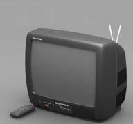
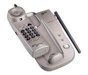
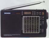

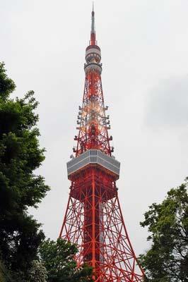
15 Applications 15
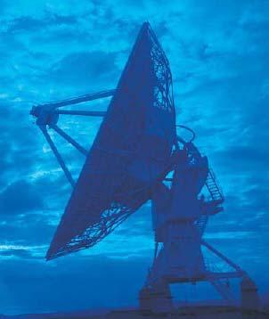
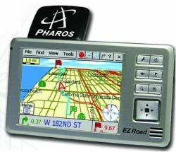
16 Applications 16
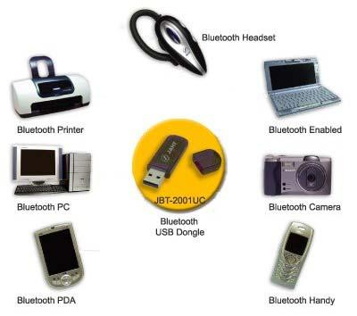
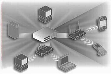
17 Applications 17


18 Applications 18
19 Analog and Digital Systems Voice Modulator Power Amplifier Carrier (a) Audio Amplifier Downconverter Demodulator Low-Noise Amplifier Carrier (b) Figure 1.6 Block diagram of a generic analog RF system: (a) transmitter, (b) receiver. 19
20 Analog and Digital Systems Digital Power Amplifier Voice ADC Voice Compression Coding Interleaving Pulse Shaping Modulator (a) Carrier Down Converter ADC Demodulator Equalizer Carrier Digital De-interleaving Decoding Audio Amplifier DAC Voice Decompression (b) Figure 1.7 Block diagram of a generic digital RF system: (a) transmitter, (b) receiver. 20
21 Analog and Digital Systems In the simplest case: the main consideration is the distance Power delivered and sensitivity of the receiver In a realistic environment: interference, multi-path, movement, etc. Signal processing will achieve a higher performance Which parts are RF electronics?
22 GaAs Choice of Technology Higher (breakdown voltage) x (higher cutoff frequency) product, semiinsulating substrate, and high-quality inductors and capacitor. Low-yield, low integration, high-cost PA s, front-end switches BiCMOS/ SiGe BiCMOS Moderate performance and integration, moderate cost CMOS High integration, low-cost Substrate coupling / loss, modeling, etc Silicon BJT SiGe HBT 22
22. VLSI in Communications
 22. VLSI in Communications State-of-the-art RF Design, Communications and DSP Algorithms Design VLSI Design Isolated goals results in: - higher implementation costs - long transition time between system
Technician License Course Chapter 2 Radio and Signals Fundamentals
 Technician License Course Chapter 2 Radio and Signals Fundamentals Handling Large and Small Numbers Electronics and Radio use a large range of sizes, i.e., 0.000000000001 to 1000000000000. Scientific Notation
Low Power RF Transceivers
 Low Power RF Transceivers Mr. Zohaib Latif 1, Dr. Amir Masood Khalid 2, Mr. Uzair Saeed 3 1,3 Faculty of Computing and Engineering, Riphah International University Faisalabad, Pakistan 2 Department of
PRINCIPLES OF COMMUNICATION SYSTEMS. Lecture 1- Introduction Elements, Modulation, Demodulation, Frequency Spectrum
 PRINCIPLES OF COMMUNICATION SYSTEMS Lecture 1- Introduction Elements, Modulation, Demodulation, Frequency Spectrum Topic covered Introduction to subject Elements of Communication system Modulation General
VLSI Chip Design Project TSEK01
 VLSI Chip Design Project TSEK01 Project description and requirement specification Version 1.0 Project: 250mW ISM Band Class D/E Power Amplifier Project number: 4 Project Group: Name Project members Telephone
Overview and Challenges
 RF/RF-SoC Overview and Challenges Fang Chen May 14, 2004 1 Content What is RF Research Topics in RF RF IC Design/Verification RF IC System Design Circuit Implementation What is RF-SoC Design Methodology
Session 3. CMOS RF IC Design Principles
 Session 3 CMOS RF IC Design Principles Session Delivered by: D. Varun 1 Session Topics Standards RF wireless communications Multi standard RF transceivers RF front end architectures Frequency down conversion
Technician Licensing Class
 Technician Licensing Class Go Picture Presented These! by Amateur Radio Technician Class Element 2 Course Presentation ELEMENT 2 SUB-ELEMENTS (Groupings) About Ham Radio Call Signs Control Mind the Rules
VLSI Chip Design Project TSEK06
 VLSI Chip Design Project TSEK06 Project Description and Requirement Specification Version 1.1 Project: 100 MHz, 10 dbm direct VCO modulating FM transmitter Project number: 4 Project Group: Name Project
TSEK03: Radio Frequency Integrated Circuits (RFIC) Lecture 1a: Course Introduction
 Lecture 1a: Course Introduction") TSEK03: Radio Frequency Integrated Circuits (RFIC) Lecture 1a: Course Introduction Ted Johansson, ISY ted.johansson@liu.se RFIC Main Objectives Advanced continuation of TSEK02 Radio Electronics Main focus
TSEK03: Radio Frequency Integrated Circuits (RFIC) Lecture 1a: Course Introduction Ted Johansson, ISY ted.johansson@liu.se RFIC Main Objectives Advanced continuation of TSEK02 Radio Electronics Main focus
COMM 704: Communication Systems
 COMM 704: Communication Lecture 1: Introduction Dr. Mohamed Abd El Ghany, Mohamed.abdel-ghany@guc.edu.eg Course Objective Give an introduction to the basic concepts of electronic communication systems
Overview: Trends and Implementation Challenges for Multi-Band/Wideband Communication
 Overview: Trends and Implementation Challenges for Multi-Band/Wideband Communication Mona Mostafa Hella Assistant Professor, ESCE Department Rensselaer Polytechnic Institute What is RFIC? Any integrated
An Inductor-Based 52-GHz 0.18 µm SiGe HBT Cascode LNA with 22 db Gain
 An Inductor-Based 52-GHz 0.18 µm SiGe HBT Cascode LNA with 22 db Gain Michael Gordon, Sorin P. Voinigescu University of Toronto Toronto, Ontario, Canada ESSCIRC 2004, Leuven, Belgium Outline Motivation
Antenna & Propagation. Basic Radio Wave Propagation
 For updated version, please click on http://ocw.ump.edu.my Antenna & Propagation Basic Radio Wave Propagation by Nor Hadzfizah Binti Mohd Radi Faculty of Electric & Electronics Engineering hadzfizah@ump.edu.my
TSEK03: Radio Frequency Integrated Circuits (RFIC) Lecture 1a: Introduction
 Lecture 1a: Introduction") TSEK03: Radio Frequency Integrated Circuits (RFIC) Lecture 1a: Introduction Ted Johansson, EKS, ISY ted.johansson@liu.se RFIC Main Objectives Advanced continuation of TSEK02 Radio Electronics Main focus
TSEK03: Radio Frequency Integrated Circuits (RFIC) Lecture 1a: Introduction Ted Johansson, EKS, ISY ted.johansson@liu.se RFIC Main Objectives Advanced continuation of TSEK02 Radio Electronics Main focus
RFIC Design ELEN 376 Session 1
 RFIC Design ELEN 376 Session 1 Instructor: Dr. Allen Sweet April 3, 2002 Copy right 2002, elen376 1 General Information Instructor: Dr. Allen Sweet Email: allensweet@aol.com Home work/project submissions:
RFIC Design ELEN 351 Lecture 1: General Discussion
 RFIC Design ELEN 351 Lecture 1: General Discussion Instructor: Dr. Allen Sweet Copy right 2003, ELEN351 1 General Information Instructor: Dr. Allen Sweet Email: allensweet@aol.com Home work/project submissions:
Designing a 960 MHz CMOS LNA and Mixer using ADS. EE 5390 RFIC Design Michelle Montoya Alfredo Perez. April 15, 2004
 Designing a 960 MHz CMOS LNA and Mixer using ADS EE 5390 RFIC Design Michelle Montoya Alfredo Perez April 15, 2004 The University of Texas at El Paso Dr Tim S. Yao ABSTRACT Two circuits satisfying the
Elements of Communication System Channel Fig: 1: Block Diagram of Communication System Terminology in Communication System
 Content:- Fundamentals of Communication Engineering : Elements of a Communication System, Need of modulation, electromagnetic spectrum and typical applications, Unit V (Communication terminologies in communication
Technical Article A DIRECT QUADRATURE MODULATOR IC FOR 0.9 TO 2.5 GHZ WIRELESS SYSTEMS
 Introduction As wireless system designs have moved from carrier frequencies at approximately 9 MHz to wider bandwidth applications like Personal Communication System (PCS) phones at 1.8 GHz and wireless
frequency (Hertz)(Hz)
(Hz)") Part C Part B Part A Shedding Light on Electromagnetic Waves Name: 1. Fill in the diagram. The Electromagnetic 10 4 10 5 10 6 10 7 10 8 10 9 10 10 10 11 10 12 10 13 10 14 10 15 10 16 10 17 10 18 10 19
Part C Part B Part A Shedding Light on Electromagnetic Waves Name: 1. Fill in the diagram. The Electromagnetic 10 4 10 5 10 6 10 7 10 8 10 9 10 10 10 11 10 12 10 13 10 14 10 15 10 16 10 17 10 18 10 19
A 5 GHz CMOS Low Power Down-conversion Mixer for Wireless LAN Applications
 Proceedings of the 5th WSEAS Int. Conf. on CIRCUITS, SYSTES, ELECTRONICS, CONTROL & SIGNAL PROCESSING, Dallas, USA, November 1-, 2006 26 A 5 GHz COS Low Power Down-conversion ixer for Wireless LAN Applications
What is a Communications System?
 Introduction to Communication Systems: An Overview James Flynn Sharlene Katz What is a Communications System? A communications system transfers an information bearing signal from a source to one or more
Satellite Tuner Single Chip Simulation with Advanced Design System
 Turning RF IC technology into successful design Satellite Tuner Single Chip Simulation with Advanced Design System Cédric Pujol - Central R&D March 2002 STMicroelectronics Outline ❽ STMicroelectronics
LOW COST PHASED ARRAY ANTENNA TRANSCEIVER FOR WPAN APPLICATIONS
 LOW COST PHASED ARRAY ANTENNA TRANSCEIVER FOR WPAN APPLICATIONS Introduction WPAN (Wireless Personal Area Network) transceivers are being designed to operate in the 60 GHz frequency band and will mainly
65-GHz Receiver in SiGe BiCMOS Using Monolithic Inductors and Transformers
 65-GHz Receiver in SiGe BiCMOS Using Monolithic Inductors and Transformers Michael Gordon, Terry Yao, Sorin P. Voinigescu University of Toronto March 10 2006, UBC, Vancouver Outline Motivation mm-wave
Technician Licensing Class T5
 Technician Licensing Class T5 Amateur Radio Course Monroe EMS Building Monroe, Utah January 11/18, 2014 January 22, 2014 Testing Session Valid dates: July 1, 2010 June 30, 2014 Amateur Radio Technician
Packaged mm-wave GaN, GaAs and Si ICs for 5G and automotive radar
 Packaged mm-wave GaN, GaAs and Si ICs for 5G and automotive radar Eric Leclerc UMS 1 st Nov 2018 Outline Why heterogenous integration? About UMS Technology portfolio Design tooling: Cadence / GoldenGate
EECS 142/242A Course Overview. Prof. Ali M. Niknejad University of California, Berkeley
 EECS 142/242A Course Overview Prof. Ali M. Niknejad University of California, Berkeley Course Logistics Instructor: Ali Niknejad (niknejad@berkeley.edu) Graduate Student Instructors: Nai-Chung Kuo and
mmw to THz ultra high data rate radio access technologies
 mmw to THz ultra high data rate radio access technologies Dr. Laurent HERAULT VP Europe, CEA LETI Pierre Vincent Head of RF IC design Lab, CEA LETI Outline mmw communication use cases and standards mmw
Amateur Wireless Station Operators License Exam
 Amateur Wireless Station Operators License Exam Study material 2017 South India Amateur Radio Society, Chennai CHAPTER 5 1 Chapter 5 Amateur Wireless Station Operators License Exam Study Material Chapter
Electrical Fundamentals and Basic Components Chapters T2, T3, G4
 Electrical Fundamentals and Basic Components Chapters T2, T3, G4 Some Basic Math, Electrical Fundamentals, AC Power, The Basics of Basic Components, A Little More Component Detail, Reactance and Impedance
ITRS: RF and Analog/Mixed- Signal Technologies for Wireless Communications. Nick Krajewski CMPE /16/2005
 ITRS: RF and Analog/Mixed- Signal Technologies for Wireless Communications Nick Krajewski CMPE 640 11/16/2005 Introduction 4 Working Groups within Wireless Analog and Mixed Signal (0.8 10 GHz) (Covered
Instrumentation Receiver: Analog Signal Processing for a DSP World. Rick Campbell Portland State University
 Instrumentation Receiver: Analog Signal Processing for a DSP World Rick Campbell Portland State University Tonight s Talk discusses 3 questions: What is an Instrumentation Receiver? How does Rick design
An Introduction to Electrical and Electronic Engineering Communication. Dr. Cahit Karakuş, 2018
 An Introduction to Electrical and Electronic Engineering Communication Dr. Cahit Karakuş, 2018 Significance of Human Communication Methods of communication: 1. Face to face 2. Signals 3. Written word (letters)
Fully integrated UHF RFID mobile reader with power amplifiers using System-in-Package (SiP)
") Fully integrated UHF RFID mobile reader with power amplifiers using System-in-Package (SiP) Hyemin Yang 1, Jongmoon Kim 2, Franklin Bien 3, and Jongsoo Lee 1a) 1 School of Information and Communications,
Fully integrated UHF RFID mobile reader with power amplifiers using System-in-Package (SiP) Hyemin Yang 1, Jongmoon Kim 2, Franklin Bien 3, and Jongsoo Lee 1a) 1 School of Information and Communications,
What to do with THz? Ali M. Niknejad Berkeley Wireless Research Center University of California Berkeley. WCA Futures SIG
 What to do with THz? Ali M. Niknejad Berkeley Wireless Research Center University of California Berkeley WCA Futures SIG Outline THz Overview Potential THz Applications THz Transceivers in Silicon? Application
High-Linearity CMOS. RF Front-End Circuits
 High-Linearity CMOS RF Front-End Circuits Yongwang Ding Ramesh Harjani iigh-linearity CMOS tf Front-End Circuits - Springer Library of Congress Cataloging-in-Publication Data A C.I.P. Catalogue record
The New England Radio Discussion Society electronics course (Phase 4, cont d) Introduction to receivers
 Introduction to receivers") The New England Radio Discussion Society electronics course (Phase 4, cont d) Introduction to receivers AI2Q April 2017 REVIEW: a VFO, phase-locked loop (PLL), or direct digital synthesizer (DDS), can
The New England Radio Discussion Society electronics course (Phase 4, cont d) Introduction to receivers AI2Q April 2017 REVIEW: a VFO, phase-locked loop (PLL), or direct digital synthesizer (DDS), can
Radioelectronics RF CMOS Transceiver Design
 Radioelectronics RF CMOS Transceiver Design http://www.ek.isy.liu.se/ courses/tsek26/ Jerzy Dąbrowski Division of Electronic Devices Department of Electrical Engineering (ISY) Linköping University e-mail:
Fully integrated CMOS transmitter design considerations
 Semiconductor Technology Fully integrated CMOS transmitter design considerations Traditionally, multiple IC chips are needed to build transmitters (Tx) used in wireless communications. The difficulty with
Data and Computer Communications Chapter 4 Transmission Media
 Data and Computer Communications Chapter 4 Transmission Media Ninth Edition by William Stallings Data and Computer Communications, Ninth Edition by William Stallings, (c) Pearson Education - Prentice Hall,
RF/IF Terminology and Specs
 RF/IF Terminology and Specs Contributors: Brad Brannon John Greichen Leo McHugh Eamon Nash Eberhard Brunner 1 Terminology LNA - Low-Noise Amplifier. A specialized amplifier to boost the very small received
SmartSpice RF Harmonic Balance Based and Shooting Method Based RF Simulation
 SmartSpice RF Harmonic Balance Based and Shooting Method Based RF Simulation Silvaco Overview SSRF Attributes Harmonic balance approach to solve system of equations in frequency domain Well suited for
ELECTROMAGNETIC SPECTRUM ELECTROMAGNETIC SPECTRUM
 LECTURE:2 ELECTROMAGNETIC SPECTRUM ELECTROMAGNETIC SPECTRUM Electromagnetic waves: In an electromagnetic wave the electric and magnetic fields are mutually perpendicular. They are also both perpendicular
Introduction to OrCAD. Simulation Program With Integrated Circuits Emphasis.
 Islamic University of Gaza Faculty of Engineering Electrical Engineering department Digital Electronics Lab (EELE 3121) Eng. Mohammed S. Jouda Eng. Amani S. abu reyala Experiment 1 Introduction to OrCAD
EECS240 Spring Advanced Analog Integrated Circuits Lecture 1: Introduction. Elad Alon Dept. of EECS
 EECS240 Spring 2009 Advanced Analog Integrated Circuits Lecture 1: Introduction Elad Alon Dept. of EECS Course Focus Focus is on analog design Typically: Specs circuit topology layout Will learn spec-driven
An Introduction to High-Frequency Circuits and Systems
 An Introduction to High-Frequency Circuits and Systems 1 Outline The electromagnetic spectrum Review of market and technology trends Semiconductors industry Computers industry - signal integrity issues
Design of the Low Phase Noise Voltage Controlled Oscillator with On-Chip Vs Off- Chip Passive Components.
 3 rd International Bhurban Conference on Applied Sciences and Technology, Bhurban, Pakistan. June 07-12, 2004 Design of the Low Phase Noise Voltage Controlled Oscillator with On-Chip Vs Off- Chip Passive
RF2334. Typical Applications. Final PA for Low Power Applications Broadband Test Equipment
 RF233 AMPLIFIER Typical Applications Broadband, Low Noise Gain Blocks IF or RF Buffer Amplifiers Driver Stage for Power Amplifiers Final PA for Low Power Applications Broadband Test Equipment Product Description
A 1.9GHz Single-Chip CMOS PHS Cellphone
 A 1.9GHz Single-Chip CMOS PHS Cellphone IEEE JSSC, Vol. 41, No.12, December 2006 William Si, Srenik Mehta, Hirad Samavati, Manolis Terrovitis, Michael Mack, Keith Onodera, Steve Jen, Susan Luschas, Justin
Analog RF Electronics Education at SDSMT: A Hands-On Method for Teaching Electrical Engineers
 Analog RF Electronics Education at : A Hands-On Method for Teaching Electrical Engineers Dr., Professor Department of Electrical and Computer Engineering South Dakota School of Mines and Technology (whites@sdsmt.edu)
Bridging the Gap between System & Circuit Designers
 Bridging the Gap between System & Circuit Designers October 27, 2004 Presented by: Kal Kalbasi Q & A Marc Petersen Copyright 2003 Agilent Technologies, Inc. The Gap System Communication System Design System
Design of low phase noise InGaP/GaAs HBT-based differential Colpitts VCOs for interference cancellation system
 Indian Journal of Engineering & Materials Sciences Vol. 17, February 2010, pp. 34-38 Design of low phase noise InGaP/GaAs HBT-based differential Colpitts VCOs for interference cancellation system Bhanu
The wireless industry
 From May 2007 High Frequency Electronics Copyright Summit Technical Media, LLC RF SiP Design Verification Flow with Quadruple LO Down Converter SiP By HeeSoo Lee and Dean Nicholson Agilent Technologies
Foundries, MMICs, systems. Rüdiger Follmann
 Foundries, MMICs, systems Rüdiger Follmann Content MMIC foundries Designs and trends Examples 2 Foundries and MMICs Feb-09 IMST GmbH - All rights reserved MMIC foundries Foundries IMST is a UMS certified
Small Cell, BTS PA Driver and Control and General-Purpose RF Products
 Small Cell, BTS PA Driver and Control and General-Purpose RF Products FTF-NET-F0480 Mario Bokatius Product Line Manager M A Y. 2 0 1 4 TM External Use Agenda Freescale RF Introduction Cellular & Industrial
CMOS Design of Wideband Inductor-Less LNA
 IOSR Journal of VLSI and Signal Processing (IOSR-JVSP) Volume 8, Issue 3, Ver. I (May.-June. 2018), PP 25-30 e-issn: 2319 4200, p-issn No. : 2319 4197 www.iosrjournals.org CMOS Design of Wideband Inductor-Less
Antenna Engineering Lecture 0: Introduction
 Antenna Engineering Lecture 0: Introduction ELC 405a Fall 2011 Department of Electronics and Communications Engineering Faculty of Engineering Cairo University 2 Outline 1 Why Study Antenna Engineering?
SOME PHYSICAL LAYER ISSUES. Lecture Notes 2A
 SOME PHYSICAL LAYER ISSUES Lecture Notes 2A Delays in networks Propagation time or propagation delay, t prop Time required for a signal or waveform to propagate (or move) from one point to another point.
RF3375 GENERAL PURPOSE AMPLIFIER
 Basestation Applications Broadband, Low-Noise Gain Blocks IF or RF Buffer Amplifiers Driver Stage for Power Amplifiers Final PA for Low-Power Applications High Reliability Applications RF3375General Purpose
26.8: A 1.9GHz Single-Chip CMOS PHS Cellphone
 26.8: A 1.9GHz Single-Chip CMOS PHS Cellphone William W. Si, Srenik Mehta, Hirad Samavati, Manolis Terrovitis, Michael Mack, KeithOnodera, SteveJen, Susan Luschas, Justin Hwang, SuniMendis, DavidSu, BruceWooley
Electronics Interview Questions
 Electronics Interview Questions 1. What is Electronic? The study and use of electrical devices that operate by controlling the flow of electrons or other electrically charged particles. 2. What is communication?
Bluetooth Receiver. Ryan Rogel, Kevin Owen I. INTRODUCTION
 1 Bluetooth Receiver Ryan Rogel, Kevin Owen Abstract A Bluetooth radio front end is developed and each block is characterized. Bits are generated in MATLAB, GFSK endcoded, and used as the input to this
Design of S-Band Double-Conversion Superheterodyne Receiver Front-End for RADAR Systems
 Cloud Publications International Journal of Advanced Electronics and Radar Technology 2015, Volume 1, Issue 1, pp. 32-37, Article ID Tech-425 Short Communication Open Access Design of S-Band Double-Conversion
RF2317. Laser Diode Driver Return Channel Amplifier Base Stations. CATV Distribution Amplifiers Cable Modems Broadband Gain Blocks
 CATV Distribution Amplifiers Cable Modems Broadband Gain Blocks Laser Diode Driver Return Channel Amplifier Base Stations The is a general purpose, low cost high linearity RF amplifier IC. The device is
Receiver Design. Prof. Tzong-Lin Wu EMC Laboratory Department of Electrical Engineering National Taiwan University 2011/2/21
 Receiver Design Prof. Tzong-Lin Wu EMC Laboratory Department of Electrical Engineering National Taiwan University 2011/2/21 MW & RF Design / Prof. T. -L. Wu 1 The receiver mush be very sensitive to -110dBm
APPLICATION NOTE dBm PA and PA Predriver with 37% Efficiency for 2.4GHz FHSS WLAN Applications
 Maxim > App Notes > WIRELESS, RF, AND CABLE Keywords: rf, pa, bluetooth, 2.4ghz wireless, rfic, wlan, fhss, lna, rf ics May 01, 2001 APPLICATION NOTE 584 +23dBm PA and PA Predriver with 37% Efficiency
1 of 7 12/20/ :04 PM
 1 of 7 12/20/2007 11:04 PM Trusted Resource for the Working RF Engineer [ C o m p o n e n t s ] Build An E-pHEMT Low-Noise Amplifier Although often associated with power amplifiers, E-pHEMT devices are
DESIGN OF 2.4 GHZ LOW POWER CMOS TRANSMITTER FRONT END
 Volume 117 No. 16 2017, 685-694 ISSN: 1311-8080 (printed version); ISSN: 1314-3395 (on-line version) url: http://www.ijpam.eu ijpam.eu DESIGN OF 2.4 GHZ LOW POWER CMOS TRANSMITTER FRONT END 1 S.Manjula,
Antenna Engineering Lecture 0: Introduction
 Antenna Engineering Lecture 0: Introduction ELCN405 Fall 2011 Communications and Computer Engineering Program Faculty of Engineering Cairo University 2 Outline 1 Electromagnetic Spectrum Recent Advances
WITH advancements in submicrometer CMOS technology,
 IEEE TRANSACTIONS ON MICROWAVE THEORY AND TECHNIQUES, VOL. 53, NO. 3, MARCH 2005 881 A Complementary Colpitts Oscillator in CMOS Technology Choong-Yul Cha, Member, IEEE, and Sang-Gug Lee, Member, IEEE
Design of a Low Power 5GHz CMOS Radio Frequency Low Noise Amplifier Rakshith Venkatesh
 Design of a Low Power 5GHz CMOS Radio Frequency Low Noise Amplifier Rakshith Venkatesh Abstract A 5GHz low power consumption LNA has been designed here for the receiver front end using 90nm CMOS technology.
Chapter-15. Communication systems -1 mark Questions
 Chapter-15 Communication systems -1 mark Questions 1) What are the three main units of a Communication System? 2) What is meant by Bandwidth of transmission? 3) What is a transducer? Give an example. 4)
Including the proper parasitics in a nonlinear
 Effects of Parasitics in Circuit Simulations Simulation accuracy can be improved by including parasitic inductances and capacitances By Robin Croston California Eastern Laboratories Including the proper
Transistor Radio Circuit Design Lecture Notes
 Transistor Radio Circuit Design Lecture Notes Proficiency in the RF circuit design profession requires significant awareness of (1) American Radio Relay League, 2015 ARRL Handbook for Radio the subject,
Flexible Hybrid Electronics Fabricated with High-Performance COTS ICs using RTI CircuitFilm TM Technology
 Flexible Hybrid Electronics Fabricated with High-Performance COTS ICs using RTI CircuitFilm TM Technology Scott Goodwin 1, Erik Vick 2 and Dorota Temple 2 1 Micross Advanced Interconnect Technology Micross
Continuous Wave Radar
 Continuous Wave Radar CW radar sets transmit a high-frequency signal continuously. The echo signal is received and processed permanently. One has to resolve two problems with this principle: Figure 1:
CPET 190 Problem Solving with MATLAB. Lecture 2
 CPET 190 Problem Solving with MATLAB Lecture 2 Introduction to MATLAB http://www.etcs.ipfw.edu/~lin August 30, 2005 Lecture 2 - By P. Lin 1 Lecture 2: Math Problem Solving with MATLAB Part I 2-1 Constants
RF CMOS Power Amplifiers: Theory, Design and Implementation
 RF CMOS Power Amplifiers: Theory, Design and Implementation THE KLUWER INTERNATIONAL SERIES IN ENGINEERING AND COMPUTER SCIENCE ANALOG CIRCUITS AND SIGNAL PROCESSING Consulting Editor: Mohammed Ismail.
ISSCC 2003 / SESSION 20 / WIRELESS LOCAL AREA NETWORKING / PAPER 20.2
 ISSCC 2003 / SESSION 20 / WIRELESS LOCAL AREA NETWORKING / PAPER 20.2 20.2 A Digitally Calibrated 5.15-5.825GHz Transceiver for 802.11a Wireless LANs in 0.18µm CMOS I. Bouras 1, S. Bouras 1, T. Georgantas
A High Gain and Improved Linearity 5.7GHz CMOS LNA with Inductive Source Degeneration Topology
 A High Gain and Improved Linearity 5.7GHz CMOS LNA with Inductive Source Degeneration Topology Ch. Anandini 1, Ram Kumar 2, F. A. Talukdar 3 1,2,3 Department of Electronics & Communication Engineering,
Mansour Keramat. * No part may be reproduced without permission from the author. 1- Application of Data Converters. Contents
 Mansour Keramat Analog and Mixed Signal Laboratory Electrical & Computer Eng. Dept. University of Connecticut Storrs, CT 06269 E-mail: keramat@engr.uconn.edu URL: http://www.engr.uconn.edu/~keramat * No
Chapter 1: Telecommunication Fundamentals
 Chapter 1: Telecommunication Fundamentals Block Diagram of a communication system Noise n(t) m(t) Information (base-band signal) Signal Processing Carrier Circuits s(t) Transmission Medium r(t) Signal
CMOS Analog to Digital Converters : State-of-the-Art and Perspectives in Digital Communications ADC
 CMOS Analog to Digital Converters : State-of-the-Art and Perspectives in Digital Communications ADC Hussein Fakhoury and Hervé Petit C²S Research Group Presentation Outline Introduction Basic concepts
Tutorial 2 Test Techniques for RFIC and Embedded Passives
 Tutorial 2 Test Techniques for RFIC and Embedded Passives Bruce C. Kim, Ph.D. The University of Alabama, Tuscaloosa, U.S.A. 13 th Korea Test Conference, Seoul June 27, 2012 1 Outline Introduction to RF
An Introduction to Electrical and Electronic Engineering Electromagnetic. Dr. Cahit Karakuş, 2018
 An Introduction to Electrical and Electronic Engineering Electromagnetic Dr. Cahit Karakuş, 2018 Electromagnetic Spectrum Electromagnetic Spectrum Longest Wavelength Shortest Wavelength Electrical
RF2667. Typical Applications CDMA/FM Cellular Systems CDMA PCS Systems GSM/DCS Systems
 RF66 RECEIVE AGC AND DEMODULATOR Typical Applications CDMA/FM Cellular Systems CDMA PCS Systems GSM/DCS Systems TDMA Systems Spread Spectrum Cordless Phones Wireless Local Loop Systems Product Description
BALANCED MIXERS DESIGNED FOR RF
 BALANCED MIXERS DESIGNED FOR RF Janeta Stefcheva Sevova, George Vasilev Angelov, Marin Hristov Hristov ECAD Laboratory, Technical University of Sofia, 8 Kliment Ohsridski Str., 1797 Sofia, Bulgaria, Phone:
VALLIAMMAI ENGINEERING COLLEGE
 VALLIAMMAI ENGINEERING COLLEGE SRM Nagar, Kattankulathur 603 203 DEPARTMENT OF ELECTRONICS AND COMMUNICATION ENGINEERING QUESTION BANK II SEMESTER/ M.E COMMUNICATION SYSTEMS CU 5201 MIC and RF System Design
UNDER STANDING RADIO FREQUENCY Badger Meter, Inc.
 UNDER STANDING RADIO FREQUENCY UNDERSTANDING RADIO FREQUENCY Regional Sales Meeting March 1-2, 2011 Brian Fiut Sr. Product Manager Itron Inc. Liberty Lake, WA August 25, 2010 RADIO PROPAGATION Radio consists
CLOUDSDR RFSPACE #CONNECTED SOFTWARE DEFINED RADIO. final design might vary without notice
 CLOUDSDR #CONNECTED SOFTWARE DEFINED RADIO final design might vary without notice 1 - PRELIMINARY SPECIFICATIONS http://www.rfspace.com v0.1 RFSPACE CloudSDR CLOUDSDR INTRODUCTION The RFSPACE CloudSDR
Communications II. Mohammad Fathi Text book: J.G. Proakis and M. Salehi, Communication System Engineering (2 nd Ed) Syllabus
 Syllabus") Communications II Mohammad Fathi mfathi@uok.ac.ir Course information Text book: J.G. Proakis and M. Salehi, Communication System Engineering (2 nd Ed) Syllabus Introduction: [1.1, 1.2, 1.3, and 1.4] Review
Communications II Mohammad Fathi mfathi@uok.ac.ir Course information Text book: J.G. Proakis and M. Salehi, Communication System Engineering (2 nd Ed) Syllabus Introduction: [1.1, 1.2, 1.3, and 1.4] Review
LAB Assignment No. 6: TO STUDY GENERATION OF DOUBLE SIDE BAND AMPLITUDE MODULATE (AM) WAVEFORMS, USING DSB/SSB TRANSMITTER
 WAVEFORMS, USING DSB/SSB TRANSMITTER") LAB Assignment No. 6: TO STUDY GENERATION OF DOUBLE SIDE BAND AMPLITUDE MODULATE (AM) WAVEFORMS, USING DSB/SSB TRANSMITTER APPARATUS: Oscilloscope DSB/SSB Traine Power supply Connecting leads THEORY: A
LAB Assignment No. 6: TO STUDY GENERATION OF DOUBLE SIDE BAND AMPLITUDE MODULATE (AM) WAVEFORMS, USING DSB/SSB TRANSMITTER APPARATUS: Oscilloscope DSB/SSB Traine Power supply Connecting leads THEORY: A
Design Considerations for 5G mm-wave Receivers. Stefan Andersson, Lars Sundström, and Sven Mattisson
 Design Considerations for 5G mm-wave Receivers Stefan Andersson, Lars Sundström, and Sven Mattisson Outline Introduction to 5G @ mm-waves mm-wave on-chip frequency generation mm-wave analog front-end design
ISSCC 2003 / SESSION 20 / WIRELESS LOCAL AREA NETWORKING / PAPER 20.5
 ISSCC 2003 / SESSION 20 / WIRELESS LOCAL AREA NETWORKING / PAPER 20.5 20.5 A 2.4GHz CMOS Transceiver and Baseband Processor Chipset for 802.11b Wireless LAN Application George Chien, Weishi Feng, Yungping
Millimeter-wave CMOS Transceiver Techniques for Automotive Radar Systems
 Millimeter-wave CMOS Transceiver Techniques for Automotive Radar Systems Yoichi Kawano Hiroshi Matsumura Ikuo Soga Yohei Yagishita Recently, advanced driver assistance systems (ADAS) with the keyword of
Up to 6 GHz Low Noise Silicon Bipolar Transistor Chip. Technical Data AT-41400
 Up to 6 GHz Low Noise Silicon Bipolar Transistor Chip Technical Data AT-1 Features Low Noise Figure: 1.6 db Typical at 3. db Typical at. GHz High Associated Gain: 1.5 db Typical at 1.5 db Typical at. GHz
ATF-531P8 E-pHEMT GaAs FET Low Noise Amplifier Design for 800 and 900 MHz Applications. Application Note 1371
 ATF-31P8 E-pHEMT GaAs FET Low Noise Amplifier Design for 8 and 9 MHz Applications Application Note 1371 Introduction A critical first step in any LNA design is the selection of the active device. Low cost
Chapter 6. Case Study: 2.4-GHz Direct Conversion Receiver. 6.1 Receiver Front-End Design
 Chapter 6 Case Study: 2.4-GHz Direct Conversion Receiver The chapter presents a 0.25-µm CMOS receiver front-end designed for 2.4-GHz direct conversion RF transceiver and demonstrates the necessity and